IEEE TRANSACTIONS ON CIRCUITS AND SYSTEMS FOR VIDEO TECHNOLOGY, VOL. 16, NO. 1, JANUARY 2006
129
Transactions Letters________________________________________________________________ An Algorithm for Removable Visible Watermarking Yongjian Hu, Member, IEEE, Sam Kwong, Senior Member, IEEE, and Jiwu Huang, Senior Member, IEEE
Abstract—A visible watermark may convey ownership information that identifies the originator of image and video. A potential application scenario for visible watermarks was proposed by IBM where an image is originally embedded with a visible watermark before posting on the web for free observation and download. The watermarked image which serves as a “teaser.” The watermark can be removed to recreate the unmarked image by request of interested buyers. Before we can design an algorithm for satisfying this application, three basic problems should be solved. First, we need to find a strategy suitable for producing large amount of visually same but numerically different watermarked versions of the image for different users. Second, the algorithm should let the embedding parameters reachable for any legal user to make the embedding process invertible. Third, an unauthorized user should be prevented from removing the embedded watermark pattern. In this letter, we propose a user-key-dependent removable visible watermarking system (RVWS). The user key structure decides both the embedded subset of watermark and the host information adopted for adaptive embedding. The neighbor-dependent embedder adjusts the marking strength to host features and makes unauthorized removal very difficult. With correct user keys, watermark removal can be accomplished in “informed detection” and the high quality unmarked image can be restored. In contrast, unauthorized operation either overly or insufficiently removes the watermark due to wrong estimation of embedding parameters, and thus, the resulting image has apparent defect. Index Terms—Image watermarking, removable watermarking, visible watermark.
I. INTRODUCTION
A
VISIBLE watermark conveying perceptual IPR (intellectual property rights) information of digital image/video is generally designed to be irreversible so that it can survive unintentional modifications or malicious attacks (e.g., [1]–[4]). However, there are some potential applications where a visible watermark needs to be removable or reversible. The IBM Tokyo research laboratory once gave the following example [5]. In online image distribution, an image is visually watermarked before posting on the web. This watermarked image content serves as Manuscript received March 19, 2004; revised May 05, 2005. This work was supported in part by City University Strategic Grant 7001697, in part by the Natural Science Foundation of Guangdong Grants 04020004 and 013164, and in part by the National Science Foundation of China Grants 60403045, 60325208, and 60133020. This paper was recommended by Associate Editor A. Kot. Y. Hu is with the College of Automation Science and Engineering, South China University of Technology, Guangzhou 510640, China (e-mail:
[email protected]). S. Kwong is with the Department of Computer Science, City University of Hong Kong, Tat Chee Avenue, Kowloon, Hong Kong (e-mail:
[email protected]). J. Huang is with the School of Information Science and Technology, Sun Yat-Sen University, Guangzhou 510275, China (e-mail:
[email protected]). Digital Object Identifier 10.1109/TCSVT.2005.858742
a “teaser” where the watermark acts as an advertisement as well as a restriction. The interested buyers can remove the embedded watermark pattern to recreate the unmarked image using a retrieval, or called as “vaccine,” program that is available for an additional fee. Although the concept of reversible visible watermarks was proposed by IBM in 1997 [5], unfortunately, to the best of the authors’ knowledge, the development of such a watermarking technique has rarely been reported in the literature. A topic related to removable watermarks is reversible invisible watermarking (e.g., [6]–[12]). The motivation behind these researches lies in data tamper-proofing. Early techniques such as fragile watermarking deter strict integrity control due to permanent alteration to image pixel values. To circumvent this problem, the watermarking process is required to be reversible. Most reversible embedding methods either adopt additive spread spectrum techniques or modify some host features to insert the information payload. The concept of invertible authentication was first presented by Honsinger et al. [6]. To avoid salt and pepper noise in [6], Fridrich et al. [7] proposed a technique based on lossless compression and encryption of bit planes. The other techniques include [8], [9] and [10]. In [8], Vleeschouwer et al. extended the patchwork method and used circular histogram to hide the binary message. The recent work in reversible invisible watermarking is [11], which is the extension of Tian’s algorithm in [12] and uses difference expansion of vectors, instead of pairs, to increase the hiding capacity. Generally, an algorithm for invisible watermarking can hardly be extended for visible watermarking by simply increasing embedding strength. These two types of algorithms are often designed according to different requirements of robustness, using perceptual models in different ways and for different application scenarios. In visible watermarking, we usually need large bit rate and strong strength to exhibit a visible watermark pattern. In invisible watermarking, however, small bit rate and weak strength are preferred to avoid visibility. In this letter, we present a user-key-dependent removable visand denote the ible watermarking system (RVWS). Let host image and the watermark, respectively. The goal of wafrom the termark removal is to obtain the unmarked image watermarked image . In the mentioned application, however, we have to build the RVWS in a more complicated way. The algorithm should be able to embed into and create thousands of visually same but numerically different watermarked versions of the image, i.e., . On the other side, in order not to obscure image details and increase robustness, the degree of marking needs to be variable with host features. In other words, the embedding algorithm is image-adaptive. Furthermore, the pixel-by-pixel varying parameters of the
1051-8215/04$20.00 © 2006 IEEE
130
IEEE TRANSACTIONS ON CIRCUITS AND SYSTEMS FOR VIDEO TECHNOLOGY, VOL. 16, NO. 1, JANUARY 2006
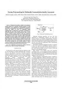
Fig. 1. Framework of RVWS. (a) Watermark embedding. (b) Watermark removal.
embedder are required to be easily transferred to any legal user while the original host image is forbidden in for recreating the receiver end. Obviously, these characteristics make the proposed algorithm different from any one in the literature. Ideally, the host image would be losslessly restored if the wa. However, distermark is completely removed, i.e., tortion-free recovery is difficult due to the requirement of large bit rate and strong strength in visible watermarking. Therefore, in this work, we only aim at the following objectives: 1) propose a user-key-controlled RVWS and implement it in discrete wavelet transform (DWT) domain and 2) introduce a preventive scheme against unauthorized operations such as removing the embedded watermark by using incorrect user keys. The letter is organized as follows. Section II discusses the strategy for constructing the RVWS. In Section III, we focus on the technique for implementing the RVWS in DWT domain. We also discuss our scheme to prevent unauthorized watermark removal in detail. In Section IV, we give some experiments to validate the proposed algorithm and analyze its performance. We draw the conclusion in Section V. II. STRATEGY FOR CONSTRUCTING RVWS The way of pixel-to-pixel embedding is commonly used in visible watermarking. One advantage is that we do not need to save spatial position information of watermark pixels in the resulting watermarked image. Before performing watermark addition, we establish a relationship of pixel-to-pixel correspondence between the host image and the watermark. This scheme has been commonly applied in both spatial and transform domain methods. The addition rule can be generally described as (1) or described in a manner of pixel-to-pixel addition as (2) is the embedding function; represents the set of where parameters of the embedder; , and are scalars corresponding to , , and , respectively. can be practically described with and , which are pixel-wise varying weighting factors for the host image and the watermark, respectively. The embedding of all elements in into the host image is obviously not suitable for constructing the RVWS. In this
letter, two factors will be taken into account when creating watermarked versions: the selection of watermark pixels to be embedded and the way of calculating embedding parameters. According to [13], revealing all the details of the watermark in the composite image is unnecessary and the watermark pattern can be displayed with the embedding of partial watermark pixels. This letter then suggests that different watermarked are created with different subsets of , i.e., . versions The subscript ( ) represents different individuals. is controlled by the user key. We put two constraints on . First, to ensure different watermarked the selection of versions to look like each other, must contain the basic . Second, subset consisting of visually significant pixels of to make a watermarked version numerically different from others, a user-key-dependent pre-watermarking template is used to put small amount of random pixels into to make . Apparently, . Let denote the subset which contains the watermark pixels not to be embedded. We then have . Reversibility requires watermark insertion and removal to be symmetric. Thus, needs to be resumable in the receiver end. However, the original host image is restricted in the process of removal. This implies that we can only use deliberately arranged host information to achieve adaptive embedding. As stated above, is to be embedded instead of , so that partial host pixels will be kept unchanged in the watermarked image. Let those unchanged host pixels constitute . Obviously, the pixels in are spatially correspondent to the watermark pixels in . We then suggest that can be used to provide the host features information for the calculation of embedding parameters. Thus, with and the correct user key, is known in the process of removal, so that the embedding parameters can be regained. We call the removal process with obtainable embedding parameters “informed detection”. In this letter, we define the “vaccine” program as a retrieval data packet containing three components: , the user key and the shared removing codes. The framework of the proposed RVWS is depicted in Fig. 1. The Watson’s just noticeable differences (JNDs) [14] are borrowed to choose visually significant pixels from . More explanation about Fig. 1 will be given in the next section. III. DWT-DOMAIN RVWS We propose a technique to implement the RVWS in DWT domain. For simplicity, the symbols defined in spatial domain will
IEEE TRANSACTIONS ON CIRCUITS AND SYSTEMS FOR VIDEO TECHNOLOGY, VOL. 16, NO. 1, JANUARY 2006
be directly used to denote their transform domain counterparts. Wavelet decomposition of an image can be expressed as
Elseif “1” in
131
and all of its 8 nearest neighbors correspond to
(3) where represents the low-frequency subband , the high-frequency subbands at scale . refers to the original corresponds to image. three high-frequency subbands in orientations , , and . ( ) denotes the decomposition scale. Let and correspond to the transform wavelet coefficients , images , and , respectively. Equation (2) is rewritten as follows:
where represents a coefficient in . represents . represents the mean of all unchanged coefficients in the mean of unchanged coefficients in the 8 nearest neighbors of the current position.
(4)
and represent a coefficient and the mean of all where , respectively. Thus, the embedding factors coefficients in can be determined with the value of the visual model as follows:
is not indicated unless confuNote that the coordinate sion arises. Before embedding, we perform wavelet decomposition on both the host image and the watermark. Due to different characteristics in low and high-frequency subbands, the RVWS is divided into two parts: low-frequency subband watermarking and high-frequency subbands watermarking. With the framework shown in Fig. 1, we describe these two parts in detail separately. A. Low-Frequency Subband Watermarking denote the set of low-frequency coefficients of . Let and represent the sets of low-frequency coefficients to be and not to be embedded, respectively. . In this letter, we use one user to explain the watermarking process. In order to determine , we introduce a user-key-controlled prewatermarking template . is a pseudo-random matrix with binary element that follows . We use uniform distribution. It has the same size of as a mask and put it on the low-frequency subband of the . All coefficients corresponding to “1” are watermark, chosen to constitute . Note that the Watson’s perceptual model is not used in low-frequency subband watermarking. is the user key. Since a user key The seed of generating uniquely corresponds to one specific user, we use to indicate either the user or the key. In order to design adaptive embedding, the calculation of and is based on a visual model which can describe the characteristics of the host low-frequency subband image, . We use the unchanged host coefficients, which spatially correspond to the watermark coefficients in , to construct a temporary subband image, . is introduced for calculating the value of the visual model. Intuitively, those unchanged host coefficients correspond to “0” in . Each coefficient in , , can be calculated in the following way. For the sake of simplicity, we ignore the superscript . If
corresponds to “0” in
Elseif corresponds to “1” in nearest neighbors correspond to “0”
Then the value of luminance masking model [13], be calculated as follows:
, can (5)
(6) (7) is the scaled and its value falls into a where narrow range [0.9,0.95] to avoid heavy embedding. Using and , we can embed all coefficients in into . In the process of watermark removal, when the , so that “vaccine” program is provided, we can determine the embedding parameters can be resumed and the “informed detection” can be accomplished in the low-frequency subband image. It is noted that the proposed embedding scheme only embeds a compressed version of low-frequency watermark subband image; besides, and derived from only approximately reflect the characteristics of . However, the experiments demonstrate that the watermarked images still have acceptable visual quality. B. High-Frequency Subbands Watermarking High-frequency subbands watermarking is similar to low-frequency subband watermarking but more complex. We use one subband to explain the situation. Let denote the set of all high-frequency watermark coefficients. Let and denote the sets to be and not to be embedded, respectively. Then . is composed of the union of and , where is the set of visually important watermark coefficients selected by the Watson’s JNDs and is the set determined using the user-key-controlled high-frequency prewatermarking template . is used to ensure . is constructed in a similar way as in low-frequency subband watermarking. Putting on the high-frequency subband, the coefficients corresponding to “1” are chosen to constitute . and . Practically, and in high-frequency subbands The calculation of watermarking is also based on a visual model. We consider the effects of both luminance masking and local spatial characteristics. For simplicity of discussion, we first give the formulas for calculating and as follows:
but some of its 8 (8) (9)
132
IEEE TRANSACTIONS ON CIRCUITS AND SYSTEMS FOR VIDEO TECHNOLOGY, VOL. 16, NO. 1, JANUARY 2006
(10) refers to the value of luminance masking. where and represent the decomposition scale and the current scale, describes local sparespectively. In (9) and (10) [4], tial characteristics, however, it no longer depends on the current coefficient but its neighbors for the reason of reversibility and anti-illegal-removal. The second item in (10) is mainly deis signed for preventing unauthorized watermark removal. a constant and ( ) is the number of unchanged host coefficients in the 8 nearest neighbors centered at the current coefficient. as the coefficient magnitude and is We define scaled . The use of (9) and (10) shows that our watermark embedding scheme abides by the principle of embedding more watermark energy in featureless regions and less in edges and denote a host coefficient rapidly changing regions. Let to be manipulated. can be calculated in the following way.
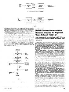
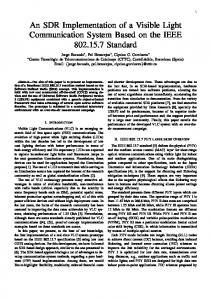
Fig. 2. Watermarked images (left and center) produced with two different user keys and their difference image (right). The gray value in the difference image is amplified for being displayed on screen.
TABLE I PSNR (DB) OF RECOVERED IMAGES. LR AND ILR DENOTE LEGALLY AND ILLEGALLY RECOVERED IMAGES, RESPECTIVELY
has some unchanged coefficients in its 8 nearest If neighbors
Elseif has no unchanged coefficients in its 8 nearest neighbors but some in its 24 nearest neighbors,
Else
where and represent the means of absolute values of unchanged host coefficients in the 8 and 24 nearest neighbors cen, respectively. denotes the mean of absolute tered at values of all unchanged host coefficients in the high-frequency is kept in the range [0.9,1] to ensubband. The value of sure moderate alteration to host coefficients. The second item in (10) reflects the influence on watermark embedding from the neighboring unchanged coefficients. Because is a user-key-controlled random number, the effect against unauthorized removal is significant. Due to the special , the number of marked coefficients is components of often larger than that of unchanged ones, so that is frequently smaller than 5. It can be estimated that the sum of and the first item in (10) is usually around 0.9, so we let . In the receiver end, given the “vaccine” program, we can obtain and . can be estimated, and then, and can be recalculated, so that the watermark removal can be accomplished. IV. EXPERIMENT AND DISCUSSION The proposed algorithm has been tested on several standard images. We use 9-7 wavelet and perform 4-level wavelet decomposition. Two watermarked images and their difference image
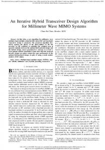
are shown in Fig. 2. Just as expected, the two watermarked versions look like each other. However, the difference image in the right discloses their numerical distinction. It can be easily found that the gray value difference exists almost everywhere in the image. The reason is that, in both low and high-frequency subbands, the calculation of weighting factors depends on the is embedded with changing user key mechanism, so that weighting factors as users are different. Usually, a legally recovered image has good visual quality. As shown in Table I, the peak signal-to-noise ratio (PSNR) is around 44 dB. However, an unauthorized user can not obtain with satisfactory quality. We compare the close-ups of legally and illegally restored images in Fig. 3. In the left close-up, mosslike unevenly darken areas spread across the entire image. They are especially visible in regions with middle gray intensity, such as face and shoulder. This visible distortion results from the fact that an unauthorized user, without the correct user key, can not accurately determine and thus blindly estimate and . Consequently, the watermark is overly subtracted in some coefficients and insufficiently subtracted in the others from the watermarked image. Although the PSNR is around 37 dB, the defect can be clearly seen on screen and certainly ruins the commercial value of the reconstructed image. The PSNR can not well reflect human perception in this case. We now examine the performance of the RVWS. From the PSNR values of normally recovered images (see Table I)
IEEE TRANSACTIONS ON CIRCUITS AND SYSTEMS FOR VIDEO TECHNOLOGY, VOL. 16, NO. 1, JANUARY 2006
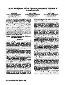
Fig. 3. Close-ups of two recovered images. (Left) Legally obtained image. (Right) Illegally obtained one. TABLE II OVERFLOW AND UNDERFLOW AT GRAY BOUNDARY. OF AND UF DENOTE THE NUMBER OF OVERFLOW AND UNDERFLOW POINTS, RESPECTIVELY
133
for RVWS based on the requirements of a promising application. The RVWS is completely dependent on a user key mechanism. Using the user key, we can not only implement the RVWS conveniently but also ensure security of the RVWS. The easy transfer of the “vaccine” program through the Internet enables the pixel-wise varying parameters of the embedder to be resumable in the receiver end and thus makes the detection informed. The image-adaptive embedding parameters, determined by both local host characteristics and the number of unchanged neighboring host coefficients, make unauthorized watermark removal almost impossible. The experimental results have demonstrated that the legally obtained image has very high visual quality. Future efforts will focus on two aspects: finding a more suitable transform to avoid rounding operation and setting a reasonable boundary condition to make overflow/underflow value invertible during addition. One way to avoid rounding error is to use integer wavelet transform. However, it needs to be further investigated. REFERENCES
we know that data loss occurs during watermark insertion and removal. Theoretically, data loss may result from several sources such as forward and backward DWT transforms, integer rounding operation, and overflow and underflow at gray boundary. In Table II, we find that, except images with large dark regions (e.g., Peppers) or large bright regions (e.g., Girl), overflow or underflow does not occur often in images with middle gray intensity. Table I further shows that the PSNR values of normally recovered Peppers and Girl are not too much different from others. This indicates that the effect of overflow and underflow is limited in the proposed RVWS. On the other side, the error from forward and backward wavelet transform is usually trivial even 9-7 wavelet is used. Therefore, we deduce that most errors come from integer rounding operation. Practically, when the wavelet coefficients are modified and the inverse DWT is applied, the watermarked image pixels must be rounded to integer values to form a digital image. V. CONCLUSION The issue of removable visible watermarking has been rarely studied in the literature. This letter proposes a new algorithm
[1] G. W. Braudaway, K. A. Margerlein, and F. C. Mintzer, “Protecting public-available images with a visible image watermark,” in Proc. SPIE Conf. Optical Security and Counterfeit Deterrence Techniques, vol. 2659, Feb. 1996, pp. 126–132. [2] J. Meng and S. F. Chang, “Embedding visible video watermarks in the compressed domain,” in Proc. IEEE Int. Conf. Image Processing, vol. 1, Oct. 1998, pp. 474–477. [3] S. P. Mohanty, K. R. Ramakrishnan, and M. S. Kankanhalli, “A DCT domain visible watermarking technique for images,” in Proc. IEEE Int. Conf. Multimedia and Expo., vol. 2, 2000, pp. 1029–1032. [4] Y. J. Hu and S. Kwong, “Wavelet domain adaptive visible watermarking,” IEE Electron. Lett., vol. 37, no. 9, pp. 1219–1220, Sep. 2001. [5] F. C. Mintzer, J. Lotspiech, and N. Morimoto. (1997, Dec.) Safeguarding digital library contents and users: Digital watermarking. D-Lib Magazine [Online]. Available: http://www.dlib.org/dlib/december97/ibm/12lotspiech.html [6] C. W. Honsinger, P. Jones, M. Rabbani, and J. C. Stoffel, “Lossless Recovery of an Original Image Containing Embedded Data,” U.S. Patent application, Docket No 77 102/E-D, 1999. [7] J. Fridrich, M. Goljan, and R. Du, “Invertible authentication,” in Proc. SPIE 2001, Security and Watermarking of Multimedia Contents III, vol. 4314, P. W. Wong and E. J. Delp, Eds., pp. 197–208. [8] C. De Vleeschouwer, J.-F. Delaigle, and B. Macq, “Circular interpretation of bijective transformations in lossless watermarking for media asset management,” IEEE Trans. Multimedia, vol. 5, no. 3, pp. 97–105, Mar. 2003. [9] Z. Ni, Y. Q. Shi, N. Ansari, and W. Su, “Reversible data hiding,” in Proc. IEEE Int. Symp. Circuits and Systems, vol. 2, Bangkok, Thailand, May 2003, pp. 912–915. [10] A. van Leest, M. van der Veen, and F. Bruekers, “Reversible image watermarking,” in Proc. IEEE Int. Conf. Image Processing, vol. 2, Sep. 2003, pp. 731–734. [11] A. M. Alattar, “Reversible watermark using the difference expansion of a generalized integer transform,” IEEE Trans. Image Process., vol. 13, no. 8, pp. 1147–1156, Aug. 2004. [12] J. Tian, “Wavelet-based reversible watermarking for authentication,” in Proc. SPIE Security and Watermarking of Multimedia Contents III, vol. 4675, P. W. Wong and E. J. Delp, Eds., pp. 679–690. [13] Y. J. Hu, J. Huang, S. Kwong, and Y. K. Chan, “Image fusion based visible watermarking using dual-tree complex wavelet transform,” in Proc. Int. Workshop Digital Watermarking, vol. LNCS 2939, 2003, pp. 86–100. [14] A. B. Watson, G. Y. Yang, J. A. Solomon, and J. Villasenor, “Visibility of wavelet quantization noise,” IEEE Trans. Image Process., vol. 6, no. 8, pp. 1164–1175, Aug. 1997.