of a stylus on the surface of the digitizing tablet. The initiation zone is stationary. A target stimulus, present only during trials, can be made to appear or disappear.
Behavior Research Methods, Instruments, & Computers 1985, 17 (4), 484-488
An Apple microcomputer-based laboratory system for the study of visual-motor behavior H. A. CUNNINGHAM Stanford University, Stanford, California An apparatus for studying motor control and visual-motor coordination is described. The system consists of an Apple II + with two expansions boards installed. One board provides advanced graphics capabilities; the other interfaces the Apple with a digitizing tablet and also provides a real-time clock. Target stimulus and visual feedback concerning self-produced movement (i.e., a cursor) are displayed on a standard video monitor, and movement data are sampled by the digitizing tablet. Software consists of about 3K bytes of assembled 6502 code and a 2K-byte Applesoft BASIC program. The system is inexpensive, versatile, and particularly well suited for developmental research. It has been used with human subjects as young as 3 years of age.
The ability of microcomputers such as the Apple IT to generate visual displays, control laboratory instrumentation, and measure reaction times has established their usefulness in the psychological laboratory (Cavanagh & Anstis, 1980; Rayfield, 1982; Rayfield & Carney, 1981). The difficulty of producing rapid and smooth movement of a visual stimulus using standard microcomputer graphics, however, has limited the application of microcomputers for research paradigms, such as the study of motor control and visual-motor coordination, that require rapid, smooth stimulus movement. Motor and visual-motor studies generally require that a subject make one or more movements of the hand and/or arm from a specific starting position to a target. Direction, amplitude, and accuracy constraints are placed upon the movement by varying the target's location and size. Dependent variables include aiming error, reaction time, and movement time (Fitts & Peterson, 1964; Keele, 1968; Wallace, Newell, & Wade, 1978). Implicit in a task of this nature is the availability to the subject of visual information concerning target location and of visual feedback concerning hand/arm movement. Complete computer implementation of these designs therefore requires the ability to generate a target, measure response parameters, and provide visual feedback to the subject concerning self-produced movement. In this paper, I describe how an inexpensive graphics interface can be combined with a digitizing tablet to make the Apple II capable of filling all of the above stated re-
The author wishes to thank Thom Carney for many valuable contributions to the design and execution of the project. Thanks also to Ed Kessler for hardware advice and helpful comments on the first draft, and to Misha Pavel for helpful comments during revision. This work was completed while the author was supported by a Stanford University Graduate Fellowship and with support from U.S. Air Force Grant No. AFOSR-840308. The author's mailing address is: Department of Psychology, Building 420, Stanford, CA 94305.
Copyright 1985 Psychonomic Society, Inc.
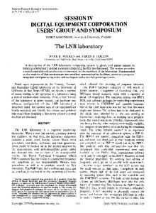
quirements for the study of motor control, with both the target stimulus and the visual feedback concerning selfproduced movement displayed on a standard video monitor or TV. The general procedure can be implemented on the Apple II, 11+, and lIe computers. In the present implementation, two stimuli are present at all times on a color monitor screen: a movable, subjectcontrolled cursor in the shape of a circle, and a trialinitiation zone defined by an open square. The cursor can be moved anywhere on the display screen by movements of a stylus on the surface of the digitizing tablet. The initiation zone is stationary. A target stimulus, present only during trials, can be made to appear or disappear at any specified time and location on the monitor screen. Centering the cursor over the initiation zone automatically initiates a trial. As presently implemented, a trial consists of a brief cuing tone that is followed, after a random foreperiod, by the onset of the target stimulus at some peripheral screen location. The subject's task is to encircle the target with the cursor. Target capture ends the trial. The target is extinguished immediately after capture, and computer-controlled performance feedback is given. Stylus position is sampled in real time and stored in Apple RAM, enabling playback and analysis of both spatial and temporal characteristics of movement trajectories. Figure I shows a display screen with three user-defined objects used in a developmental study. The system is implemented on an Apple II + computer with a graphics interface and a parallel interface board with a real-time clock installed in peripheral slots, a digitizing tablet with pen-like stylus, and a single disk drive. The software consists of 3K bytes of assembled 6502 code and a 2K-byte BASIC program, both of which are easily stored on tape or disk. These will be discussed in detail below. Storage of data constitutes the bulk of the memory requirement. Because data acquisition and storage depend on the individual experimenter's needs, however, they will be discussed only briefly.
484
VISUAL-MOTOR LABORATORY
TARGET
_
o
o
CURSOR
START ZONE
Figure 1. Display screen showing three user-defined objects employed in a motor task with young children. Objects are generated using the VDP sprite graphics interface. The open square in the center of the screen is the trial-initiation zone. The circle is the subject-controlled cursor. The abstract face is the aiming target.
HARDWARE The key to accurate visual feedback concerning selfproduced movement is the ability to move an object across the display screen smoothly and rapidly. The object also must respond virtually instantaneously to movement initiation. Noticeable lags and discontinuous or jerky movements are not acceptable. The Apple's intrinsic graphics capabilities are unsatisfactory in this respect. Graphics programming on the Apple can be done in either of two ways: (1) shape tables constructed and run in BASIC, and (2) bit-mapped graphics implemented in machine language. BASIC shape tables are essentially plotting instructions, and because execution in BASIC is very slow, it is impossible to obtain rapid, smooth, and instantaneous movement using this method. Bit-mapped graphics in machine language do provide satisfactory movement, but because screen memory locations do not map onto actual screen coordinates in any simple way, the required programming is cumbersome and time-consuming. With the addition of the graphics interface described in this paper, however, the Apple becomes capable of high-quality animation with relative ease of programming. The system uses a Texas Instruments (TI) TMS 9918A video display processor (VDP) with "sprite" graphics capabilities. Sprites are user-defined patterns which can be moved about the screen with relative ease. The TI display processor and 16K of memory are mounted on an expansion board designed specifically for the Apple and available from the Micromint (917 Midway, Woodmere, NY 11598). Cost is about $175 for the assembled board. The VDP provides screen resolution of 256 X 192 pixels. Up to 32 different sprite patterns, ranging in display size from one pixel to 32 x 32 pixels, can be stored at one time in the board's display memory (VRAM). Each sprite occupies a unique depth plane, which means that sprites can be made to pass behind and in front of one
485
another with ease. There is also a background plane on which static patterns may be displayed. Sprite patterns are accessed via an attribute table which specifies each sprite's VRAM address, color, and screen location. Changes in color (e.g., on vs. off) and location are effected simply by changing the appropriate entries in a sprite's attribute table; changes can be made very quickly. The graphics interface has its own video output which enables text to be displayed concurrently on another monitor, via the Apple's standard video output. Also, because screen memory resides in the board, Apple's screen memory areas are available for program and data storage. The board comes with complete technical documentation from Texas Instruments and some demo programs that can be viewed in the Apple's system monitor. In addition, an article by the owner of the Micromint describes the board and provides useful software routines (Ciarcia, 1982). For timing and for interfacing the digitizing tablet, this system employs a 6522 Versatile Interface Adapter (John Bell Engineering, P. O. Box 338, Redwood City, CA 94060). The cost is about $75 for the assembled board, which comes with complete technical documentation. In addition, a number of books on 6502 programming include sections on programming the 6522. Finally, Rayfield (1982) discusses in some detail the 6522's application to timing and I/O uses in the psychological laboratory . The timing application in this system is not substantially different from that described by Rayfield. The choice of a digitizing tablet must take into account the temporal and spatial resolution required for the kind of data to be collected. For rapid and smooth stimulus movement, temporal resolution is most important. The tablet used in this system is the BIT PAD ONE from Summagraphics Corp. (35 Brentwood Avenue, Fairfield, CT 06430).1 The cost of the tablet is approximately $960, which includes power supply ($135) and stylus ($95). With an institutional discount of 10%, this cost is reduced to $865. The tablet has an adjustable sampling rate of up to 200 points per second, excellent spatial resolution (.1 mm), and an absolute coordinate system (i.e., there is no loss of origin upon lifting the recording implement). A pen-like stylus or a flat "mouse" may be used as the input implement, depending on particular experimental needs. The BIT PAD's active surface is 11 in. square and stands about 1.5 in. above the surface on which it rests. The BIT PAD can communicate with another microprocessor using any of three standard interfaces: RS-232, IEEE-488, or 8-bit parallel. In the current system, a parallel interface was effected using the 6522 I/O ports and a standard 25-pin connector. The tablet comes with no software or demo programs, but the documentation is sufficiently detailed and clear to allow a person with some electronics experience to effect the interface. DISPLAY SOFI'WARE Display software consists of 6502 machine language routines that control the VDP interface. These routines
486
CUNNINGHAM
are loaded and called by an Applesoft BASIC executive program that also randomizes target presentation, counts trials, and controls performance feedback during the experimental session. The VDP interface is connected with Apple's CPU via an 8-bit bidirectional data bus, three control lines, and an optional (jumpered) interrupt line. The interface is accessed via peripheral slot memory locations; with the board installed in Slot 4, for example, control bytes are loaded and stored at hexadecimal location $COC1 and data bytes are loaded and stored at $COCO. The first step in programming the video display processor is to initialize its eight write-only registers. This is done by setting individual bits in each register via data byte transfers. Each data byte is followed by a control byte specifying type of transfer and the register to be addressed. Registers 0 and 1 control general graphics features such as graphics mode and sprite size. The contents of Registers 2-6 define VRAM base addresses for each of the tables used to define and access sprites and other user-defined patterns. VRAM locations are specified by 14-bit addresses. Register 7 is not used for graphics applications. Finally, the VDP has a read-only status register which is also not used in the present application. The next step is to load into VRAM the tables that define sprite patterns and sprite attributes. The pattern tables are bit-mapped sprite shapes, each defined on either an 8 x 8-bit grid or a 16 X 16-bit grid. These patterns are assembled into a sprite pattern table and sent to VRAM a byte at a time. See Figure 2 for an example of a l6-bit sprite pattern and the corresponding byte values sent to VRAM. The initial pattern size may be doubled by setting a bit in Register 1. The sprite attribute table is analogous to the index used to access shapes in a standard 00 00 03 t-+-t-tOC 10 10 20 20 20 20 10 10 OC 03 00 00
00 00
CO 30 08 08 04 04
04 04 08 08 30
CO 00 00
Figure 2. A 16-bit sprite pattern representing the cursor, with corresponding byte values. Bytes are sent to VRAM sequentially to form the sprite pattern table. Note-Adapted from TMS 9918A Video Display Processor by Texas Instruments, Inc., 1981.
Byte Number
01
VertIcal Position
02
Horillontal Position
OS
Sprite Number
04
x 0 0 0
05
Vertical Position
01
Horillontal Position
07
Sprite Number
08
x 0 0 0
;..... Sprite 00
Color
-
Sprite 01
Color
Figure 3. A sprite attribute table containing information for two sprites. Each sprite has x and y coordinate entries and a color entry. The zeros in bytes 4 and 8 are unused bits. The most significant bit of these bytes is used to control sprite behavior at the edges of the display screen. Note-Adapted from TMS 9918A Video Display Processor by Texas Instruments, Inc., 1981.
Apple BASIC shape table. Table entries specify sprite number (i.e., location in the sprite pattern table), sprite color, and the x and y coordinates of the sprite's screen location. See Figure 3 for an example of a sprite attribute table for two sprites. This table is loaded into VRAM in the same manner as the pattern table. Suggested VRAM table locations are provided in the TI documentation. The various sprite tables may be included in the general program or loaded separately. A separate loading program permits overwriting of that section of Apple RAM once loading is completed. After sprite patterns and attribute tables have been loaded into VRAM, rapidly changing a sprite's color or location merely requires an algorithm to compute the VRAM address of the relevant entries in the attribute table for the referenced sprite. The appropriate byte is then sent to that address. The algorithm can be invoked each time a sprite becomes active, or it can be done ahead of time and stored in a lookup table for faster execution. Target onset and offset are controlled by changing the sprite's color entry. A number of colors, including transparent (for target offset), are available. INPUT SOFTWARE Stylus position is transmitted by the digitizing tablet in x,y coordinate pairs which may be read at the Apple memory location corresponding to the 6522 input port. Each x,y location is sent in five bytes. The first is a control byte; the next four contain the x and y coordinates of stylus position. Data transfer consists of several steps: The tablet sends a control signal on the CA 1 line of the 6522 when a fresh data byte is available. This signal can be used to set a bit in the 6522's Interrupt Flag Register. A program loop tests this bit repeatedly until it is set; then the input port is read for the data byte. The byte is tested for the control value of 192 and, when this value is obtained, a counter is set and the next four bytes are read without
VISUAL-MOTOR LABORATORY testing their value. After each read of the input port, Apple sends a "data received" byte to the tablet via the appropriate 6522 output port. The value of each coordinate is given in two bytes, with each byte containing 2 control bits and 6 data bits. The result is a l2-bit x coordinate and a l2-bit y coordinate. This represents spatial resolution much greater than that needed in most experimental settings or available on standard video monitors; in this application, therefore, only the 8 most significant bits are used. The x and y coordinates are sent to the sprite attribute table to change cursor position and to Apple RAM as movement trajectory data. The entire process, from data read to completion ofVDP send, requires roughly .6 msec. With a fresh coordinate pair available every 5 msec, the Apple is able to perform other functions between data read operations. The tablet's sampling rate and the sprite capability of the graphics interface combine to produce rapid, smooth movement of the cursor stimulus. In fact, the only real limiting factor on cursor speed and responsiveness is not computing time, but rather the 60-Hz refresh rate of the video monitor (60 Hz is equivalent to once every 16.66 msec). This display rate yields smooth and virtually instantaneous cursor response. GENERAL SOFfWARE STRUCTURE AND MEMORY USAGE An Applesoft BASIC executive program runs the spriteloading routine and loads the other machine language routines into high memory. It also reads target display positions (x,y coordinates) from a text file, randomizes their presentation order, and sends the values to the machine language routine. After initializing constants, the BASIC program enters a trial initiation and feedback loop. Trial initiation is controlled by a keypress, a feature that is desirable in studies with children but can be modified easily for use with adult subjects. After the key is pressed, the BASIC program calls the main trial-execution routine, which controls all data acquisition, storage, display, and decision making during the trial. At the end of each trial, control returns to the BASIC program and feedback is given. With child subjects, feedback is given in the form ofa "song" generated by sending numbers from a DATA list to a tone-generating routine. With adult subjects, feedback can be a tone or a message printed to another monitor via the standard video output. The machine language routines consist of a main segment and a number of subroutines. The main segment initializes variables, evaluates flags, and calls subroutines. The following are examples of subroutines used during trial execution:
TREAD-Calls a utility routine to read the tablet and sends x,y coordinates to the VDP. SPON, SPOFF-Turn the target on and off, respectively.
487
PENPOS-Evaluates stylus position with respect to a criterion zone determined by STGOAL. STGOAL-Determines the upper, lower, right, and left bounds of a zone in which the stylus must be in order to satisfy a specified condition. STR-Keeps track of the number of points stored in a trial and, if appropriate, calls a utility routine to store the current x,y coordinate. CONVERTER-Converts 12-bit tablet data into 8-bit screen coordinates. JBBTIMER-Controls the VIA timers. Contains the interrupt service- routine used for timing. Stylus position is used as the basis for decisions during the trial, including whether to initiate the trial (250 samples obtained within the trial-initiation zone in order to initiate the trial), when to turn off the reaction time clock (on leaving the initiation zone), and when to end the trial (150 sampled points after reaching the target). Only those samples obtained between target onset and trial termination are stored as trajectory data. They are stored at a rate that is specified in the STR subroutine and is limited to multiples of the smallest inter-sample interval (5 msec). Although decisions about data acquisition and storage will depend on specific experimental needs, a brief description of the storage scheme developed for this application will be given. Storage of the x and y coordinates is done by a subroutine that uses zero-page indirect addressing to access Apple memory. The x and y coordinates are stored in separate memory ranges, each trial filling one memory page with 250 x coordinates and another memory page with 250 y coordinates. Base address is incremented to the next page for each new trial. At the end of a block of 16 trials, the trajectory data consist of an 8 I92-byte block ofx,y coordinates. As currently implemented on a 48K Apple II+, the system software leaves 24,576 bytes of memory free for data storage. This is equivalent to three 8192-byte blocks, or trajectory data for 48 trials. The data are saved to disk in binary format using Apple's BSAVE command. Binary format storage is used because it is faster and uses less disk space than text format. If data are to be shipped to a mainframe computer, then conversion to text format is necessary because communications systems do not generally support non-ASCII formats. The conversion need not be done at run time, however, and a separate BASIC program has been written to perform the conversion. Analysis programs for the present experiments are of two types. First, several BASIC programs have been developed for viewing the data. These include a plotting program that reads the trajectory data from memory and plots them using standard Apple graphics, and programs that read and display variables such as error flags and reaction times. Any of these can be used as a subroutine to the main BASIC program during an experimental session, with the restriction that the plotting routine uses Apple HIRES memory and will overwrite any data stored there.
488
CUNNINGHAM
Second, an analysis package has been implemented in the C language for complete spatial and temporal analysis of movement trajectories on a mainframe computer. These analyses are beyond the scope of the present report and will be described in detail at a later time.
data collection even with less than optimal stylus-tablet contact. Any child who can hold the stylus in a reasonably accurate manner can be tested, and the system has been used with children as young as 3 years of age. AVAILABILITY
CONCLUSION This system's generation of visual displays has several advantages over alternative methods. Compared to using an oscilloscope, for example, it is less expensive, requires less of the microcomputer's processing and memory capacity, and can be used to generate larger and more complex stimulus displays. Compared to methods in which the stimuli are LEDs or similar "real" objects, this system provides easy flexibility of stimulus size, shape, and color, as well as the capability for target movement. The use of a digitizing tablet permits the subject free movement in two dimensions. It also provides for easy reading and storing of stylus-position coordinates, with a high degree of spatial and temporal accuracy. This, in turn, facilitates analysis of movement trajectories on line or at a later time. The use of visual feedback given via a display screen (rather than direct viewing of the hand) has the clear advantage of permitting the experimental manipulation of the mapping relations between stimulus space and response space. The conversion of tablet coordinates into screen coordinates may be designed to create any desired mapping, making the system ideal for visual-motor adaptation studies. Finally, one of the greatest advantages of this system is its suitability for studying visual-motor behavior in children. A complex and colorful visual display increases the interest and motivation of young subjects. In addition, computers and video monitors are familiar to children, and the entire apparatus is easily taken to the subjectrather than requiring that the subject come to the laboratory, again increasing the likelihood of getting good experimental data from very young subjects. Additionally, the digitizing tablet used in this system is sensitive to stylus location from a vertical distance of up to % in. which allows
The routines described here (both source and object code) are available to interested readers. Please direct inquiries to the author at the Department of Psychology, Building 420, Stanford, CA 94305. REFERENCES CAVANAGH, P., & ANSTIS, S. M. (1980). Visual psychophysics on the Apple II: Getting started. Behavioral Research Methods & Instrumentation, 12, 614-626. CIARCIA, S. (1982, August). High-resolution sprite-oriented color graphics. Byte Magazine, pp. 57-80. FITTS, P. M., & PETERSON, J. R. (1964). Information capacity of discrete motor responses. Journal of Experimental Psychology, 67, 103-112. KEELE, S. W. (1968). Movement control in skilled performance. Psychological Bulletin, 70, 387-403. RAYFIELD, F. (1982). Experimental control and data acquisition with BASIC in the Apple computer. Behavioral Research Methods & Instrumentation, 14, 409-411. RAYFIELD, F., & CARNEY, J. (1981). Controlling experiments with BASIC on 6502-based microcomputers. Behavioral Research Methods & Instrumentation, 13, 735-740. TMS 9918A Video Display Processor. (1981). Houston: Texas Instruments, Inc. WALLACE, S.A., NEWELL, K. M., & WADE, M. G. (1978). Decision and response times as a function of movement difficulty in preschool children. Child Development, 49, 509-512. NOTE 1. The operation of the BIT PAD ONE is based on the propagation of strain waves along magnetostrictive wires under the tablet's surface. The stylus contains a receiver that detects the strain wave with a delay that is proportional to the distance of the stylus from the source of the wave. As an electromagnetic device, the tablet is susceptible to interference from nearby magnetic sources, and may also be a source of interference to electromagnetic reception in nearby devices. The author has not observed any problems of this kind in 3 years of laboratory use, but in certain environments (e.g., where pacemakers are used or where the magnetic search coil recording technique is employed) this digitizing technology might not be advisable.
(Manuscript received December 4, 1984; revision accepted for publication June 19, 1985.)