such as CRM (Customer Relationship Management), SCM. (Supply ... more details on our architecture for application integration, .... 39/HICSS06-slides.ppt ">.
> REPLACE THIS LINE WITH YOUR PAPER IDENTIFICATION NUMBER (DOUBLE-CLICK HERE TO EDIT)
REPLACE THIS LINE WITH YOUR PAPER IDENTIFICATION NUMBER (DOUBLE-CLICK HERE TO EDIT) < domain. It allows applications to agree on the terms, they use when communicating. However, an EAI model provides the language used to specify an explicit definition of an enterprise. It must have the expressiveness to capture the sets of applications, its activities that they perform and the resources required by these activities. One of the basic concepts, which enable us to capture the integration, is the structure, the behaviour and the domain of the application. The focus of this paper is on the application ontology building process based on Methontology [18]. A range of methods and techniques have been reported in the literature regarding ontology building methodologies [15]. Mike Uschold’s methodology [16], Michael Grüninger and Mark Fox’s methodology [17] and Methontology [18] are the most representative. Grüninger methodology is only limited to ontologies using first-order-logic languages. Uschold’s and Methontology have a common that they start from the identification of the ontology purpose and the need for domain knowledge acquisition. Uschold proposes a codification of knowledge in a formal language. In Methontology, a set of intermediate representations independent of the formal language to be used is expressed. Thus, Methontology enables experts and ontology designers who are unfamiliar with implementation environments to build ontologies from scratch. For the ontology evaluation, Ushold’s methodology includes this activity but does not state how to carry it out. Grüninger and Fox propose the identifying a set of competency questions. Evaluation in Methontology occurs throughout the ontology development. For our purpose, we have chosen the Methontology for the application ontology building. It enables the construction of ontologies at the knowledge level. It includes the identification of the ontology development process, a life cycle based on evolving prototypes and particular techniques to carry out each activity. III. INTEGRATION ARCHITECTURE In the system, we identify several types of legacy, client/server and Web applications, developed using different programming languages. They work on different operating system platforms and use various format for the exchange of data. By using application ontologies, we enhance communication between applications, for the benefit of integration. Hence, ontologies serve as stable basis for understanding the requirements for the user applications [10].
2
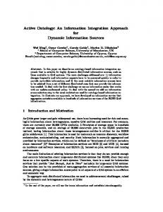
Fig.1. Integration system architecture
The integration system we propose aims at offering a support for integrating heterogeneous and distributed applications, accessing multiple ontologies (Fig.1). It provides a communication framework as a central service. It permits an appropriate exchange of information between applications ontologies and generates the global one. The introduced framework tries to enhance the ontology mapping, which enables the reuse of mapping information for managing heterogeneity. The integration process is based on the semantic bridges to indicate the semantic equivalence of ontology entities for assembling them. These applications are linked seamlessly to partners, vendors and suppliers through a common interface. Furthermore, we give an overview about the two-level approach for application integration, the applicative level and the collaborative one: - Applicative level consists of heterogeneous and distributed applications. Each application has its own local ontology. Our important direction is the development of a communication framework for ontology mapping. In our architecture, we aim to overcome the gap between local ontologies application, according to the semantic relations. A special component, named mapper, is invoked to perform its tasks for building the global ontology. The latter can be seen as enterprise ontology and permits the resolution of semantic conflicts in both concepts and attributes [10]. - Collaborative level takes place in the business process collaboration with partners. Each company has a mobile agent that is responsible for requesting and providing the services and the negotiation for selecting the best partner
> REPLACE THIS LINE WITH YOUR PAPER IDENTIFICATION NUMBER (DOUBLE-CLICK HERE TO EDIT) < basing itself on criteria (e.g., price limits, product configurations or delivery deadlines). It uses the collaboration scenario for achieving business process. The mobile agent permits to perform the integration tasks according to process ontology and using optimized itinerary. The latter improves the quality of the system and reduces the response time. The EbXML [20] extended scenario is based on the integration of agent paradigm to guarantee a saving of search time, to negotiate business parameters and to offer a great performance especially in the presence of the characteristic of mobility which solves problems related to the networks while decreasing consumption in resources networks [22]. IV. BUILDING APPLICATION ONTOLOGY In this section, we will build an application ontology which concerns EAI domain. For this purpose, the ontology consists of a classification of relevant characteristics of applications. We have some pertinent information about the application, such as application-behaviour, application-domain, application-structure …etc. These concepts are inspired from EAI domain [10], [12], Web services [4], [21] and middleware technologies [1]. Let us start the building of application ontology using Methontology [18], we have affected two modifications there, the first on the specification phase and the second on the conceptualization one. To determine the purpose of ontology, we follow the specification phase describes in [19]. In this work, an RDF document is created to describe ontology to be built through its objective, its developers, its creation date, its scope, etc.... In the conceptualization phase, we fused the step of construction of concepts classification trees with the step of construction of a relations binary diagram in order to show all ontology concepts in single diagram and to have a clear understandable view of all ontology concepts. A. Specification We suggest starting the development of ontology, the definition of its domain and its scope. Thus, we need to answer at some fundamental questions: • Which domain will cover ontology? • In which purpose ontology will be used? Ontology that we come to build concerns the domain of the enterprise application integration, we want to specify well the concepts relating to this domain and relations between them. These concepts must describe various types of applications, their models, their structures and the domain to which applications belong. We summarize this phase in RDF document presented in figure 2.
3
… Enterprise Application Integration September 30, 2006 Ontology modeling the behavioral and structural properties of an application and properties of domain in which the application belongs. This ontology will facilitate the integration of different applications of the enterprise … Fig.2 RDF-document specification for Application ontology
B. Conceptualization After the acquisition of the majority of knowledge in the first phase, we must organize and structure them by using semi-formal or intermediate representations which is easy to understand and independent of any implementation language. This phase contains several steps which are: Build the glossary of terms; Build the binary-relations and concepts classification diagram; Build the concepts Dictionary; Build the relations-tables; Build the attributes-tables; Build the logical-axioms table; Build the instances-table. 1) Build the glossary of terms: This glossary contains the definition of all terms relating to the domain (concepts, instances, attributes, relations) which will be represented in the application ontology, for example, in our case the terms Activity and E-Commerce are concepts but Set-of and Has-
> REPLACE THIS LINE WITH YOUR PAPER IDENTIFICATION NUMBER (DOUBLE-CLICK HERE TO EDIT) < precondition represent relations. The table 1 provides a detailed list of the various terms used in ontology.
Term name Application ApplicationBehavior ApplicationStructure ApplicationDomain Activity Atomic-activity Compositeactivity Input
TABLE I TABLE OF TERMS GLOSSARY Description An entity, a program or a set of activities having a certain behavior, a structure and a domain to which it belongs. Sub-ontology modeling the behavioral properties of an application. Characterized by a set of activities and a model of their execution. Sub-ontology modeling the structural properties of an application. It specifies the interface between the application and the middleware. Sub-ontology modeling the properties of the domain to which the application belongs. A function, a service, an entity or a work allowing to achieve such a spot. An activity which we cannot divide it into sub-activities. An activity which we can extract from other activities
An argument or a data which must be affected to an activity or program. Output Represents the result of the execution of an activity. Precondition Represents the conditions necessary to execute an activity. Effect Represents effects produced after the execution of an activity. An effect can prevent the execution of other activities. IDL-structure Affirms that the interfaces of an application are specified by IDL language, i.e. the application is connected to middleware CORBA. WSDLAffirms that the interfaces of an application are specified by Structure WSDL language, i.e. application represents a Web Service. FunctionalThis term allows to determine in which domain the description activity or the application belongs. Non-functionalThis term allows to determine in which domain the description parameter belongs. (…) (…) Provides Affirms that any application must have a certain behavior. Has-domain Affirms that any application must belong to a certain domain. Has-structure Affirms that any application must be connected to a middleware. Has-input Indicates that an activity must have input data. Has-output Indicates that an activity must present results. Description-type Indicates that the domain can have functional description and non functional description. Exp. Travel-service is a functional description Person is non functional description Maps-Method Affirms that the method name in interface of a middleware must correspond to an activity. Refers-to 1 Indicates that the functional description of term refers to an activity. Exp. Name_Instance1 is an instance of Hotel-reserv. Name_Activity1 is an instance of Activity. Name_instance1 refers to Name_activity1. Thus Name_activity1 is an activity of Hotel reservation. ( Hotel-reserv sub-class of Functional-description) Refers-to 2 Indicates that the non functional description of term refers to a parameter. Exp. Name_Instance1 is an instance of Hotel. Name_Parameter1 is an instance of Parameter. Name_instance1 refers to Name_Parameter1. Thus Name_Parameter is a parameter of Hotel. ( Hotel sub-class of non-functional-description) (…) (…) Name Indicates the application name of an activity… Type Indicates the type of the parameter. Code Represents the product code. (…) (…)
4
The hierarchy of concepts classification shows the organization of the ontology concepts in a hierarchical order which expresses the relations sub-class – super-class. We use the relation "Sub-Class-Of» between the classes to define their classification. C1 class is sub-class of C2 class if any instance of C1 class is an instance of C2 class. We follow a development process from top to bottom. We start with a definition of the general concepts of domain and then continue by the specialization of concepts. For example, we can start by creating classes for the general concepts: Application, Application-behavior, Application-structure, Application-domain, Application-Model, DomainDescription, Application-Model, Parameter, ComputedParameter, Application-Structure, Application-Structure, Output-Structure, Date, Interface-Structure, Product, MethodStructure, Transportation, Input-Structure, Level and Creator. 2) Build the binary-relations and concepts classification diagram: In this phase, we will build our diagram in two principal steps; initially, we determine the organization of concepts, then we will connect the concepts by relations so necessary. We represent the binary relations between classes by a diagram. In this diagram the classes are represented by rectangles and the relations by arrows (domain towards Codomain) labeled by the name of the relation. We enrich this diagram by adding dotted arrows (sub-class towards class) to illustrate the organization between concepts Figure 3 represents binary-relations and concepts classification diagram. We are always in the conceptualization phase, for each tree of concepts classification obtained in the previous step; we build the following intermediate representations: concepts Dictionary, relations-tables, attributes-tables, logical-axioms table, instances-tables. 3) Build the concepts Dictionary: In this step, we will accord a semi-formal description of concepts which were presented in the classes hierarchy, this process corresponds to the creation of concepts dictionary accorded to Methontology. In this dictionary, we define for each concept: instances, attributes, relations which the source is this concept, synonyms and acronyms of this concept; The table 2 represents a concepts dictionary for the domain « Application ». 4) Build the relations-tables: The binary relations are represented in the form of properties which attach a concept to another. For each relation whose source is in the tree of concepts classification, we define: its name, the name of the source concept, the name of the target concept, cardinality and the name of the inverse relation; For example, the table 3 represents a relations table for the domain « Application ».
> REPLACE THIS LINE WITH YOUR PAPER IDENTIFICATION NUMBER (DOUBLE-CLICK HERE TO EDIT)
REPLACE THIS LINE WITH YOUR PAPER IDENTIFICATION NUMBER (DOUBLE-CLICK HERE TO EDIT) < 5) Build the attributes-table: The attributes are properties which take its values in the predefined types (String, Integer, Boolean, Date…); for example the concept Parameter has attributes: Name, Text-description, and the type of the parameter. For each attribute appearing in the concepts dictionary, we specify: its name, type and interval of its possible values and its cardinality; for example, the table 4 represents an attributes table for the domain « Parameter ». 6) Build the logical-axioms table: In this step, we will define the ontology concepts by using the logical expressions which are always true. In the table below, we define for each axiom, its description in natural language, the name of the concept to which the axiom refers, attributes used in the axiom and the logical expression; we specify some axioms as it is represented in table 5. 7) Build the instances-table: In this section, we will present a description of some ontology instances, for that, we will specify the instances’ names and values of the attributes for each one of them; the table 6 illustrates some instances for each class. C. Formalization In this phase, we use the DL (Description Logic) [3] formalism to formalize the conceptual model that we obtained it at the conceptualization phase. DL forms a language family of knowledge representation; it allows to represent knowledge relating to a specific area using "descriptions" which can be concepts, relations and instances. The relation of subsumption allows to organize concepts and relations in hierarchy; classification and instantiation are the basic operations of the reasoning on description logic, or terminological reasoning. Classification permits to determine the position of a concept and a relation in their respective hierarchies. Description logic consists of two parts: terminological language TBOX in which we define concepts and relations; and an assertionnel language ABOX in which we introduce the instances. 1) TBOX construction: We define here concepts and relations relating to our domain, by using the constructors provided by description logic to give structured descriptions at concepts and relations; for example an activity must have a name and only one, a parameter in input, a parameter at output and produce an effect at the end of its execution. We can describe this sentence in description logic by: Activity= (∃ Name.String) (=1 Name.String) 0 Has-input.Input) ( 0 Has-output.Output) ( 0 Has-precondition.Precondition) ( 0 Has-effect.Effect). Moreover, we specify subsumption relations which exist between various concepts; for example to specify that the Activity class is subsumed by the Application
6
TABLE IV ATTRIBUTES TABLE FOR THE DOMAIN « PARAMETER » Attribute name Type values values Arrange Cardinality Name String (1,1) Text-description Type
String Thing
-
(1,n) (1,1)
TABLE V LOGICAL-AXIOMS TABLE Concept Axiom description Attributes Logical expression name used Application An application Has∀ X Application (X) must have a domain ∃ Y Applicationdomain domain(Y) Hasdomain (X,Y). Activity An activity must Has∀ X Activity(X) produce at the end of Output ∃ Y Has-output (Y) its execution a results Has-output(X,Y). Application- An application can Participates ∀ X Applicationinformation interact at the interior information(X) or at the exterior of the ∃ Y participates (Y) company. participates(X,Y). Parameter A parameter refers Refers-to ∀ X Parameter (X) ∃ Y to an activity Activity (Y) Refersto(X,Y). Composite- A composite activity ∀ X Composite-activity activity can be a sequence of (X) ⇒ (Sequenceactivities, Split activity activities or Choice (X) ∨ Splitactivities… activity(X) ∨ Choiceactivity (X) ∨ Repeat-until-activity(X) ) IDLAn application Has∀ X IDL-structure (X) structure must have an interface∃ Y Interface-structure interface with the structure (Y) / Has-interfacemiddleware structure (X,Y). Creator An application is Design∀ X Applicationconceived or by information (X) published by a ∃ Y Creator (Y) / company. Design-by (X,Y). DomainA domain is ∀ X Domaindescription described by description (X) ⇒ functional and (Functional-description non-functional (X) ∧ Non-functionalproperties. description (X) ) FunctionalA functional entity Refers-to ∀ X Functionaldescription must refer to an description (X) ∃ Y activity activity (Y) Refers-to (X,Y). NonA non-functional Refers-to ∀ X Non-functionalfunctionalentity must refer to description (X) ∃ Y description a parameter. parameter (Y) Refersto (X,Y). (…) (…) (…) (…)
class we write: Activity ⊆ Application Table 7 represents the definitions of some concepts However, we define relations by giving the couples of concepts source and concepts target of each one, and/or by specifying its inverse relation; for example the Has-parameter relation which connects an activity with its parameters is specified by: Has-parameter: (Activity, Parameter) Has-parameter: Refers-to- Table 8 represents the definitions of different relations of our ontology.
> REPLACE THIS LINE WITH YOUR PAPER IDENTIFICATION NUMBER (DOUBLE-CLICK HERE TO EDIT)
REPLACE THIS LINE WITH YOUR PAPER IDENTIFICATION NUMBER (DOUBLE-CLICK HERE TO EDIT)
REPLACE THIS LINE WITH YOUR PAPER IDENTIFICATION NUMBER (DOUBLE-CLICK HERE TO EDIT) < REFERENCES
DISCUSS In the literature, many approaches have proposed to integrate the applications enterprise. Wasserman [23] has classified the integration approaches in four classes which are principally: applications integration using data, treatments (function), presentations (interface) and processes. In our work, we developed an application ontology in order to integrate the enterprise applications. The construction of this ontology must be based on a model capturing structural and behavioral properties of an application. In addition, the properties on the domain to which the application belongs. The behavioral properties of an application were modeled by sub-ontology Application-behavior , which maintains the two integration approaches : by treatments and processes, the concepts of ontology Application-bahavior do not have any positive impact on integration without recourse to ontology Application-domain and Application-structure which also make it possible to define a concepts set in order to enrich or to increase the integration capacity and this one by providing a properties modeling of the application as well as properties on the application interfaces, i.e., the concepts set which facilitate to define how the application is connected to the middleware, for example: ‘IDL-structure’, ‘WSDLstructure’, etc.… In conclusion, the ontology is often seen as new solution providing exchange facilities of semantically enriched information, which can resolve the heterogeneity problem and ensure greater interoperability between the integrated applications. V. CONCLUSION The problem dealing with heterogeneity, even semantic has been deeply investigated in the field of ontology. We proposed an ontological approach for building application ontology. This approach enhances application integration at both applicative and collaborative levels. The important benefit of our work is that the communicator can reuse the mapping information for managing interaction between applications. Future work will focus on the development of global ontology by integrating the application ontologies for managing the enterprise information heterogeneity based on the semantic bridges concept [5]. A semantic bridge encapsulates all required information to translate instances of the source entity to instances of the target entity. So, the integrated applications can successfully and efficiently communicate and exchange information as well as services through the mapper component.
9
[1]
[2]
[3]
[4] [5]
[6]
[7]
[8] [9] [10]
[11]
[12] [13] [14]
[15] [16] [17]
[18]
[19]
[20] [21] [22]
[23]
D. Oberle, M. Sabou, D. Richards, “ An ontology for semantic middleware : extending DAML-S beyond Web services” International Conference on Ontologies, Databases and Applications of SEmantics (ODBASE), Catania, Sicily (Italy), Workshops, 3-7 November 2003. H. Panetto, M. Scannapieco, M. Zelm, “ INTEROP NoE : Interoperability research for networked enterprise application and software”, OTM Workshop, Lecture Notes in Computer Science, vol. 3292, SpringerVerlag, Heidelberg R. Meersman et al. edition, Berlin, pp. 866-882, 2004. F. Baader, P. Patel-Schneider, D. Calvanese, L. D. McGuinness, D. Nardi, editors. “The Description Logic Handbook”, Cambridge University Press, 2003. J. Chauvet, The book, Services Web avec SOAP, WSDL, UDDI, ebXML. Eyrolles edition, 2002. E. Gahleitner, W. Wob, “Enabling Distribution and Reuse of Ontology Mapping Information for Semantically Enriched Communication Services”, In: 15th International Workshop on Database and Expert Systems Applications. IEEE Computer Science, Zaragoza, Spain, 2004. H. Chalupsky, “OntoMorph: A Translation System for Symbolic Knowledge”, In the Seventh International Conference of Principles of Knowledge Representation and Reasoning, San Francisco, USA, 2000. D. Dou, D. Mcdermott, P Qi, “Ontology Translation by Ontology Merging and Automated Reasoning”, In EKAW, Workshop on Ontologies for Multi-Agent Systems (OMAS), Spain, 2002. V. Haarslev, R. Möller, “RACER System Description”, In IJCAR’01, 2001. Protégé OWL, version 3.1.1, 2005. http://protege.stanford.edu. R. Driouche, Z. Boufaida, F. Kordon, “An Ontology Based Architecture for Integrating Enterprise Applications”, Modelling, Simulation, Verification and Validation of Enterprise Information Systems’06 Workshop, Cyprus, Paphos, INSTICC Press, pp. 26-37, 2006. I. Horrocks, P. F. Patel-Schneider, F. V. Harmelen, “From SHIQ and RDF to OWL: The making of a web ontology language”, In Journal of Web Semantic, Vol. 1, N° 1, pp. 7-26, 2003. D. S. Linthicum. “Enterprise Application Integration”. Edition AddisonWesley, Boston et al. 2003. R. T. Gruber, “A Translation Approach to Portable Ontology Specification”, Knowledge Acquisition, Vol 5, N° 2, pp 199-220, 1993. S. Izza, L. Vincent, P. Burlat, “Unified Framework for Application Integration”. In 7th International Conference on Enterprise Information Systems’05, USA, 2005. M. F. Lopez, A.G. Perez, “Overview and Analysis of Methodologies for Building Ontologies”, In Knowledge Engineering Review, 17(2), 2002. M. Uschold, M. Grüninger, “Ontologies Principles Methods and Applications”, In Knowledge Engineering Review, 11(2), 1996. M. Grüninger, M. S. Fox, “Methodology for the Design and Evaluation of Ontologies”. In IJCAI’95, Workshop on Basic Ontological Issues in Knowledge Sharing, Montreal, 1995. M. Fernandez, A. Gomez-Perez, N. Juristo, “Methontology from Ontological Art Toward Ontological Engineering”, In AAAI’97, Spring Symposium Series on Ontological Engineering, USA, 1997. M. Hemam, Z. Boufaida “An Ontology Development Process for the Semantic Web”, EKAW’04, 14th International Conference on Knowledge Engineering and Knowledge Management Whittlebury Hall, Northamptonshire, UK, 5-8 October 2004 A. Kotok, D. R. R. Webber, “ebXML: The New Global Standard for Doing Business over the Internet”. New Riders, Indianapolis, 2002 K. Sycara, M. Stollberg, S. Galizia “Semantic Web Service Tutorial” Kauai 2006. R. Driouche, Z.Boufaida, F. Kordon, 2006 “Towards integrating collaborative business process based on process ontology and ebXML collaboration scenario” in 6 th International Workshop on Web Based Collaboration’06, IEEE Computer Society Krakow, Poland 4-6 September. Wasserman A I., “Tool Integration in Software Engineering Environments”. In software Engineering Environments; Workshop on Environments. Berlin 1990.