model is usually called the conceptual database model (CDM) and ...... Harmain, H., Gaizauskas, R.: CM-Builder: A Natural Language-Based CASE Tool.
DOI:10.2298/CSIS110318069B
An Approach to Automated Conceptual Database Design Based on the UML Activity Diagram Drazen Brdjanin and Slavko Maric University of Banja Luka, Faculty of Electrical Engineering Patre 5, 78000 Banja Luka, Bosnia and Herzegovina {bdrazen,ms}@etfbl.net
Abstract. This paper presents an approach to the automated design of the initial conceptual database model. The UML activity diagram, as a frequently used business process modeling notation, is used as the starting point for the automated generation of the UML class diagram representing the conceptual database model. Formal rules for automated generation cover the automatic extraction of business objects and business process participants, as well as the automatic generation of corresponding classes and their associations. Based on these rules we have implemented an automatic generator and evaluated it on a real business model. Keywords: Activity Diagram, Business Process Model, Class Diagram, Conceptual Database Model, UML, Topcased, ADBdesign.
1.
Introduction
The database design process mainly undergoes the following phases: requirements analysis, conceptual design, logical design and physical design. The main goal of conceptual database design is to provide an overall description of data on a high level of abstraction in the entire system. The corresponding model is usually called the conceptual database model (CDM) and represents a semantic data model. The related literature is more focused on conceptual design than on other design phases, considering it to be the most important design phase since the following phases are usually straightforward transformations of the model from the previous one. Because of that, the automatization of CDM design has been the subject of research for many years. Starting with Chen’s eleven heuristic rules [10] for the translation of information requirements specified in a natural language (English) into an E-R diagram, a lot of research has been done in the field of natural language processing (NLP) on extracting knowledge from requirements specifications and automating CDM design. At present, a natural language is the most frequently used language for requirements specifications and the majority of approaches to automated CDM design are NLP-based approaches. However, the effectiveness and limitations of NLP-based approaches are usually deeply related to the source language since they depend on the size and complexity of the grammar used and the scope of lexicon. Consequently, the utilization of linguistics-based
Drazen Brdjanin and Slavko Maric
approaches, which are presently mainly related to the English and German languages, is questionable for other languages with more complex morphology and some non-NLP-based alternatives are more desirable. Currently, there are several non-NLP-based alternatives to the automated CDM design, such as approaches taking a collection of forms [36, 3, 11, 12, 21] or diagrammatic requirements models [1] as the basis for automated design instead of requirements specifications expressed in a natural language. There are also several proposals taking business process models [15, 19, 32, 31, 7] as the starting basis, but with modest achievements in automated CDM generation. A more detailed overview of the related work is provided later in the paper. The fact that business modeling and database design often use different notations, which usually don’t conform to the same or common metamodel, poses a particular problem and challenge in the automated CDM design based on a business model. Business modeling is usually characterized by processoriented notations, such as IDEF0 [24], EPC [35], Petri nets [30], BPMN [39], etc. On the other hand, the E-R notation, introduced by Chen [9], or one of its modifications such as IE [22], is traditionally used for conceptual database modeling, while the development of UML has seen an increasing use of the UML class diagram as well [23]. Different, i.e. non-harmonized notations are one of the reasons for a fairly small number of papers in the field. One of the ways to overcome this problem is the use of UML for both business modeling and database design. In this paper we present an approach to the automated design of the initial CDM 1 using the unified UML-based notation. Another reason for the fairly small number of papers in the field, besides different and/or non-harmonized notations, is related to the semantic capacity of business models which has not been completely explored yet and should be exploited for the automated CDM design. Inspired by [15] and some subsequent proposals [4, 31, 37, 7, 6, 5], in this paper we explore the semantic capacity of the business process model represented by the UML activity diagram (AD), and define the formal rules for automated design of the initial CDM represented by the UML class diagram (CD). The proposed approach is based on: (i) automatic extraction of business entities (participants and objects) from the source AD, and (ii) automatic generation of corresponding classes and their associations (participant-object and object-object associations) in the target CD. This paper is structured as follows. After the introduction, the second section presents the AD as the source model, while the third section presents the CD as the target model. The fourth section presents an analysis of the semantic capacity of the AD, and provides the formal rules for automated generation of the initial CDM. The experimental results, including qualitative and quantitative evaluation of the implemented automated CDM generator, are given in the fifth section. The sixth section presents the related work. Finally, we conclude the paper and highlight the directions for further research. 1
Since the presented approach is currently focused on the automated generation of proper structure of the target data model that could be refined manually afterwards, we use the term initial CDM.
250
ComSIS Vol. 9, No. 1, January 2012.
An Approach to Automated Conceptual Database Design
2.
Detailed Activity Diagram
The AD is a widely accepted business process modeling notation [20] and there are a large number of papers dealing with the formalization of semantics and the suitability analysis of the AD for business modeling [34]. The very rich semantics of the AD allows modeling business processes at different levels of abstraction and detail, from the macroactivity diagram, used in developing the initial business model for the rough specification of a business process, to the detailed activity diagram, used for the detailed specification of a business process in later stages of business modeling. In this paper we consider a detailed activity diagram (DAD) which represents activities at least at complete level (related excerpt from the UML superstructure [28] is shown in Fig. 1), i.e. • each step in the realization of the given business process is represented by a corresponding action node (OpaqueAction) and will be shortly referred to as action in the rest of the paper; • each action is performed by a particular business process participant that plays some business role modeled by a corresponding activity partition (usually called swimlane). In the rest of the paper, a business process participant is shortly referred to as participant. It can be external (e.g. buyer, customer, etc.) or internal (e.g. business worker, working group, organization unit, etc.). Since the responsibility of a particular participant (i.e. corresponding business role) is modeled with one swimlane, we have as many swimlanes as there are different participants involved in the process represented by the given DAD; • each action may have a number of inputs and/or outputs represented by object nodes (CentralBufferNode) that can be in different states in the given business process. In the rest of the paper they are referred to as input objects and output objects, respectively; • objects and actions are connected with object flows (ObjectFlow). An object flow is a kind of activity edge which is directed from an input object toward the corresponding action (input object flow) or from an action toward the corresponding output object (output object flow); and • each object flow has a weight attribute, whose value is by default one. In UML semantics, the object flow weight represents the minimum number of tokens that must traverse the edge at the same time. We assume that the weight of an object flow represents the total number of objects required for an action if they are input objects, or the total number of objects created in an action if they are output objects. An unlimited weight (*) is used if the number of input/output objects is not a constant. The fact that an action is performed by some participant is represented in both corresponding DAD elements, i.e. the inPartition attribute of the corresponding action contains the identifier of the related swimlane, while the node attribute of the given swimlane contains the identifiers of all actions performed by the given participant.
ComSIS Vol. 9, No. 1, January 2012.
251
Drazen Brdjanin and Slavko Maric
The fact that an action has an input object is represented in all three corresponding DAD elements, i.e. the source and target attributes of the given input object flow contain the identifiers of the given object and action, respectively, while the outgoing attribute of the given object and the incoming attribute of the given action contain the identifier of the given input object flow. The fact that an action has an output object is similarly represented, i.e. the source and target attributes of the given output object flow contain the identifiers of the given action and object, respectively, while the outgoing attribute of the given action and the incoming attribute of the given object contain the identifier of the given output object flow. Based on the previous description of business process representation by the AD, the DAD can be formally defined as follows. Definition 1. (Detailed activity diagram) Let P, A, O and F be sets of participants, actions, objects and object flows in some business process, respectively. The detailed activity diagram, denoted by DAD(P, A, O, F), is a UML activity diagram with the following properties: (1) each action a ∈ A is performed by only one participant p ∈ P, i.e. ∀p ∈ P, ∀a ∈ A | a ∈ node(p) ⇒ inP artition(a) = {p}; (2) each input object flow if ∈ FI ⊆ F is an object flow directed from exactly one input object io ∈ OI ⊆ O toward exactly one action a ∈ A, i.e. ∀io ∈ OI , ∀a ∈ A, ∀if ∈ FI | if ∈ outgoing(io) ∧ if ∈ incoming(a) ⇒ source(if ) = io ∧ target(if ) = a; (3) each output object flow of ∈ FO ⊆ F is an object flow directed from exactly one action a ∈ A toward exactly one output object oo ∈ OO ⊆ O, i.e. ∀a ∈ A, ∀oo ∈ OO , ∀of ∈ FO | of ∈ outgoing(a) ∧ of ∈ incoming(oo) ⇒ source(of ) = a ∧ target(of ) = oo.
Fig. 1. UML metamodel [28] excerpt used for DAD representation
252
ComSIS Vol. 9, No. 1, January 2012.
An Approach to Automated Conceptual Database Design
Figure 2 depicts the sample DAD that will be used throughout this paper as the source business process model. Although it represents a simplified version of the DAD representing the typical business process of order acquisition followed by the delivery of ordered items, it is sufficiently illustrative to cover the most important concepts and basic rules for automated CDM design. Although the presented workflow is quite intuitive, we still provide a short description. The given business process starts with the customer’s request for a new order delivery. Based on that request, the commercial creates a corresponding new order header containing all relevant data and allows the customer to specify order details based on catalog items. After that, the commercial confirms the specified order details and makes the decision. If the order is acceptable, the order header will be marked as accepted. Otherwise, it will be canceled. After the order is accepted, the stockman collects stock items for all confirmed order details. All prepared items will be controlled and packed into a
Fig. 2. Sample DAD used in the paper as the source business process model
ComSIS Vol. 9, No. 1, January 2012.
253
Drazen Brdjanin and Slavko Maric
single delivery and delivered by the driver. Finally, the given business process ends with the reception of the delivery by the corresponding customer.
3.
Class Diagram as the Initial CDM
We use the CD to represent the CDM in an attempt to unify notations for both business modeling and CDM design. The UML metamodel excerpt from the UML infrastructure [27], required for the representation of the CDM, is shown in Fig. 3. Since the target CD is to represent the conceptual model of a relational database, each generated class will not contain operations, but only a set of owned attributes (data members). Since the presented approach is currently focused on automated generation of proper structure of the target model, each generated class will, if necessary, contain only one attribute named id, which represents a primary key. Additionally, all generated associations will be binary associations. Definition 2. (Conceptual database model) Let E and R be sets of classes and their associations, respectively. The conceptual database model, denoted by CDM(E, R), is a UML class diagram with the following properties: (1) each entity set is modeled by a corresponding class e ∈ E of the same name, whose each ownedAttribute (Property) corresponds to an attribute of the given entity set, and (2) each relationship is modeled by a corresponding binary association r ∈ R of the same name, whose two memberEnd attributes (Property) represent source and target association ends with the appropriate multiplicity corresponding to respective relationship cardinalities.
Fig. 3. UML metamodel [27] excerpt for CDM representation
254
ComSIS Vol. 9, No. 1, January 2012.
An Approach to Automated Conceptual Database Design
4.
Semantic capacity of DAD and rules for CDM design
This section presents an analysis of the semantic capacity of the DAD for automated generation of the CDM. Formal rules cover the extraction of business entities (participants and objects) from the DAD and automated generation of corresponding classes and their associations. At present, we distinguish two groups of associations. The first group are participant-object associations generated based on the actions performed by a particular participant on concrete object(s). The second group are object-object associations generated for the actions that have both input and output objects. 4.1.
Automated extraction of participants
Each business role in the given business process is represented by a corresponding swimlane in the DAD and there are as many swimlanes as there are different types of participants involved in the process. For example, in the sample DAD there are four different roles. The CUSTOMER is an external role, while the COMMERCIAL, STOCKMAN and DRIVER are internal roles. Each role is performed by a particular participant. With time, i.e. with multiple executions of the given business process, the same role may/will be performed by many different participants. External roles are a typical example. In the sample DAD, the CUSTOMER is an abstraction of all customers. For example, in one instance of the business process we have one particular customer, but in some other subsequent execution, the customer could be some other person or company. Similarly, the given business system may have many workers/units performing the same internal role. For example, the given business system may have many drivers. In each execution of the sample business process, one of them plays the DRIVER role and delivers items to the particular customer. In some other case, some other driver will deliver ordered items to the same or some other customer. To conclude, each role is an abstraction of a number of entities of the same type. That implies that each role should be represented by the corresponding entity type in the target CDM, i.e. each swimlane (participant) from the DAD is to be mapped into the corresponding class of the same name in the target CDM, which is formally expressed by the next rule. Rule 1. (Extraction of participants) Rule TP maps participant p ∈ P into class eP ∈ EP ⊆ E: � def TP : DAD(P, A, O, F) 7→ CDM(E, R) ⇐⇒ eP = TP p � def � TP p = eP name(eP ) = name(p) . Set EP of classes generated for all p ∈ P is as follows: n o EP = eP ∈ E eP = TP (p), p ∈ P . Application of the previous rule to the sample DAD is to result in the creation of four classes: CUSTOMER, COMMERCIAL, STOCKMAN and DRIVER.
ComSIS Vol. 9, No. 1, January 2012.
255
Drazen Brdjanin and Slavko Maric
4.2.
Automated extraction of objects
During the execution of a business process, participants perform actions and use different objects. We distinguish two categories of objects. The first category is generated objects, i.e. objects created in the given process. For example, the Request object is one of generated objects in the sample DAD, since it is created by a particular customer. In each subsequent execution of the given business process, one new request will be created by the same or some other customer. Other generated objects in the sample DAD are: OrderHeader, OrderDetail and Delivery. After they are created, generated objects may appear to be the input objects in other actions that may use them to create some other generated objects (e.g. an order header is created based on the customer’s request) or change their states (e.g. after the specification, each order detail is to be confirmed by the commercial). The second category is existing objects, i.e. objects that are not created in the given process but in some other process. They exist independently of the given business process. Such objects can be used for the creation of generated objects. For example, in the sample DAD, the CatalogItem is one type of existing objects which are used for the order details specification by the customer (each order detail is specified based on one catalog item). Existing objects may also be modified (may change their states) by the execution of some action, like the StockItem objects which are collected by the stockman and later packed into the delivery. Based on the previous considerations we can formally define existing and generated objects, since that is important for further DAD analysis. Definition 3. (Existing object) Existing object eo ∈ OX ⊆ O is an object which is not created in the given process but in some other process, i.e. ∀eo ∈ OX
⇒
6 ∃of ∈ FO | target(of ) = eo,
or alternatively eo ∈ OX = {o ∈ O | incoming(o) = ∅}. Definition 4. (Generated object) Generated object go ∈ OG ⊆ O is an object created in the given process, that is an object which is not ”existing”, i.e. go ∈ OG = {o ∈ O | o 6∈ OX }. In each execution of the given business process, participants deal with one or many (specified by the weight attribute of the corresponding object flow) instances of the specified objects. Even in case of manipulation with one single instance, in the course of time, i.e. with multiple executions of the given business process, many instances of particular object type will be used. To conclude, each object is an abstraction of many entities of the same type. That implies that each object should be represented by the corresponding entity type in the target CDM, i.e. each generated and each existing object from the DAD is to be mapped into a corresponding class of the same name in the target CDM, which is formally expressed by the next rule.
256
ComSIS Vol. 9, No. 1, January 2012.
An Approach to Automated Conceptual Database Design
Rule 2. (Extraction of objects) Rule TO maps object o ∈ O into class eO ∈ EO ⊆ E: � def TO : DAD(P, A, O, F) 7→ CDM(E, R) ⇐⇒ eO = TO o � def � TO o = eO name(eO ) = name(o) . Set EO of classes created for all generated and existing objects o ∈ OG ∪ OX in the given business process n is as follows: o EO = eO ∈ E eO = TO (o), o ∈ OG ∪ OX . Application of the previous rule to the sample DAD is to result in the creation of four classes for generated objects: Request, OrderHeader, OrderDetail and Delivery, as well as two classes for existing objects: CatalogItem and StockItem. 4.3.
Automated generation of participant-object associations
The first group of associations is participant-object associations which can be generated based on the actions that participants perform on objects. There are several typical patterns in the DAD that should be analyzed taking into account the distinction between generated and existing objects. Participant-generated object associations. Firstly, we will consider the associations of classes representing participants and generated objects. As defined earlier, a generated object is an object which is created in some action performed by a particular participant. In the given business process, some action may result in the creation of one or many generated objects of the same type (Fig. 4a), as specified by the weight attribute of the corresponding output object flow. In the course of time, i.e. with multiple executions of the given business process, the same or some other participant playing the same role will create many generated objects of the same type. Each generated object depends on exactly one participant that performs the given action and creates such object(s). This implies that such action is to be mapped from the DAD into the binary association of classes corresponding to the particular participant and generated object in the target CDM with the ”1:*” cardinality. For example, in the sample DAD, some customer requests a new delivery by issuing a new request. With time, the same customer may have many requests and all these requests will be related only to this customer. The first rule for automated generation of associations between classes corresponding to participants and generated objects defines the mapping of actions that create objects into corresponding associations. Consequently, these associations in the target CDM represent the fact that some objects are created by a particular participant.2 2
Each of these associations may have their own attributes (i.e. timestamp, etc.). Due to the ”1:*” cardinality, all these attributes will be attributes of the classes corresponding to the generated objects. Presently, we are focused on the proper structure of the target CDM and automated generation of attributes will be part of our future work.
ComSIS Vol. 9, No. 1, January 2012.
257
Drazen Brdjanin and Slavko Maric
Rule 3. (Creation of objects) Let action a ∈ A, performed by participant p ∈ P, create object o ∈ OG . Rule TPGO maps triplet hp, a, oi into association rPGO ∈ RPGO ⊆ R between classes eP and eG corresponding to the given participant and generated object, respectively: � def TPGO : DAD(P, A, O, F) 7→ CDM(E, R) ⇐⇒ rPGO = TPGO hp, a, oi � � def TPGO hp, a, oi = rPGO name(rPGO ) = name(a) ∧ memberEnd(rPGO ) = {source, target} | type(source) = eP ∧ multiplicity(source) = 1�∧ � type(target) = eG ∧ multiplicity(target) = ∗ . Let OGO (a) ⊆ O be the set of all generated objects of action a ∈ A. Then set RPGO (a) of all ”participant-generated object” associations, generated for all o ∈ OGO (a) for the given action a ∈ A, is as follows: n o RPGO (a) = rPGO ∈ R rPGO = TPGO (hp, a, oi), o ∈ OGO (a) . Total set RPGO of ”participant-generated object” associations representing facts of object creation for the entire DAD represents the union of all RPGO (a) sets [ RPGO = RPGO (a). a∈A
Application of the previous rule to the sample DAD will result in the creation of associations for the following triplets: , , and .
Fig. 4. Typical DAD patterns for generated objects and mapping into CDM
258
ComSIS Vol. 9, No. 1, January 2012.
An Approach to Automated Conceptual Database Design
Each generated object may appear to be the input object in some other action performed by the same participant (Fig. 4b). In the course of time, the given participant will perform such action many times and each time on a different input object generated in some previous action. This implies that such action is to be mapped from the DAD into the binary association of classes corresponding to the given participant and given input object in the target CDM with the ”1:*” cardinality. For example, in the sample DAD, the customer receives delivery. With time, the same customer may receive many deliveries and all these deliveries will be related only to this customer. More generally, each generated object may constitute the input object in several different actions performed by the same participant (Fig. 4c) or some other participants (Fig. 4d). For example, in the sample DAD, the order header is the input object in several subsequent actions: it is used for specification of order details (performed by the customer), it is the subject of cancelation or acceptance (performed by the commercial), and it is also used for preparing delivery (performed by the stockman). Based on the previous considerations, each of these actions with the same input generated object(s), is to be mapped into the binary association of classes corresponding to the particular participant and given input object(s) in the target CDM with the ”1:*” cardinality. The second rule for the automated generation of associations between classes corresponding to participants and generated objects defines the mapping of actions with generated objects as inputs into corresponding associations. Consequently, these associations in the target CDM represent the fact that some generated objects are used by a particular participant. Rule 4. (Usage of generated objects) Let action a ∈ A, performed by participant p ∈ P, have generated input object o ∈ OG . Rule TPGI maps triplet hp, a, oi into association rPGI ∈ RPGI ⊆ R between classes eP and eG corresponding to the given participant and input object, respectively: � def TPGI : DAD(P, A, O, F) 7→ CDM(E, R) ⇐⇒ rPGI = TPGI hp, a, oi � � def TPGI hp, a, oi = rPGI name(rPGI ) = name(a) ∧ memberEnd(rPGI ) = {source, target} | type(source) = eP ∧ multiplicity(source) = 1�∧ � type(target) = eG ∧ multiplicity(target) = ∗ . Let OGI (a) ⊆ O be the set of all generated input objects of action a ∈ A. Then set RPGI (a) of all ”participant-generated object” associations, generated for all o ∈ OGI (a) for the given action a ∈ A, is as follows: n o RPGI (a) = rPGI ∈ R rPGI = TPGI (hp, a, oi), o ∈ OGI (a) . Total set RPGI of ”participant-generated object” associations representing facts of generated objects usages for the entire DAD represents the union of all RPGI (a) sets [ RPGI = RPGI (a). a∈A
ComSIS Vol. 9, No. 1, January 2012.
259
Drazen Brdjanin and Slavko Maric
Finally, total set RPG of ”participant-generated object” associations for the entire DAD represents the union of the RPGO and RPGI sets RPG = RPGO ∪ RPGI . Some action having a generated object as an input object may change its state and such object can be used in other subsequent actions. For example, in the sample DAD, the commercial accepts an order header changing its state from new to accepted and that accepted order header is later used for preparing delivery. It is the same generated object, but in different states. Different states are represented by different attribute values and don’t affect the structure of the target CDM. That implies that the previous rule is relevant for all generated input objects regardless of their states3 . In this way, application of the previous rule to the sample DAD will result in the creation of associations for the following triplets: , , , , , , , and . Participant-existing object associations. As earlier defined, existing objects are objects which are not created in the given business process, but in some other process. We distinguish three typical usages of existing objects. Firstly, they may be used as input objects in actions without changing their state, i.e. actions which result in creating generated objects based on existing objects. Such existing object in the sample DAD is the CatalogItem used for the specification of order details. The statement that some participant uses some existing object for the creation of some generated object contains three main facts: (i) participant creates some new object, (ii) some new object will be generated based on some existing object, and (iii) participant uses some existing object. Each fact can be represented by a corresponding association. However, these three facts are not mutually independent and just two associations will suffice. The third association will be redundant (if we know that the given customer specified the order details based on catalog items, we indirectly know that (s)he used those catalog items). The first fact has been already covered by the rule for the automated generation of participant-generated object associations. The second fact is more significant than the third fact and will be represented by an object-object association4 . Consequently, there is no need for the automated generation of association of classes corresponding to the given participant and such existing object. 3
4
It is possible that the state of some generated object is not specified at all. For example, some object is naturally in state new after the creation, but that doesn’t need to be explicitly specified. Automated generation of object-object associations is the subject of the next section.
260
ComSIS Vol. 9, No. 1, January 2012.
An Approach to Automated Conceptual Database Design
The second typical usage of existing objects is the activation. It represents the fact that some existing object(s) constitute(s) the input in some action that changes its/their state. This implies that the given action has the input and output objects of the same name. The input object state (initial state of the given existing object(s) before the execution of the given action) is typically not depicted, while the output object state (state of the given object(s) after the action execution) is typically depicted, as illustrated in Fig. 5. Collecting stock items is an example of the existing object activation in the sample DAD. The stockman collects stock items and prepares them for packing and delivering. (S)he takes the items from the stock and changes their state into prepared. The term activation is used for two reasons: (i) such objects exist independently of the given business process in some idle state before the activation, and (ii) typically (but not necessarily), activation represents the initial usage of such existing objects in the business process, since the activated existing objects, after the activation, usually constitute the input objects in subsequent actions. Definition 5. (Existing object activation) Let OI (a) and OO (a) represent the sets of input and output objects of action a ∈ A, respectively. Action a, performed by participant p ∈ P, represents the activation α(p, a, eo) of existing object eo ∈ OI (a) if there is an output object oo ∈ OO (a) such that name(oo) = name(eo). By performing an activation, the given participant may activate one or many existing objects of the given type (specified by the weight attribute of the corresponding object flows). With time, the same participant may activate many existing objects. On the other hand, the same existing object(s) is/are activated by one participant in the given business process, but with time, it is possible that the same existing object will be activated many times by many different participants (some book in the library may be borrowed many times by many library members). Consequently, if we consider activation as a relationship between participants and existing objects, then its cardinality is ”*:*”. Since activation typically has its own attributes (e.g. state attributes, activation timestamp, etc.), we will not represent it as an association whose source and target end multiplicities equal ”*”, but as a separate class associated with both corresponding classes (participant and object) by two ”*:1” associations (Fig. 5).
Fig. 5. Existing object activation and corresponding CDM representation
ComSIS Vol. 9, No. 1, January 2012.
261
Drazen Brdjanin and Slavko Maric
Rule 5. (Activation of existing objects) Composite rule TPEA , consisting of (1) (2) (3) three rules TPEA , TPEA and TPEA , defines the mapping of activation α(p, a, eo) into a corresponding activation class and its associations. (1)
Rule TPEA maps activation α(p, a, eo) into activation class eA ∈ EA ⊆ E: def
(1)
(1)
TPEA : DAD(P, A, O, F) 7→ CDM(E, R) ⇐⇒ eA = TPEA α(p, a, eo) � def � (1) T α(p, a, eo) = eA name(eA ) = name(eo) + name(a) .
�
PEA
(2)
Rule TPEA maps activation α(p, a, eo) into association rPA ∈ RPA ⊆ R between classes eP and eA corresponding to the given participant and activation, respectively: � def (2) (2) TPEA : DAD(P, A, O, F) 7→ CDM(E, R) ⇐⇒ rPA = TPEA α(p, a, eo) � � def (2) TPEA α(p, a, eo) = rPA name(rPA ) = name(a) ∧ memberEnd(rPA ) = {source, target} | type(source) = eP ∧ multiplicity(source) = 1 �∧ � type(target) = eA ∧ multiplicity(target) = ∗ . (3)
Rule TPEA maps activation α(p, a, eo) into association rEA ∈REA ⊆R between classes eX and eA corresponding to the given existing object and activation, respectively: � def (3) (3) TPEA : DAD(P, A, O, F) 7→ CDM(E, R) ⇐⇒ rEA = TPEA hp, α(a, eo)i � � def (3) TPEA α(p, a, eo) = rEA name(rEA ) = name(a) ∧ memberEnd(rEA ) = {source, target} | type(source) = eX ∧ multiplicity(source) = 1 �∧ � type(target) = eA ∧ multiplicity(target) = ∗ . Let X be the set of all activations α(p, a, eo) in the given DAD(P, A, O, F). The EA , RPA and REA sets of classes and corresponding associations, created for all activations α(p, a, eo) ∈ X , are as follows: o n � (1) EA = eA ∈ E eA = TPEA α(p, a, eo) , α(p, a, eo) ∈ X , n o � (2) RPA = rPA ∈ R rPA = TPEA α(p, a, eo) , α(p, a, eo) ∈ X , n o � (3) REA = rEA ∈ R rEA = TPEA α(p, a, eo) , α(p, a, eo) ∈ X . There is only one activation () in the sample DAD. Application of the TPEA rule will result in the creation of an activation class (StockItem_Collecting) as well as two associations with classes corresponding to the given participant () and existing object (). The third typical usage of an existing object appears after activation when the activated existing object constitutes the input object in some subsequent actions performed by the same and/or some other participant(s), as illustrated
262
ComSIS Vol. 9, No. 1, January 2012.
An Approach to Automated Conceptual Database Design
Fig. 6. Usage of activated existing object and mapping into CDM
in Fig. 6. For example (sample DAD), after collecting, stock items are prepared (i.e. activated from the stock) for packing and constitute the input objects in the subsequent Pack&Control action. If an activated existing object constitute the input object in some subsequent action, then the given activated object is related to exactly one participant who performs that action. With time, the given participant will perform such action many times. Each time it may be performed on the same existing object, but also on some other activated existing object of the same type (e.g. the same library member may borrow the same book many times, as well as many different books). This implies that the cardinality of the relationship between the given participant and activated existing object is to be ”1:*”. To be able to define the formal rule that maps such action into the association of corresponding classes, the target class that corresponds to the given activated existing object is to be determined. The given participant performs the action with some concrete existing input object that was previously activated, i.e. (s)he is not related to any object of the given type, but to the particular activated object. This implies that the target class should be the class corresponding to the activation of the given object, but not the class representing all objects of the given type5 . 5
Associated activation class, representing the fact of activation of existing objects of the given type, is a weak entity type since each activation existentially depends on some concrete existing object. The primary key of this entity set will consist of the existing object identifier (i.e. primary key of the existing object) and some discriminator (e.g. activation timestamp). Each activation also depends on some concrete participant, but not existentially (if we suppose a slightly different business process metamodel that enables models containing only actions and objects, but without participants, activation will depend only on the existing object, i.e there is no activation without some existing object). Since the associated activation class contains complete identity information about the activated objects, as well as a set of other attributes representing the state of the activated objects, we can conclude that the associated activation class constitutes the relevant representation of the activated existing objects.
ComSIS Vol. 9, No. 1, January 2012.
263
Drazen Brdjanin and Slavko Maric
Consequently, an action representing the usage of activated existing object(s) in the DAD is to be mapped into the binary association of classes corresponding to the particular participant and activation of the given input existing object(s) in the target CDM with the ”1:*” cardinality (Fig. 6). Rule 6. (Usage of activated existing objects) Let action a ∈ A, performed by participant p ∈ P, have activated existing input object o ∈ OX . Rule TPEI maps triplet hp, a, oi into association rPEI ∈ RPEI ⊆ R between classes eP and eA corresponding to the given participant and activation of the existing input object, respectively: � def TPEI : DAD(P, A, O, F) 7→ CDM(E, R) ⇐⇒ rPEI = TPEI hp, a, oi � � def TPEI hp, a, oi = rPEI name(rPEI ) = name(a) ∧ memberEnd(rPEI ) = {source, target} | type(source) = eP ∧ multiplicity(source) = 1 �∧ � type(target) = eA ∧ multiplicity(target) = ∗ . Let OA (a) ⊆ O be the set of all activated existing input objects of action a ∈ A. Then set RPEI (a) of all ”participant-existing object” associations, generated for all o ∈ OA (a) for the given action a ∈ A, is as follows: n o RPEI (a) = rPEI ∈ R rPEI = TPEI (hp, a, oi), o ∈ OA (a) . Total set RPEI of ”participant-existing object” associations representing facts of activated existing objects usages, represents the union of all RPEI (a) sets [ RPEI = RPEI (a). a∈A
Total set RPE of ”participant-existing object” associations represents the union of RPEA and RPEI sets. Finally, total set RPO of ”participant-object” associations for the entire DAD represents the union of all ”participant-generated object” and ”participant-existing object” associations, i.e. RPO = RPG ∪ RPE = RPGO ∪ RPGI ∪ RPEA ∪ RPEI . The previous rule is relevant for the triplet in the sample DAD. Its application will result in the creation of one association in the target CDM between classes STOCKMAN and StockItem_ Collecting that correspond to the given participant and existing object activation. Some action having an activated existing object as the input object may change its state and such object can be used in other subsequent actions. This case is not depicted in the sample DAD, but it is possible. By dividing the Pack&Control action into two separate subsequent actions, Check and Pack, each prepared stock item will be firstly checked before packing, i.e. action Check will change the state of each activated object from prepared to checked. It is the same activated existing object, but in different states. Since different states are represented by different attribute values, this case doesn’t affect the structure of the target CDM and there is no need for additional associations (analogy with generated objects usage).
264
ComSIS Vol. 9, No. 1, January 2012.
An Approach to Automated Conceptual Database Design
4.4.
Automated generation of object-object associations
The second group of associations is object-object associations, i.e. associations between classes representing business objects. They can be automatically generated based on actions that have both input and output objects by direct mapping of these actions into the respective associations. Actions with input and output objects may be classified based on the number of different types of input and output objects. There are several possible situations (Fig. 7) and they are as follows: (i) single input - single output (SISO) actions, (ii) multi input - single output (MISO) actions, (iii) single input - multi output (SIMO) actions, and (iv) multi input - multi output (MIMO) actions. In the sample DAD, an example of SISO actions is the HeaderCreation action, since it has input object(s) of exactly one type (Request) and output object(s) of exactly one type (OrderHeader). In the given example, each execution of this action takes exactly one customer’s request and creates exactly one order header. However, generally it is possible that some SISO action takes more than one input object of the same type and/or has more than one output object of the same type, which is denoted by the weight attribute. Although the Confirmation, Cancelation, Acceptance and Delivering actions have the input and output objects of exactly one type, they don’t belong to the SISO category since each of these actions has input and output objects of the same type (they only change the objects’ states). Such actions have already been covered by the previous rules (Rule 4 and Rule 6). The Specification action represents the first example of MISO actions in the sample DAD. This action, which has input objects of two different types (OrderHeader and CatalogItem), results in the creation of one or many objects of the third type (OrderDetail). The second MISO action is the Pack&Control action, also having input objects of two different types (OrderHeader and StockItem) and resulting in the creation of one object of the third type (Delivery). Although the Collecting action has input objects of two different types (OrderDetail and StockItem), it doesn’t belong to the MISO category. It represents the activation of the StockItem objects (already covered by Rule 5) and actually belongs to the SISO category (one or many stock items are prepared for the each confirmed order detail).
Fig. 7. Classification of actions: (a) SISO, (b) MISO, (c) SIMO, and (d) MIMO
ComSIS Vol. 9, No. 1, January 2012.
265
Drazen Brdjanin and Slavko Maric
There are no SIMO and MIMO examples in the sample DAD, but they are possible. For example, in the production unit of the given business system, separation of some mixture into its components constitutes a SIMO action. Such action has object(s) of exactly one type (mixture) and as many different types of output objects as there are different types of components in the mixture. If we add machine(s) required for the separation (machine, as an existing object, will constitute an additional input object), or some previously prepared containers for packing separated components (prepared containers, be they generated and/or activated existing objects, will also constitute additional input objects), then such SIMO action becomes a MIMO action. Generally, input objects may be: (i) generated (ioG ∈ OG ), (ii) activated exista ing (ioA ∈ OX ), i.e. existing objects that have been already activated by some previous action in the given business process, and (iii) non-activated existing n ), i.e. existing objects that have not been activated in the given busi(ioX ∈ OX ness process. On the other hand, output objects may be: (i) generated (ooG ), and (ii) activated existing (ooA ). Classes eG ∈ EG and eX ∈ EX in the target CDM, corresponding to generated and non-activated existing objects, respectively, are created by Rule 2 (extraction of objects), while classes eA ∈ EA , corresponding to activated existing objects, are created by Rule 5 (activation of existing objects). These classes will constitute the source and target classes in the mapping of SISO, MISO, SIMO and MIMO actions into the corresponding object-object associations. SISO actions. Firstly we will consider SISO actions. SISO cases and the corresponding transformation rules are illustrated in Fig. 8.
Fig. 8. Illustration of transformation rules for SISO actions
266
ComSIS Vol. 9, No. 1, January 2012.
An Approach to Automated Conceptual Database Design
Each output object (be it generated or activated existing) depends on as many input objects as is the weight of the given input object flow. Thus, if the weight of the corresponding input object flow equals "1", then the given output object depends on exactly one input object and the multiplicity of the respective source association end (corresponding to the input object) is exactly "1". If the input weight equals "*", then the given output object depends on many input objects and the multiplicity of the respective source association end is "*". If the input weight is a literal n (n >1), then the given output object depends on exactly n input objects (like personal data containing data about two cities, where the first city represents the place of birth, while the second city represents the place of residence). In that case we have exactly n associations, where each association has the source end multiplicity equal to "1". If the input object(s) is/are non-activated existing object(s), i.e. ioX , then the target end multiplicity (which corresponds to the output object) of each association always equals "*" and doesn’t depend on the weight of the output object flow, because even in cases when the output weight is exactly "1", with time, the same existing input object may be used in the creation/activation of many output objects. If the input object(s) is/are generated or activated existing object(s), i.e. ioG or ioA , then the target end multiplicity depends only on the weight of the output object flow. If the output weight is exactly "1", then exactly one output object depends on ioG or ioA and the target end multiplicity should be exactly "1". Otherwise, the target end multiplicity should be "*" because more than one output object depend on given input object(s). Rule 7. (Object-object associations for SISO actions) Let a ∈ A be a SISO n a and output object(s) oo ∈ OO , ∪ OX action with input object(s) io ∈ OG ∪ OX where if ∈ FI and of ∈ FO represent corresponding input and output object siso flows whose weights are denoted by wif and wof , respectively. Rule TOO maps siso SISO tuple hio, if, a, of, ooi into set ROO (a) containing exactly n ∈ N associations between classes eIO and eOO : � def siso siso TOO : DAD(P, A, R) ⇐⇒ Rsiso of, ooi OO (a) = TOO hio, if, a, o n O, F) 7→ CM(E, (j) � (j) ∗ Rsiso OO (a) = rOO ∈ R rOO = TOO hio, if, a, of, ooi , j = 1, ..., n � � def ∗ TOO hio, if, a, of, ooi = rOO name(rOO ) = name(a) ∧ memberEnd(rOO ) = {source, target} | type(source) = eIO ∧ multiplicity(source) = ms � ∧ � type(target) = eOO ∧ multiplicity(target) = mt , where the corresponding source and target classes eIO and eOO are given with: � eG , io ∈ OG eG , oo ∈ OG n eIO = eX , io ∈ OX eOO = a , eA , oo ∈ OX a eA , io ∈ OX while the corresponding source and target association end multiplicities and the total number of associations are as follows:
ComSIS Vol. 9, No. 1, January 2012.
267
Drazen Brdjanin and Slavko Maric
� ms =
∗, wif = ∗ mt = 1, otherwise
�
n ∗, wof 6= 1 ∨ io ∈ OX n= 1, otherwise
�
1, wif ∈ {1, ∗} . wif , otherwise
Application of the previous rule to the first sample SISO action (HeaderCreation) will result in the creation of a binary association between the classes corresponding to the input and output objects (Request and OrderHeader) with the ”1:1” cardinality since both input and output objects are generated and the weight of corresponding object flows equals ”1”. Application to the de facto SISO action (Collecting) will result in the creation of a binary association between the class corresponding to the input object (OrderDetail) and class corresponding to the activation of the output object (StockItem_Collecting) with the ”1:*” cardinality, since the input is a generated object and the output is an activated existing object, while the weights of the corresponding object flows are ”1” and ”*”, respectively. MISO actions. Each MISO action has input objects of more than one type and it creates output objects of exactly one type. Since all input objects are required for the start of an action, we assume that the output object(s) depend(s) on all these input objects, i.e. output object(s) is/are directly related to each of the input objects. For example, in the sample DAD (Pack&Control), each delivery (represented by output object type Delivery) is related to one order (represented by the first input object type OrderHeader) and contains many items (represented by the second input object type StockItem). Similarly, for the second sample MISO action (Specification), all order details (represented by output object type OrderDetail) belong to a particular order (represented by the first input object type OrderHeader) and each of them is specified based on a concrete catalog item (represented by the second input siso should be indeobject type CatalogItem). This implies that SISO rule TOO pendently applied to each input object(s) - output object(s) pair of MISO action, as depicted in Fig. 9 (a).
Fig. 9. Application of SISO transformation rule for MISO (a) and SIMO (b) actions
268
ComSIS Vol. 9, No. 1, January 2012.
An Approach to Automated Conceptual Database Design
Rule 8. (Object-object associations for MISO actions) Let a ∈ A be a MISO action with m ∈ N different types of input objects io1 , . . . , iom ∈ OI and output object(s) oo ∈ OO , where if1 , . . . , ifm ∈ FI and of ∈ FO constitute the corresponding input and output object flows, respectively. Let M(a) = {hiok , ifk , a, of, ooi, miso 1 ≤ k ≤ m} be the set of all SISO tuples for the given action a ∈ A. Rule TOO miso maps the M(a) set into the ROO (a) set of corresponding associations for the given action: � def miso miso M(a) TOO : DAD(P, A, O, F) 7→ CM(E, R) ⇐⇒ Rmiso OO (a) = TOO def
Rmiso OO (a) =
[
(k)
ROO (a),
� (k) siso ROO (a) = TOO hiok , ifk , a, of, ooi .
1≤k≤m miso The TOO rule is a general rule relevant to all single output actions, since a SISO action is just a special case of MISO actions (m = 1). Application of the previous rule to the first MISO action (Pack&Control) in the sample DAD will result in the creation of two binary associations: (i) ”1:1” association between classes corresponding to the input (OrderHeader) and output object (Delivery), and (ii) ”*:1” association between the class corresponding to the activation of input objects (StockItem_Collecting) and the class corresponding to the output object (Delivery). Similarly, application to the second sample SIMO action (Specification) will result in the creation of the following two binary associations: (i) ”1:*” association between classes corresponding to the input (OrderHeader) and output object (OrderDetail), and (ii) ”1:*” association between classes corresponding to the input (CatalogItem) and output object (OrderDetail).
SIMO actions. A SIMO action has input objects of exactly one type and output objects of more than one different type. Since the given action is to result in the creation/activation of all output objects, we assume that each output object siso is directly related to the given input object(s). This implies that SISO rule TOO should also be independently applied to each input object(s) - output object(s) pair of a SIMO action, as illustrated in Fig. 9 (b). Rule 9. (Object-object associations for SIMO actions) Let a ∈ A be a SIMO action with input object(s) io ∈ OI as well as n ∈ N different types of output objects oo1 , . . . , oon ∈ OO , where if ∈ FI and of1 , . . . , ofn ∈ FO represent the corresponding input and output object flows, respectively. Let M(a) = {hio, if, a, ofk , ook i, 1 ≤ k ≤ n} be the set of all SISO tuples for the simo given action a ∈ A. Rule TOO maps the M(a) set into the Rsimo OO (a) set of corresponding associations for the given action: � def simo simo TOO : DAD(P, A, O, F) 7→ CM(E, R) ⇐⇒ Rsimo M(a) OO (a) = TOO def
Rsimo OO (a) =
[
(k)
ROO (a),
� (k) siso ROO (a) = TOO hio, if, a, ofk , ook i .
1≤k≤n
ComSIS Vol. 9, No. 1, January 2012.
269
Drazen Brdjanin and Slavko Maric
MIMO actions. A MIMO action has m ∈ N different types of input and n ∈ N different types of output objects. Following the same analogy as for MISO actions, we can conclude that each output object of MIMO action depends on each input object. This implies that each MIMO action can be considered as a set of n concurrent MISO actions. For example, a supposed MIMO action (separation of components) can be treated as a set of several MISO actions such that each MISO action represent extraction of one component from the input mixture. In this way each separated component depends on the input mixture as well as the separation machine. Similarly, following the same analogy as for SIMO actions, each MIMO action can also be considered as a set of m concurrent SIMO actions. Since each MISO action can be considered as a set of m SISO actions, each MIMO action can be considered as a set of m ∗ n SISO actions. Consequently, siso rule should be applied to all these SISO tuples of a MIMO action. the TOO Rule 10. (Object-object associations for MIMO actions) Let a ∈ A be a MIMO action with m ∈ N different types of input objects io1 , ..., iom ∈ OI and n ∈ N different types of output objects oo1 , ..., oon ∈ OO , where if1 , ..., ifm ∈ FI and of1 , ..., ofn ∈ FO constitute the corresponding input and output object flows, respectively. Let M(a) = {hioj , ifj , a, ofk , ook i, 1 ≤ j ≤ m, 1 ≤ k ≤ n} be the set mimo of all SISO tuples for the given action a ∈ A. Rule TOO maps the M(a) set mimo into the ROO (a) set of corresponding associations for the given action: � def mimo mimo TOO : DAD(P, A, O, F) 7→ CM(E, R) ⇐⇒ Rmimo M(a) OO (a) = TOO def
Rmimo OO (a) =
[
(j,k)
ROO (a),
� (j,k) siso ROO (a) = TOO hioj , ifj , a, ofk , ook i .
1≤j≤m 1≤k≤n
MISO and SIMO actions represent special cases of MIMO actions (for MISO actions n = 1, for SIMO actions m = 1). Consequently, the aforementioned Rule 10 (MIMO actions) and basic Rule 7 (SISO actions) constitute general rules for mapping actions with both input and output objects into the corresponding object-object associations. 4.5.
Order of application of the rules
The process of the automated CDM design, i.e the proper order of application of the rules, is determined by the mutual dependence of the rules. Generally, the rules that create classes are to be applied before the rules for automated generation of associations since the associations cannot be generated if there are no previously generated classes. However, some rules are mutually independent and can be applied in any order. More concretely, the rules that create classes for the extracted participants (Rule 1) and objects (Rule 2) are to be applied before the rules for automated generation of associations (Rules 3-10). These two rules for automated generation of classes can be applied in any order due to their mutual independence.
270
ComSIS Vol. 9, No. 1, January 2012.
An Approach to Automated Conceptual Database Design
The rules for automated generation of participant-generated object (Rules 3-4) and participant-existing object (Rules 5-6) associations are also mutually independent and can be applied in any order, too. It is only important that the rule for mapping activation of existing objects (Rule 5) be applied before the rule for the usage of activated existing objects (Rule 6). The rules for automated generation of participant-object associations (particularly Rule 5) are to be applied before the rules for automated generation of object-object associations (Rules 7-10) since the rule for mapping activation of existing objects results in the creation of an activation class that may be used in automated generation of object-object associations. Finally, the automated generation of all object-object associations can be performed by applying the MIMO rule (Rule 10) that uses the basic SISO rule (Rule 7)6 .
5.
Experimental Results
Automated generator. The target automated generator of the initial CDM is implemented as a Topcased7 [38] plugin named ADBdesign whose prototype has already been presented in [7]. This improved release implements all previously formally specified rules. The functionality of the Topcased platform and the implemented generator is based on the standard UML2 Eclipse plugin as the EMF8 - based [8] implementation of the UML 2.1 specification for the Eclipse platform, which enables visual UML modeling, as well as the program generation of UML diagrams, and ensures a satisfactory visualization of automatically generated diagrams. Each UML diagram in the Topcased model is represented by two files of the same name, but different extensions. The .uml file contains the XMI9 representation of the diagram, while the .umldi file describes its visualization. The implementation is based on the combination of the DOM XML parser for the source diagram analysis and the UML2 factory [17] for the target diagram generation. The generator processes the source .uml file containing the DAD description and generates the target .uml file containing the CDM representation. The visualization of the automatically generated CDM, i.e. generation of the corresponding .umldi file, is performed by using the integrated Topcased functionality for the automatic visualization. 6
7 8 9
As previously mentioned, MISO and SIMO actions are special cases of MIMO actions and, consequently, all object-object associations can be generated by applying the MIMO rule. Toolkit in OPen-source for Critical Application & SystEms Development Eclipse Modeling Framework XMI (XML Metadata Interchange) [25] is the OMG standard for platform independent metadata interchange enabling the serialization of MOF (Meta-Object Facility)-based models and metamodels into XML and vice versa, the visualization of MOF-based models and metamodels from XML.
ComSIS Vol. 9, No. 1, January 2012.
271
Drazen Brdjanin and Slavko Maric
Automatically generated sample CDM. The implemented generator has been applied to the sample DAD (Fig. 2). The visualization result of the automatically created CDM is depicted in Fig. 10.
Fig. 10. Automatically generated CDM based on sample DAD
The implemented generator has created all 11 classes, as was expected during the analysis of the sample DAD, and they are as follows: (i) four classes corresponding to the participants, (ii) four classes corresponding to the generated objects, (iii) two classes corresponding to the existing objects, and (iv) one class corresponding to the activation of the existing objects. An overview of all automatically generated classes is given in Table 1. The implemented generator has created all 22 associations, as was expected based on the analysis of the sample DAD. An overview of all automatically generated associations is given in Table 2. Table 1. Overview of automatically generated classes based on sample DAD Rule
Automatically generated classes
#1: TP (participants)
EP = { CUSTOMER, COMMERCIAL, STOCKMAN, DRIVER }
#2: TO (generated objects)
EG = { Request, OrderHeader, OrderDetail, Delivery }
#2: TO (existing objects)
EX = { CatalogItem, StockItem }
(1)
#5: TPEA (activation of existing objects)
272
EA = { StockItem_Collecting }
ComSIS Vol. 9, No. 1, January 2012.
An Approach to Automated Conceptual Database Design
The first group of generated associations is participant-object associations and they are as follows: (i) four associations corresponding to the creation of generated objects (Rule 3: TPGO ), (ii) nine associations corresponding to the usage of generated objects (Rule 4: TPGI ), (iii) two associations related to the (2) (3) activation of existing objects (Rule 5: TPEA and TPEA ), and (iv) one association corresponding to the usage of activated existing objects (Rule 6: TPEI ). The second group of generated associations is object-object associations and they are as follows: (i) two associations corresponding to the SISO actions siso (Rule 7: TOO ), and (ii) four associations corresponding to the MISO actions miso (Rule 8: TOO ). Table 2. Overview of automatically generated associations based on sample DAD Automatically generated associations Rule
source
name
target
cardinality
CUSTOMER
Requesting
Request
1:*
#3
COMMERCIAL
HeaderCreation
OrderHeader
1:*
(TPGO )
CUSTOMER
Specification
OrderDetail
1:*
STOCKMAN
Pack&Control
Delivery
1:*
COMMERCIAL
HeaderCreation
Request
1:*
CUSTOMER
Specification
OrderHeader
1:*
COMMERCIAL
Confirmation
OrderDetail
1:*
#4
COMMERCIAL
Cancelation
OrderHeader
1:*
(TPGI )
COMMERCIAL
Acceptance
OrderHeader
1:*
STOCKMAN
Collecting
OrderDetail
1:*
STOCKMAN
Pack&Control
OrderHeader
1:*
DRIVER
Delivering
Delivery
1:*
CUSTOMER
Reception
Delivery
1:*
#5
STOCKMAN
Collecting
StockItem_Collecting
1:*
(TPEA )
StockItem
Collecting
StockItem_Collecting
1:*
#6 (TPEI )
STOCKMAN
Pack&Control
StockItem_Collecting
1:*
#7
Request
HeaderCreation
OrderHeader
1:1
siso (TOO )
OrderDetail
Collecting
StockItem_Collecting
1:*
(2,3)
OrderHeader
Specification
OrderDetail
1:*
#8
CatalogItem
Specification
OrderDetail
1:*
miso (TOO )
OrderHeader
Pack&Control
Delivery
1:1
StockItem_Collecting
Pack&Control
Delivery
*:1
Qualitative evaluation. The fact that the implemented generator has generated all classes and associations, as was expected during the identification of semantic capacity of the DAD and application of formal rules to the sample DAD, proves that the generator has been implemented in accordance with formal rules, but doesn’t prove that the automatically generated CDM is appro-
ComSIS Vol. 9, No. 1, January 2012.
273
Drazen Brdjanin and Slavko Maric
priate for the given business system, nor does it show the degree of compliance with some manually designed CDM for the same business system. Hence, an evaluation of the automatically generated CDM will be more desirable and more important as well. Presently there are only few implemented automated CDM generators taking UML AD as the basis. Besides our recent ADBdesign prototype [7] and ATL10 -based implementations [5, 6] with modest achievements in automated generation of associations, as far as we know, there is only one (QVT11 -based) implementation [31]. Due to its ability only for automated generation of classes corresponding to business process participants and business objects, we are unable to compare our generator with others in automated CDM design based on the same referent business models. On the other hand, it is possible to compare an automatically generated CDM with a manually designed CDM for the same business system. However, following the well-known Conway’s law [13], independent work of several database designers will result in the creation of several different CDMs for the same system, and according to Date [14], the problem of finding the logical design that is incontestably the right one is still a rather intractable problem. Consequently, the objectivity of comparison of the given automatically generated CDM with some manually designed CDM for the same system is questionable since the degree of compliance will differ from one case to another. Thus, in order to obtain some reliable evaluation of the automatically generated CDM, we will evaluate its usability from the database designer’s point of view, i.e. whether the automatically generated concepts are suitable and correctly generated to be retained in the design of the target CDM for the given business system. A similar case study-based qualitative evaluation was also used for the evaluation of NLP-based approach by Chen [10] and later by some other authors. Evaluation of automatically generated classes. All classes corresponding to the participants and business objects are suitable and could be retained without any change (existence of both classes CatalogItem and StockItem is also acceptable, for example in case of different series of the same product type, etc.). Even activation class StockItem_Collecting, despite its ”synthetic” name, is also acceptable to be retained but with a changed name since it actually represents the delivery details, i.e. delivered items. Hence, all automatically generated classes could be retained in the target CDM. The previous considerations and preliminary experimental results of the generator’s application to several different DADs in different business domains as well, imply that: (i) implemented generator doesn’t ”overgenerate” classes, i.e. there are no classes that could be considered as surplus, and (ii) synthetic naming of activation classes, which usually differs from the naming in manual CDM design, doesn’t have a substantial importance for some generated classes to be considered as unacceptable to be retained in the target CDM. 10 11
ATLAS Transformation Language [18] Query/View/Transformation [26]
274
ComSIS Vol. 9, No. 1, January 2012.
An Approach to Automated Conceptual Database Design
Preliminary experimental results also imply that the identified semantic capacity of the DAD and formally specified transformation rules cover the automated generation of the majority of classes of the target CDM. Other classes, such as subclasses, unions, components and other advanced (EER) concepts, are the subject of future work. Evaluation of automatically generated associations. All four associations corresponding to the creations of generated objects (Rule 3), as well as both associations of the activation class with the classes corresponding to the given participant and existing object (Rule 5), are completely appropriate and could be retained in the target CDM without any change. Some of the participant-object associations that correspond to the usage of generated objects (Rule 4) may be considered as redundant associations in the automatically generated CDM. For example, the HeaderCreation association between classes COMMERCIAL and Request is redundant, since these two classes are also associated via the OrderHeader class and corresponding associations that are more significant. Similarly, the Specification association between classes CUSTOMER and OrderHeader is redundant since these classes are also associated via the OrderDetail class, as well as the Collecting association between classes STOCKMAN and OrderDetail since they are also associated via the StockItem_Collecting class. These three redundant associations, although generated with correct cardinalities, may be considered as overgenerated, i.e. surplus. Although they may constitute a surplus, it is better that the generator automatically generates them since it is easier for the designer to remove some surplus concept from the automatically generated model that is not incorrectly generated, than to add some new concept (database designers sometimes introduce redundant associations to achieve better performances in data retrieval, etc.). Two of the six remaining associations corresponding to the usage of generated objects (Rule 4) are generated with partly incorrect cardinalities. Both (Cancelation and Acceptance) have the source end multiplicity equal to ”1”. Although that could be corrected by changing the incorrect source end multiplicities to ”0..1” in both associations (e.g. some order may be canceled, but not necessarily), it is better to consider one of them as surplus and remove it (both associations are related to the fact of cancelation/acceptance and only one of them is sufficient). In this way, the remaining association will be completely appropriate and could be retained in the target CDM without any change. Hence, one of these two associations is incorrect and constitutes a real surplus in the target CDM. This flaw is related to some control patterns (e.g. decision/merge and fork/join) that are presently not covered and will be part of future work. The other four associations corresponding to the usage of generated objects are completely appropriate and could be retained in the target CDM without any change. Previous considerations related to the associations corresponding to the usage of generated objects are also relevant to the associations corresponding to the usage of activated existing objects (Rule 6). There is only one such associ-
ComSIS Vol. 9, No. 1, January 2012.
275
Drazen Brdjanin and Slavko Maric
ation in the automatically generated sample CDM. Since it is redundant, it may be also considered as overgenerated. Both object-object associations corresponding to the SISO actions in the sample DAD (Rule 7), as well as all four associations corresponding to the MISO actions (Rule 8), are completely appropriate and could be retained in the target CDM without any change (even ”1:*” cardinality of the Collecting association is acceptable, for example in case when many delivered items with their own serial numbers correspond to the same order detail). Hence, all six object-object associations are correct and appropriate to be retained in the target CDM. The preliminary experimental results of the generator’s application to several different DADs in different business domains as well, imply that: (i) implemented generator ”overgenerates” only small number of participant-object associations corresponding to the usage of generated and activated existing objects (these associations truly exist, but they are redundant and could be removed manually or retained for some other reason), and (ii) implemented generator generates (but not necessarily) some partly incorrect surplus associations in case of some control patterns (e.g. decision/merge and fork/join). The preliminary results also imply that the identified semantic capacity of the DAD and formally specified transformation rules cover the automated generation of the majority of associations of the target CDM. Some of them (e.g. generalizations) presently may be considered as the subject of further transformations of the automatically generated initial CDM and they will be part of future work. It is possible that some object-object associations cannot be automatically generated based on one single DAD, but they should exist in the target CDM. However, bearing in mind that the future generator will process the business model of the whole business system (business model of an entire business system contains several DADs representing several different business processes), it is possible that some of the missing object-object associations will be automatically generated based on other DADs. For example, in the target CDM for the given business system, classes CatalogItem and StockItem should be associated with ”1:*” cardinality. This association cannot be automatically generated based on sample DAD, but it will be generated based on the DAD representing the production in the given business system. Quantitative evaluation. All previously implemented CDM generators (as already mentioned, there are only few implementations) are presented without corresponding quantitative evaluation results. There are several measures adopted for the evaluation of NLP-based CDM generators. We have adopted some of them that were introduced by Harmain & Gaizauskas [16] and Omar et al. [29] to perform the quantitative evaluation of the implemented generator based on the sample CDM. Recall represents the percentage of all concepts in the target CDM that is automatically generated (percentage of all classes that is automatically
276
ComSIS Vol. 9, No. 1, January 2012.
An Approach to Automated Conceptual Database Design
generated and percentage of all associations that is automatically generated). According to [29], it may be defined as Recall =
Ncorrect · 100%, Ncorrect + Nmissing
where Ncorrect represents the number of correctly generated concepts, while Nmissing represents the number of concepts in the target model that are not automatically generated. Precision represents the percentage of correctly generated concepts in the automatically generated CDM (percentage of correctly generated classes and percentage of correctly generated associations). According to [16], it may be defined as Ncorrect · 100%, P recision = Ncorrect + Nincorrect where Nincorrect represents the number of incorrectly generated concepts, while Ncorrect is the same as previous. Basic metrics and calculated measures for the sample CDM are given in Table 3, where Ngenerated represents the total number of automatically generated concepts, while others are same as previous. Number of correctly generated associations is given as 17+4, since all 21 associations are evaluated as correct, but four of them may be considered as surplus. Just one association is evaluated as incorrect and just one association is missing. The preliminary quantitative evaluation results, after the application of the implemented generator to several different DADs in different business domains, imply that the proposed approach has very high overall recall and precision, usually 90-100%. An extensive and objectified evaluation of the approach, based on statistically reliable number of models and with statistically reliable number of designers, will be part of future work. Table 3. Quantitative evaluation based on sample CDM Metrics & Measures Concepts
Ngenerated
Ncorrect
Nincorrect
Nmissing
Recall [%]
P recision [%]
Classes
11
11
0
0
100
100
Associations
22
17+4
1
1
95
95
6.
Related Work
Although the idea of CDM design based on the business model is not very new, there are only few papers presenting the implemented automatic generator and providing experimental results, while the others just give the method overview. The target CDM in our approach is represented by the UML CD. However, the CD is dominantly used for modeling the static structure of software systems at different levels of abstraction with different degrees of implementation
ComSIS Vol. 9, No. 1, January 2012.
277
Drazen Brdjanin and Slavko Maric
details. In the context of model driven software development, the CD is used from the analysis level, which is computationally independent, to the platform specific level. The analysis level CD is usually also called domain model and corresponds to the initial conceptual model of the relational database that is the subject of our paper. Consequently, this survey of related work covers more widely the automated generation of the CD based on business models without restriction only to the UML AD that represents the source model in our approach. Garcia Molina et al. were the first to propose an approach to the transition from AD-based business models to the initial conceptual model [15]. They proposed the direct mapping of all information objects (business objects) from the AD into the respective classes in the target CD and creation of class associations based on the business rules informally specified in the supplementary glossary, which is not a suitable basis for automatic generation. Besides the mapping of business objects, Rodriguez et al. proposed the mapping of all business process participants into the corresponding classes in CDM, and provided the corresponding QVT-based implementation [31]. That was the first automatic CD generator based on AD, although it had the ability only to generate classes. They also proposed some refinement rules for further transformations and creation of composite aggregations of automatically generated classes corresponding to partitions and superpartitions. Following the previous two approaches, Suarez et al. proposed an improvement in creating class associations [37]. They proposed creating associations for actions that have input and output objects by the direct mapping of these actions into respective associations between the classes corresponding to input and output objects. This proposal can be used for the automated generation of associations, but has limitations related to the automated generation of association multiplicity since they didn’t propose any explicit rule. Yet another paper [2] takes the UML AD as the basis for the creation of the CD. Proposing the mapping of the whole AD into the one single class, this paper doesn’t belong to the group of all previous papers since such mapping isn’t suitable if the AD is used for business process modeling. The majority of related papers take the AD as the basis for CD design. However, there are also some other papers taking BPMN-based business process models as the basis, but presently they only provide guidelines [32] and ontology-based tool assistance [33] for the extraction of classes only. The paper by Kamimura et al. [19] presents an approach to CDM design based on business model, but with source and target notations that differ from the approach presented in this paper. They propose a detailed algorithm for generating the E-R diagram using the well-disciplined IDEF0-based business model, but without an actual implementation. In our previous papers, we firstly presented an example of the manual usecase-driven approach to CDM design based on the creation of classes corresponding to the extracted participants and business objects from the DAD and the creation of some participant-object associations [4]. This approach was the
278
ComSIS Vol. 9, No. 1, January 2012.
An Approach to Automated Conceptual Database Design
basis for the ADBdesign prototype [7] and its equivalent ATL-based implementation [6]. However, these attempts had flaws regarding the cardinality of the generated associations since all business objects were treated without making a distinction between existing and generated objects. Additionally, in these papers the semantic capacity of UML AD was not sufficiently identified to enable definition of the transformation rules for automated generation of objectobject associations. Recently, we have been considering the semantic capacity of object flows and actions for automated generation of associations and have performed an analysis related to: (i) the nature of action nodes based on the number of different types of input and output objects, and (ii) the weight of object flows. By introducing the classification of actions into SISO, MISO, SIMO and MIMO actions and making a distinction between existing and generated input objects, we have defined the formal rules for generation of object-object associations [5]. However, in that paper we did not consider the activation of existing objects and the subsequent usage of activated existing objects. This paper includes the results from our previous papers in the field and further develops and more completely and thoroughly presents the entire approach to automated design of the initial CDM based on the business process model represented by the DAD, by covering: (i) the extraction of business process participants and business objects, followed by the automated generation of corresponding classes, (ii) the extraction of action nodes and object flows, followed by the automated generation of participant-object and object-object associations with respect to the distinction between generated business objects (business objects that are generated in the given business process) and existing business objects (business objects that are not generated in the given business process and exist independently of the given business process), as well as the activation of existing objects and the subsequent usage of activated existing objects in the given business process.
7.
Conclusion and Future Work
Inspired by some previous papers presenting approaches to CDM design based on business process models, that have mainly resulted in the automated generation of classes and limited set of their associations in the CD representing the CDM, the main objective of our research is the identification of the semantic capacity of the AD and the definition of rules for automated CDM design. We have identified the part of the UML metamodel that is commonly used for AD-based business process modeling (we use the DAD term), as well as the part commonly used for the CD-based CDM. Based on formal definitions of the source DAD and target CD and some previous proposals, we have firstly defined two formal rules for the automated extraction of participants and business objects and creation of corresponding classes. By following the recently made distinction between existing and generated business objects, we have considered their typical occurrences in business processes and defined four rules for automated generation of participant-object
ComSIS Vol. 9, No. 1, January 2012.
279
Drazen Brdjanin and Slavko Maric
associations. Two of them cover typical manipulations with generated objects (creation and subsequent usage of created objects), while the other two formal rules cover typical manipulations with existing objects (activation and subsequent usage of activated objects). Introduction of the activation concept enables a similar treatment of activated existing objects and generated objects and enables the application of rules for automated generation of object-object associations as well. We have defined four formal rules for automated generation of object-object associations covering four possible cases (SISO, MISO, SIMO, MIMO) of actions having input and output objects. Since MISO and SIMO actions represent special cases of MIMO actions, each action with input and output objects is considered as a MIMO action and treated as a set of concurrent SISO actions. Such assumption enables the SISO rule to constitute the basic rule that can be applied to each action with input and output objects. Based on these formal rules we have implemented an automated CDM generator as a Topcased plug-in named ADBdesign. The implemented generator has been applied to the sample business process model. The results of the qualitative and quantitative analysis of the generator’s application to the sample model, as well as the preliminary results of application to some other business process models in different business domains, show that the generator is able to generate a very high percentage of the target CDM (recall usually exceeds 90%) and has a very high precision (over 90% of all automatically generated concepts are usually correct). The performed analysis proves that the UML AD has the semantic capacity for automated generation of the proper structure of the target CDM. All formal rules for automated CDM design have been defined for UML ADbased business process models. Since all these rules have been derived based on typical business process patterns and typical usages of business objects in business processes, they can also be easily adopted for application to some other business process modeling notations. The future work will be focused on the extension of the covered UML metamodel for business model representation and further identification of its semantic capacity for automated CDM design. The influence of control patterns, such as alternative (decision/merge) and concurrent control flows (fork/join), which are presently not considered, will also be part of future work. Presently, the implemented generator is able to process only one single DAD representing the business model of one business process in the business system. The future work will be also focused on extending formal rules to the whole business model (business system typically has more than one business process and the corresponding business model usually contains more than one DAD) and implementing the automated CDM generator that will be able to process whole business model and automatically generate the CDM for the whole business system.
280
ComSIS Vol. 9, No. 1, January 2012.
An Approach to Automated Conceptual Database Design
References 1. Alencar, F., Marín, B., Giachetti, G., Pastor, O., Castro, J., Pimentel, J.: From i* requirements models to conceptual models of a model driven development process. In: Proceedings of the PoEM 2009. pp. 99–114. Springer (2009) 2. Barros, J., Gomes, L.: From activity diagrams to class diagrams. In: Workshop Dynamic Behaviour in UML Models: Semantic Questions, In conjunction with Third Int. Conf. on UML. York, UK (2000) 3. Batini, C., Demo, B., Di Leva, A.: A methodology for conceptual schema design of office databases. Information Systems 9(3-4), 251–263 (1984) 4. Brdjanin, D., Maric, S.: An example of use-case-driven conceptual design of relational database. In: Proceedings of the EUROCON 2007. pp. 538–545. IEEE (2007) 5. Brdjanin, D., Maric, S.: On automated generation of associations in conceptual database model. In: De Troyer, O., et al. (eds.) ER Workshops 2011, LNCS, vol. 6999, pp. 292–301. Springer-Verlag, Berlin Heidelberg (2011) 6. Brdjanin, D., Maric, S.: Towards the initial conceptual database model through the UML metamodel transformations. In: Proceedings of the EUROCON 2011. pp. 1–4. IEEE (2011) 7. Brdjanin, D., Maric, S., Gunjic, D.: ADBdesign: An approach to automated initial conceptual database design based on business activity diagrams. In: Catania, B., Ivanovic, M., Thalheim, B. (eds.) ADBIS 2010, LNCS, vol. 6295, pp. 117–131. Springer-Verlag, Berlin Heidelberg (2010) 8. Budinsky, F., Steinberg, D., Merks, E., Ellersick, R., Grose, T.: Eclipse Modeling Framework. Pearson Education, Boston, USA (2003) 9. Chen, P.: The entity-relationship model: Toward a unified view of data. ACM ToDS 1(1), 9–36 (1976) 10. Chen, P.: English sentence structure and entity-relationship diagrams. Information Sciences 29(2-3), 127–149 (1983) 11. Choobineh, J., Mannino, M., Nunamaker, J., Konsynsky, B.: An expert database design system based on analysis of forms. IEEE Transaction on Software Engineering 14(2), 242–253 (1988) 12. Choobineh, J., Mannino, M., Tseng, V.: A form-based approach for database analysis and design. Communications of the ACM 35(2), 108–120 (1992) 13. Conway, M.: How do committees invent? Datamation (1968) 14. Date, C.: An Introduction to Database Systems, 8th edn. Addison-Wesley, Reading, USA (2003) 15. Garcia Molina, J., Jose Ortin, M., Moros, B., Nicolas, J., Troval, A.: Towards use case and conceptual models through business modeling. In: Laender, A., Liddle, S., Storey, V. (eds.) ER 2000, LNCS, vol. 1920, pp. 281–294. Springer-Verlag, Berlin Heidelberg (2000) 16. Harmain, H., Gaizauskas, R.: CM-Builder: A Natural Language-Based CASE Tool for Object-Oriented Analysis. Automated Software Engineering 10(2), 157–181 (2003) 17. Hussey, K.: Getting Started with UML2. IBM Corp, New York, USA (2006) 18. Jouault, F., Allilaire, F., Bezivin, J., Kurtev, I.: ATL: A model transformation tool. Science of Computer Programming 72(1-2), 31–39 (2008) 19. Kamimura, M., Inoue, K., Hasegawa, A., Kawabata, R., Kumagai, S., Itoh, K.: Integrated diagrammatic representations for data design in collaborative processes. Journal of Integrated Design & Process Science 7(4), 35–49 (2003)
ComSIS Vol. 9, No. 1, January 2012.
281
Drazen Brdjanin and Slavko Maric 20. Ko, R., Lee, S., Lee, E.: Business process management (BPM) standards: A survey. Business Process Management Journal 15(5), 744–791 (2009) 21. Lukovic, I., Mogin, P., Pavicevic, J., Ristic, S.: An approach to developing complex database schemas using form types. Software: Practice & Experience 37(15), 1621–1656 (2007) 22. Martin, J.: Information Engineering. Prentice Hall, Englewood Cliffs, USA (1990) 23. Naiburg, E., Maksimchuk, R.: UML for Database Design. Addison-Wesley, Reading, USA (2001) 24. National Institute of Standards and Technology (NIST): FIPSP 183 - Integration Definition for Function Modeling (IDEF0). NIST, Gaithersburg (1993) 25. Object Management Group (OMG): MOF 2 XMI Mapping Specification, v2.4.1. OMG (2011) 26. Object Management Group (OMG): MOF 2.0 Query/View/Transformation Specification, v1.1. OMG (2011) 27. Object Management Group (OMG): Unified Modeling Language: Infrastructure, v2.4.1. OMG (2011) 28. Object Management Group (OMG): Unified Modeling Language: Superstructure, v2.4.1. OMG (2011) 29. Omar, N., Hanna, P., McKevitt, P.: Heuristics-based entity-relationship modelling through natural language processing. In: Proceedings of the Fifteenth Irish Conference on Artificial Intelligence and Cognitive Science (AICS-04). pp. 302–313 (2004) 30. Reising, W., Muchnick, S., Schnupp, P.: A Primer in Petri Net Design. SpringerVerlag, New York, USA (1992) 31. Rodriguez, A., Fernandez-Medina, E., Piattini, M.: Towards obtaining analysis-level class and use case diagrams from business process models. In: Song, I.Y., et al. (eds.) ER Workshops 2008, LNCS, vol. 5232, pp. 103–112. Springer-Verlag, Berlin Heidelberg (2008) 32. Rungworawut, W., Senivongse, T.: From business world to software world: Deriving class diagrams from business process models. In: Proceedings of the 5th WSEAS Int. Conf. on Aplied Informatics and Communications. pp. 233–238. WSEAS (2005) 33. Rungworawut, W., Senivongse, T.: Using ontology search in the design of class diagram from business process model. PWASET 12, 165–170 (2006) 34. Russell, N., van der Aalst, W., ter Hofstede, A., Wohed, P.: On the Suitability of UML 2.0 Activity Diagrams for Business Process Modeling. In: Proceedings of the 3rd Asia-Pacific conference on Conceptual modeling. pp. 95–104. Australian Computer Society, Darlinghurst (2006) 35. Scheer, A.: Business Process Engineering: Reference Models for Industrial Enterprises, 2nd edn. Springer-Verlag, New York, USA (1994) 36. Shu, N., Wong, H., Lum, V.: Forms approach to requirements specification for database design. ACM SIGMOD Record 13(4), 161–172 (1983) 37. Suarez, E., Delgado, M., Vidal, E.: Transformation of a process business model to domain model. In: Proceedings of the WCE 2008 - World Congress on Engineering. pp. 165–169. IAENG (2008) 38. TOPCASED Project: Toolkit in OPen-source for Critical Application & SystEms Development, v5.1.0. http://www.topcased.org 39. White, S., Miers, D.: BPMN Modeling and Reference Guide. Future Strategies, Lighthouse Point, USA (2008)
282
ComSIS Vol. 9, No. 1, January 2012.
An Approach to Automated Conceptual Database Design
Drazen Brdjanin is currently a senior teaching assistant and PhD student at University of Banja Luka, Bosnia and Herzegovina. He received his Diploma degree (2000) in Computing and Automatic Control and MSc degree (2006) in Computing and Informatics, all from the Faculty of Electrical Engineering, University of Banja Luka. He was participating in several R&D projects at national and international level, and authoring several papers in the field of business modeling and automated conceptual design based on business model. Slavko Maric is currently an associate professor at the Faculty of Electrical Engineering, University of Banja Luka, Bosnia and Herzegovina. He received his Diploma degree (1974) in Electrical Engineering from the Faculty of Electrical Engineering, University of Banja Luka; MSc degree (1979) in Computing and Informatics, from the Faculty of Electrical Engineering at University of Zagreb, Croatia; and PhD degree (2000) in Computer Science from the Faculty of Electrical Engineering, University of Banja Luka. His current fields of interest are: databases, information systems design, eGovernment systems, service oriented architecture, parallel processing and information technology standardization.
Received: March 18, 2011; Accepted: December 19, 2011.
ComSIS Vol. 9, No. 1, January 2012.
283


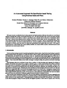


![Download [PDF] Conceptual Database Design: An ... - Google Sites](https://m.moam.info/img/260x300/download-pdf-conceptual-database-design-an-google-_6478ad99097c474d228d6b4f.jpg)