An Approach to Specify and Test Component-Based Dependable Software∗ Arshad Jhumka, Martin Hiller, and Neeraj Suri Dept of Computer Engineering Chalmers University of Technology 412 96, G¨oteborg, Sweden Email:{arshad,hiller,suri}@ce.chalmers.se
Abstract Components (in-house or pre-fabricated) are increasingly being used to reduce the cost of software development. Given that these components may not have not been developed with dependability as a driver, the components need to be adapted to deal with errors coming from their environment. To achieve this, error containment wrappers are often added to increase the robustness of such components. Adopting a gray-box perspective of software, we first present a modular approach for specifying and verifying embedded software made from components, based on concepts from category theory. This modular approach allows the system designer to check for semantic compatibility. To generate the error containment wrappers needed for adaptation, we subsequently present an algorithm that systematically generates the required wrappers. Using the information obtained through wrapper design, we develop an approach to identify relevant test cases to test individual components. We further exploit the modularity of the specification to identify the relevant test cases to perform testing at different levels of SW abstraction.
keywords: Testing, program analysis, formal methods, wrappers, fault tolerance Contact Author: Arshad Jhumka (student) Email:{
[email protected]} Tel/Fax: + 46 (031) 772 5223/+46 (031) 772 3663
∗
Supported in part by TFR grant and Saab Endowment
1
1
Introduction The functionality and dependability of computer systems is increasingly being defined by the software
(SW) implementing the varied system services. To reduce the high cost associated with the development of reliable SW, components, for example commercial-off-the-shelf (COTS), or from component repositories, are being used, while still having to satisfy overall system/SW dependability requirements. However, these components may not have been developed with dependability as a major driver. Thus, to protect from errors coming from their environment, these components need to be adapted to enhance their robustness. Wrappers1 [17, 7] (more specifically dependability wrappers), used as instances of connectors [8], are used to adapt the components. Error containment wrappers [17]
2
are used to detect and correct erroneous signal values, and they
reflect the new requirements imposed on the input and output signals of a component. For example, Executable Assertions (EA’s) [16, 15], such as preconditions and postconditions, are used to check the validity of the communicated signals, as per the desired signal tolerance specification. Error recovery mechanisms (ERM’s) are subsequently incorporated to aid recovery from erroneous situations. To design the relevant wrappers (input or output) for a component, which sometimes need information internal to the component, [17] used the concept of reflection to capture such internal variables (behavior). In this paper, we adopt a gray-box perspective of a component, i.e., the structure of the component is known but is, however, non-modifiable. For components coming from repositories, such gray-box perspective is valid, given that the original design may have been formally verified and validated, and thus cannot be modified. Therefore, wrappers are usually added for adaptation. However, a gray-box perspective allows the system designer to use implementation knowledge to best design wrappers to protect the system. However, [1] presented some problems associated with component reuse, identifying mismatching assumptions about the nature of both the components and the communicated data as two of the main problems encountered. Thus, when using components for designing dependable applications, there are three main problems, among others, to be solved: (i) ensuring semantic compatibility of the components, (ii) designing the relevant wrappers for component adaptation for fault tolerance, and (iii) testing the wrapped components (the wrappers). For the first problem, semantic checks on the compatibility of the components need to be performed. To achieve this, we will present in Section 4 a modular specification and verification framework, based on concepts of category theory. The second problem mentioned earlier is the problem of designing error containment wrappers. In [12], the authors observed that designing self-checks, such as EA’s, is difficult. We subsequently proved in [11] that design of a class of EA’s, called globally consistent EA’s, is NPhard. More details on global consistency will be presented in Section 6. To overcome this intractability problem, in [11], we presented a heuristic approach that can be used to generate wrappers. 1 2
Dependability wrappers usually consist of an error detection (EDM) and error recovery mechanism (ERM) They can be input or output wrappers depending on whether they are placed at the input or output of the component.
2
For the third problem above, once both input and output wrappers for components are obtained and incorporated in the system, they need to be tested to ascertain their validity, i.e., ensuring that the adapted system behaves according to its specifications. We show how to reuse information from the design of these wrappers to generate test cases. 1.1
Paper Objectives
On the above introduction of overall problem perspectives, our overall contributions are the following: • Specification and verification: Given our component-based design, we formally specify a system using a modular framework based on category theory concepts, and exploit this modularity to perform its verification. This is done to allow the system designer to check for semantic compatibility between different communicating components. The reason for adopting category theory as a basis for formal specification and verification is that it facilitates direct explanation and application of the concepts that we will later develop and to better present the different constraints that components need to satisfy. • Wrapper design: We present an approach for the design of error containment wrappers 3 to be incorporated in the system. • Test case generation: Reuse wrapper design information to generate test cases for testing at different abstraction levels, i.e., unit, integration and system testing. For testing at the unit level (i.e., unit testing at the component), we reuse wrapper design information for that given component to generate the relevant test cases. When components are composed, testing this integration (integration testing) is performed reusing test information based on unit testing. Once all components have been integrated, we perform a system level test by reusing test cases used during unit testing. Our specification approach is similar to that of [4], however our overall approach differs in the following ways: (i) we generate wrappers for components using a heuristic, (ii) we reuse the wrappers as oracle and (iii) our approach is primarily focused on gray-box SW testing, unlike black-box [3] or white-box testing [14]. The heuristic to be presented in Section 6 can be incorporated in a compiler. The benefit of the approach described here is that test case generation can be automated. For gray-box testing, the term gray-box has been used with various connotations. Sometimes, graybox testing is used to mean that both white-box and black-box testing are conducted. In [24], they tested the more complex (the algorithmic part) part of an object-oriented code, based on static metrics, using a gray-box approach. In their paper, gray-box meant that the authors make partial use of the code implementation. Specifically, assume that a complex module is composed of some subsystems. They perform white-box testing to force each subsystem to be executed, which are however treated as black-boxes. Our gray-box (implementation is known but is non-modifiable) approach for automatically 3
We will use the terms wrappers to denote error containment wrappers
3
generating test cases, using wrapper design information to test component-based SW represents a first cut at such attempts. 1.2
Testing Overview
Testing strategies can be classified into two broad categories, namely (i) black-box testing (or specificationbased testing), and (ii) white-box testing (or structural testing). Our gray-box perspective of SW implies that we use partial implementation knowledge to drive black-box testing. The reason for performing black-box testing is many-fold. Primarily, as the target SW is non-modifiable, EA’s, which are known to enhance SW testability [21], cannot be inserted in the SW. This hindrance imposes determination of the correctness of the component only through its behaviors, i.e., based on the specification. The intent of this paper, as far as testing is concerned, is to reuse the information pertaining to the design of those error containment wrappers (EA’s) to identify relevant test cases for partition testing [20]. Partition testing works by partitioning the input space of the program or component into subsets, and test cases selected from each subset. We solve the oracle problem by using the output wrapper of the component or system as oracle. We also argue that test cases derived from component specifications may not provide sufficient coverage, especially if some important recovery mechanisms are incorporated to recover from erroneous system behavior. Paper Organization: Section 2 present the system and fault model we use in the paper. Section 3 presents the example we will use to illustrate our framework. Our framework for modular specification is presented in Section 4. We subsequently present our algorithm for generating wrappers in Section 6. Section 7 presents our approach to generating test cases, based on wrapper design information. Section 8 provides examples on how testing is performed at various abstraction levels. Section 9 discusses our approach and we describe areas for future research.
2
System and Fault Models System Model: We assume a system consisting of different SW components, communicating with
each other via signals (we use the term “signals” as an abstraction whose implementation could be via message passing, parameter passing, shared variables, etc). The components may run on the same processor or may be distributed. Each component consists of an import, export interface, a parameter and a body part. The import and export interfaces refer to the services needed and provided by a component. The body part implements the services that are exported by the component, by using resources obtained from its environment. The parameter part introduces the domains used by the system (Fig. 1). Fault Model: Our system is driven by information exchange across components (import and export). Thus, we are interested in determining which inputs that are liable to introduce data errors into the system or components that will cause violation of the specification of the system. A data error may be, for example, a signal value which is outside a specified bound. Errors may occur at system input level or at component level. Thus, we need to test each component as well as the system to ensure proper
4
behavior, both during operational and faulty scenarios.
3
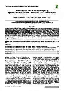
An Example System In this section, we will present a small example that we will use through out the paper to explain
the different concepts. Assume the system is composed of two components, as in Fig. 1. The first component, C1 reads sensor values from two different sensors, and then passes the difference between those two sensor values to the second component, C2 , which then calculates a value that will be sent as output to an actuator. body import sensor1 sensor2
diff
C1
C2
output
export
Figure 1: An example target system
The implementations of the two components are presented here: Component C1
Component C2
Component C1
Component C2
Private sensor1,sensor2,difference : Signal;
Private diff,output : Signal;
Export get-difference();
Export outputvalue();
void private read-sensor1()
Import get-difference();
{ sensor1 := sensor1value;
void public outputvalue()
return();}
{ diff := get-difference();
void private read-sensor2()
newval := diff * 2;
{ sensor1 := sensor2value;
output := newval + diff;
return();}
return();}
void private calc-diff()
End Component
{ read-sensor1(); read-sensor2(); difference := sensor1 - sensor2; return();} Signal public get-difference() { calc-diff(); return(difference);} End Component
Also, we assume that from the specification of the above system, the value of the system output, output should be (0 ≤ output ≤ 30).
5
4
A Modular Specification Framework Our modular specification framework is based on the concept of category theory [5]. As mentioned
in the introduction, we chose category theory as it provides the necessary formal foundation to present our testing framework. Components are algebraically specified4 , and they can be interconnected to form bigger components. The composition operation then defines and constructs an aggregrated component describing the overall system from the individual components and their interactions. 4.1
Definition of a Component Using Category Theory
A specification consists of two parts:(a) a signature part, and (b) an axiom part. The signature introduces syntactical elements that are used in the axiom part, and consists of three parts: (a1) Sorts part declares the domains, (a2) Constants (resp. Variables) part declares the time independent (resp. time dependent) functions and/or predicates, and (a3) an Action part declares predicates and functions representing event instances. The axiom part defines the behavior of the system as well as constraints on environments. The axiom part may express conditions such as pre- and postconditions. To capture the time-varying behavior of a system, the axioms can be formulated as TRIO formulas [13], which capture the dynamic aspects of systems. TRIO logic is well adapted to deal with real-time constraints, as they are based on a metric representation of time. More details on TRIO are provided in Section 4.2. Each component is then made up of four specifications and four specification morphisms. The four specifications are (i) the parameter (PAR), (ii) import (IMP), (iii) export (EXP), and (iv) body (BOD) specifications(see Fig. 2). The parameter (PAR) part of the component contains the parameters of the component, and it also identifies the elements shared by the export (EXP) interface and import (IMP) interface. The import (IMP) interface identifies all resources that are needed by the component that are defined by its environment. Constraints on what is imported can be specified in the axiom part of the import interface of the component. The export (EXP) interface contains resources made available to the environment by a component. Any constraint on what is exported can be similarly specified as axioms. The body (BOD) part defines how the resources imported from the environment are used to implement the resources to be exported by the component. It presents the complete description of the component, however the details are not available, i.e., they are hidden (encapsulated). In the next section, we will briefly introduce the TRIO language. Further, we will use our example target system of Section 3 to demonstrate how systems are specified and verified. More details on TRIO logic are found in [13]. 4.2
TRIO Logic Specification
The TRIO [13] language is an extension of classical first-order temporal logic: the meaning of a TRIO formula is not absolute, but is given with respect to a current, implicit time instant. Timing 4
This is a realistic assumption since components can be selected and retrieved based on specification [23]
6
e
PAR i
EXP
Component Ci
IMP
v
BOD
s
Figure 2: A component with four specifications and associated morphisms
requirements are specified using two basic operators, namely Futr and Past, which refer to time instants whose distance, in the future or past, is specified precisely and quantitatively. Using these operators, more complex operators can be constructed, such as Always etc. The reason for using TRIO logic over classical temporal logic (TLA) is that executable assertions (EA’s) [16] are usually inserted to monitor signal values, which are usually time-dependent. The TRIO language is a typed first order logical language extended with temporal operators. The alphabet of TRIO is composed of sort, logical variable, function/predicates names, and usual propositional connectives, and the existential quantifiers, ∃ and ∀, and hence more complex temporal operators and properties may be expressed. For example, to specify that a property P will hold at all other future time instant, this may be specified as follow, i.e., Always(P): Always(F) = ∀d(d > 0 ↔ F utr(F, d)). In the next section, we will use the example target system to explain how (i) the specification and (ii) verification of the system are performed.
5
Specification and Verification of the Example System In this section, we will use explain how the concepts of category theory presented in the previous
section are used to specify and verify a system. In our example system from Section 4, the component C2 imports (respectively, exports) a method called get-difference() (outputvalue()).
C2 Import Spec:
C2 Export Spec:
Sorts :
Sorts :
Signal: Int
Signal: Int
Actions:
Actions:
get-difference() : → Signal
outputvalue() :
Axioms:
Axioms:
Always(∃y : y = get-difference() );
Always(∃y : y = outputvalue());
End Spec
End Spec
7
→ signal
The import (respectively, export) interface introduces the entities imported (exported) by the given component. In this case, C2 imports (exports) one given function, get-difference() (outputvalue(), which are part of the action section of the specification. Given that the value returned is of type Signal, in the sort part, which introduces the relevant domains, we introduce the domain Signal. Finally, the axiom part expresses the fact that a value can be imported (respectively exported) at any time instant from get-difference() (outputvalue()). In our import and export specifications, no constant or variable was declared. The parameter (PAR) part and the body (BOD) of component C2 are shown below:
C2 PAR Spec:
C2 BODY Spec:
Sorts :
Sorts :
Signal: Int
Signal: Int;
End Spec
Variables: diff, output: Signal; Actions: get-difference() : → Signal outputvalue :
→ signal
Axioms: Always(∀y : y = get-difference() ↔ dif f = y); Always(∀y : y = outputvalue() ↔ output = y); End Spec
The parameter (PAR) part introduces the entities common to the export and import interface, in this case, the type Signal. The BODY part of the component specification contains the union of all sorts and actions defined in the IMP and EXP interfaces of the component. Overall, we have specified component C2 where values imported and exported are not constrained, as specified by the axioms since it may not be fault tolerant. As the different interfaces have been specified, specification morphisms link all these specifications together to form a component specification. Specification Morphism: A specification morphism m : A → B from a specification A to specification B maps any element of the signature of A to an element of the signature of B that is compatible (i.e., sort with sort etc) The four specification morphisms e,i,s,v (Fig. 2) of the component describe the links between the four specifications (PAR,IMP,EXP,BOD). For verification, one important aspect of specification morphisms is that they preserve axioms. For example, considering morphism v of component C 2 , one must prove that the axioms defined in the export interface of C2 can be deduced from those defined in the body specification of C2 . Behaviorally, this means that the behavior of A is preserved in B. This proof can be done either automatically or via theorem provers. Also, the specification morphisms ensure that no conflict exists in the specifications, such as importing a non-existing resource. As example, we provide the definitions for morphisms s and v for component C2 of our example. 8
Morphism s of C2 :
Morphism v of C2 :
Sorts :
Sorts :
Signal → Signal
Signal → Signal
Actions:
Actions:
get-difference() : → get-difference()
outputvalue() : → outputvalue()
What the above means is that the Signal domain is the same in both the import (respectively, export) and body specifications, and that the function get-difference() (respectively, outputvalue()) function needed (exported) by the body (export) specification is indeed provided by the import (body) interface. 5.1
Component Composition
Once components are specified and verified, interactions between different components can be specified using the composition operation, as detailed below. Given two components Ci (component importing services) and Ce (component exporting the services) such that all elements imported by Ci are exported (defined) by Ce , the composition operation builds a component Cie . From our example, it means that if all the resources (imported entities) required by component C2 are provided by component C1 , then these two components (C1 and C2 ) can be composed together to form a bigger component C21 . To ensure this, we define a component morphism to map the resources required by component Ci to the those provided by component Ce . For example, we define a component morphism mapping resources needed by C2 to the resources provided by C1 . EXP i
PARi C i
hp
BOD i
IMP i h PARj
EXP j
b’
Cj IMP j
BOD j
BOD b’’
ij
Figure 3: Composing two components
A module morphism is a pair (h, hp) (see Fig 3) of morphisms such that h associates data imported by Ci to data exported by Ce . Morphism hp maps parameter part of Ci to those of Ce . The component Cie can then be computed as the pushout [5] of components Ci and Ce , i.e., the bigger component imports what component Ce imports, exports what component Ci exports. If components Ci and Ce and morphisms h and hp are correctly defined, then component Cie is correct. Informally, this means 9
that if the behavior of each component is preserved (i.e., components correctly defined), and the resource associations are right (morphisms correctly defined), then the resulting component is correct. From our example, the behavior of C1 is preserved in C2 , and also the resources needed by (imported) C2 are provided by C1 , meaning that these two components C1 and C2 can be composed together. As example, we provide the export interface of component C1 and the associated morphism h required for resource associations. We match the export interface of C1 with the import interface of C2 (see Section. 5), resulting in morphism h.
C1 Export Spec:
h morphism:
Sorts :
Sorts:
Signal: Int
Signal → Signal
Actions:
Actions:
get-difference() : → Signal
get-difference() → get-difference()
Axioms: Always(∃y : y = get-difference()) End Spec
5.2
Verification Issues:
We make use of the component morphisms to perform both verification and testing. During composition, one of the main aspect is that of non-interference across components. This implies that all axioms defined in an importing component Ci are preserved by an exporting component Ce . Formally, this means that axioms defined in Ci are translated along morphism h into theorems in Ce that need to be proved. Ability to discharge such proofs guarantee safe composition of C i and Ce . From our example, we need to show that we can prove the axiom defined in the import specification of C 2 from those defined in the export specification of C1 . We also make use of the morphism h to perform integration testing. Test cases use to perform unit testing on component Ci are translated as output from component Ce along h. For testing, we require the morphisms to be injective. At this point, we have shown how to specify and verify a component-based development of software, using concepts from category theory. We incrementally showed, by use of a small example, how a component is composed from four basic specifications, and how component specifications can be combined into bigger components through component morphisms. We also showed how axioms (i.e., properties) of specifications can be specified in TRIO logic, which we briefly introduced in Section 4.2. The aim of testing is to ascertain that the different axioms defined in a given component are not violated, i.e., the behavior of the component conforms to its specified property, as defined by TRIO formulas. In the next section, we provide a brief explanation of how TRIO formulas can be tested, i.e., testing the components. 10
5.3
Testing Issues
For testing purposes, two definitions are provided, and are taken from [13]. Definition 1: An event is a pair (L, i) where L is a ground literal of a time-dependent predicate and where i is a time instant belonging to the time domain. A history is an event set that does not include the events (L, i) and (¬L, i). A history is complete if it contains a unique truth value for each predicate of the formula at each time instant of the time domain. A complete history satisfies a formula F at time t if its evaluation in which predicate values are defined by the events in the history yields a TRUE value. The behavior of a system is characterized by TRIO formulas. Therefore, to test the behavior of a system, TRIO histories can be used as test cases. Definition 2: A test case for a given TRIO formula F is a complete history that satisfies F at one or more time instants of the time domain. TRIO is executable, hence its formulas can be automatically checked for validity. During interpretation of a given formula F , behaviors of the specified system compatible with F are generated, and they are histories, and these histories can be used as test cases. Such test cases can be used to test the system under normal operational scenarios. For example, if we want to test the first axiom defined in the body specification of component C 2 of our example, a history can be as follows5 :
TestCase-Hist-01-C2 ((get-difference() = 10),1) ((diff = 10), 1) ((output = 30),1) End
In fault-free scenarios, a program always satisfy its specification (given that it was formally verified, as we showed earlier). However, when there is an error in the system, a program’s behavior may violate its specification. Thus, testing a program only to ascertain its behavior under fault-free scenario is inadequate (as mentioned in one keynote speech at HASE 2001). Thus, testing the system with test cases that can cause violation of some properties of the program need to be performed, so as to ascertain the behavior of the system under such conditions, i.e., test whether the program is fault-tolerant. Testing behaviors of the program under faulty scenarios give rise to some problems: (i) What characterizes erroneous data for a given component or system?, (ii) how do we generate such test cases, for each component, and for the entire system?, (iii) can such test case generation be automated? As mentioned in the introduction, to make a system fault tolerant, we add dependability wrappers. Thus, our approach to tackle the above problems is to first generate the wrappers, and then reuse the 5
We will use constants, rather than variables, in our examples to represent a certain given value.
11
knowledge obtained from wrapper design to generate test cases. To automate generation of test cases implies automatic generation of wrappers. When wrappers are incorporated in the system, the behavior of the different components is constrained (through addition of more axioms). Thus, we endeavor to test the different added axioms, i.e., test whether the property of the fault tolerant program still satisfies the program’s specification in presence of faults. We emphasize that our method is not intended to bypass white-box and black-box testing strategies, which are needed to test the initial program. However, our approach targets generation of test cases as a complement to already existing techniques, by providing additional test cases for testing the wrappers. In subsequent sections, we will highlight the complementary aspects of our approach.
6
Design of Wrappers: Consistency Conditions In SW, Executable Assertions (EA’s) are usually incorporated to monitor signals so as to detect
any erroneous values. However, design of EA’s placed in the SW, especially when functionalities are distributed over different components, is problematic, as explained in [12]. In [11], we introduced the concept of global consistency of EA’s. Two EA’s, EAi and EAj , are consistent with each other if the code relating them, FM , is such that FM transforms EAi into EAj , i.e., the set of values accepted by EAi is transformed by FM into the set of values accepted by EAj . The intent was to design a set of localized EA’s (EA’s that are placed in individual components) such that all EA’s are globally consistent, i.e., they are all consistent with respect to the safety specification [2] of the system, where the safety specification defines a set of bad computation prefix that should not appear in a given execution of the program. We have shown in [11] that design of those globally consistent EA’s is NP hard. We thus provided a heuristic approach that, given the safety specification of the system, systematically generates the globally consistent EA’s for each component. The heuristic works in a way analogous to predicate transformers, through backtracking. Informally, the algorithm works as follows: it takes the safety specification of the system as input, together with the SW architecture. The main steps of the algorithm are: Step 1,2 The algorithm starts at the end of the sink module and backtracks to its start. Then, the process is performed for every component. Step 3 All conditions for computing the different values of variables are calculated. Program slicing [19] techniques can be slightly modified and used to achieve that. Step 4 Once all conditions for computing the different variables are obtained, they are substituted in the condition for computing the output signal. For example, suppose we have an output signal X and the condition for computing its value is X := Y + 1. Suppose that the condition for computing Y is Y := Z + 2, where Z is the input. Then, the new condition for X is X := Z + 2 + 1 = X := Z + 3. Step 5 This new condition is substituted in the postcondition defined on the output signal (say X), and by simplifying the constraint thus obtained, we can obtain a constraint defined on the input signal (say Z). This constraint will be the precondition in the given module.
12
Step 6 This precondition is translated into the postcondition of the preceding module. Formally, we translate this precondition along morphism h to obtain the postcondition on the preceding module. Step 7+ The same procedure is iterated until the source components are reached, and constraints on system inputs obtained.
Thus, the algorithm implementation is as following:
Derive_EA(, , ) { 1
while (NOT beginning of ) {
2
for (all variables V in )
3
conditions(V) := determine_from_module();
%Conditions for computing variable V determined from module } 4
conditions() := get_all_conditions();
%All conditions for computing output signal 5
new_preconditions := output_EA[conditions(OutputSignal)/OutputSignal];
%new preconditions obtained by substituting output signal by the condition obtained 6
postcond_preceding_module := new_preconditions;
%preconditions translated as postconditions in preceding module 7
preceding_module := get_id_preceding_module(module_interconnections, module_name);
%gets the id of the other module with which module_name is communicating 8
if (preceding_module == NIL) break;
%source module reached 9
Derive_EA(postcond_preceding_module, preceding_module,module_interconnections); }
It generates input and output wrappers for each component upon backtracking. When a component Ci imports services exported by another component Ce , the input wrapper defined in Ci is transformed into an output wrapper in Ce . Formally, the input wrapper in Ci is translated along morphism h into an output wrapper in Ce . Formally, we make use of the component morphisms to generate globally consistent EA’s. As EA’s are transformed, and input wrappers generated, we make use of such wrapper design to generate test cases. The wrappers (input and output) developed for each component are added to the axiom part of the component specification, expressed in TRIO logic. As mentioned in Section 3, the safety specification of the example target system is (0 ≤ outputvalue ≤ 30)6 . Running the above heuristic on the program given in Section 3, we obtain the following wrappers for each component for detecting errors:
Input and output wrappers for C2
Input and output wrappers for C1
(1) 0 ≤ output ≤ 30 (output wrapper)
(1) 0 ≤ dif f erence ≤ 10 (output wrapper)
(2) 0 ≤ get−dif f erence() ≤ 10 (input wrapper)
(2) 0 ≤ ( read-sensor1() − read-sensor2() ) ≤ 10 (input wrapper)
6
The safety specification is provided by the system designer during specification phase.
13
Thus, including these wrappers in the original program transforms it into a fault tolerant program. For example, including the output (respectively, input) wrapper in the export (import) specification of component C2 will result in the following new specifications for the import and export interfaces (compare with Section 5):
C2 Import Spec:
C2 Export Spec:
Sorts :
Sorts :
Signal: Int
Signal: Int
Actions:
Actions:
get-difference() : → Signal
outputvalue() :
Axioms:
Axioms:
Always(∃y
:
0 ≤get-difference()≤ 10 ∧ y
→ signal
Always(∃y : 0 ≤ outputvalue() ≤ 30 ∧ y = output-
= get-
difference() );
value());
End Spec
End Spec
Thus, these wrappers will ensure that the safety specification of the system is not violated by detecting erroneous signal errors coming from component C2 ’s environment. The added axioms are underlined. In the next section, we will present how test cases can be generated using the information generated from the above wrappers.
7
Test Case Generation Using Wrapper Information We have presented an approach for specifying and verifying component-based fault intolerant SW.
We also argued that for fault tolerance purposes, such programs need to be adapted to make them tolerant to errors from their environment by adding wrappers. We presented in [11] a heuristic that can systematically generate such globally consistent wrappers, exploiting the component morphisms. In this section, we will explain how to systematically reuse wrapper design information to systematically partition the input space of both the components and system to obtain relevant test cases for testing. As mentioned earlier, our overall objective is systematizing and automating test case identification to aid testing the robustness of the adapted software. 7.1
Partition Testing: An Overview
Partition testing refers to a very general family of testing strategies [20]. It works by partitioning an input space into sub-domains, with the tester selecting one or more elements from each sub-domain, depending on the criteria and coverage required. The idea behind partition testing is to divide the input domain in such a way that, within each sub-domain, either the program behaves correctly or the program fails. Such sub-domains are sometimes called revealing or homogeneous. In many cases for embedded SW, specification for a given input signal partitions its input space into two sub-domains, i.e., one sub-domain satisfying the precondition defined on the signal and the other one not. However, we argue that partitioning the input space of signals into two such sub-domains is limited, 14
since it does not take into account subtle interactions within a component. For example, consider the input wrapper generated for component C1 , (0 ≤ (sensor1 − sensor2) ≤ 10). Assume that specification of component C1 of our example states that a precondition on signal sensor1 in C1 should be greater than 25. However, from the input wrapper for C1 , even if the value of sensor1 is less than 25 (which implies violation of the precondition), if the difference between sensor1 and sensor2 is less than 10, then there will be no safety specification violation. Hence, we argue that our wrappers better capture the interaction between signals than preconditions obtained from specification, which thus partitions the input space differently. This is crucial, as partitioning an input space in the wrong way will cause the tester to wrongly test the system. To better illustrate this, assume the following specification-based preconditions defined on the input signals of component C1 : Preconditions defined on input signals of C1 : (sensor1): sensor1 ≥ 25 (sensor2): sensor2 ≤ 20
Assume that at a given time t, sensor1 has value 24 (which violates its precondition) and sensor2 has value 21 (violating its precondition). However, from these values, the output signal from component C 2 will have value 9, which satisfies the safety specification (0 ≤ output ≤ 30), though the input signals violated their preconditions. What this means in terms of testing is, if such a test case was used to test the system, it would give the impression of the system being fault tolerant (since the safety specification of the system was not violated when there was an error in the system inputs), when the wrong tests have been perfomed, i.e., wrong test case chosen. Hence, we show that specification-based preconditions are limited. This observation is shared by [12]. However, our wrappers generated fully captured the relationship between the different signals. Thus, we propose to reuse information obtained from wrapper design to partition the input space. Consider a component as in Fig. 4 (top). The module contains two inputs, I1 and I2 . Their respective input space is partitioned into an OK and a BAD partition (Fig. 4 (bottom)). Assuming a uniformity [9] criteria, we may select one value randomly from each subdomain, and obtain a set of test cases for the component, since every test case in a given subdomain will test the system in the same way (uniformity criterion). However, understanding the interactions within the component is crucial, since it will cause partitioning of the input space of the component differently, and, thus, may result in generating more appropriate test cases, (see Fig. 5 (bottom)). We argue that testing based only on specifications defined on input signals is limited. Another advantage of using the wrapper design information in test case generation is that the input wrapper is an instance of an assertion. In [20], it was shown that, for partition testing to be efficient, there is a need to group within one given partition all inputs that will cause the system to fail. Using the wrapper information, the tester can group all such input combinations that will violate the wrapper 15
constraints within one sub-domain, thus satisfying a criterion for optimality from [20]. Thus, it means that using our approach, performance of partition testing is optimized. Specifically, from our example, whenever (sensor1−sensor2 > 10), the tester is able to group exactly those input combinations that may cause the system to fail. Thus, reusing wrapper information will optimize the partition testing strategy. Techniques for testing exception handling [18] constructs are mainly based on whitebox knowledge, and may not be applicable in our context. I1 I2
I1
I 2
O 1
Ci
OK
BAD input space of I 1 and I 2
OK
BAD
Figure 4: Partitioning the input space of a module
I 1 O1 I 2
I2 BAD OK I 1
Figure 5: Partitioning the input space of a module uwing wrapper information
8
Unit, Integration and System Testing In this section, we will explain how our framework deals with testing at different levels, i.e., unit,
integration and system level testing. 8.1
Unit Testing
In this section, we are interested in performing unit testing, i.e., testing of each component. Given that we cannot have access to modify the source code, the tester cannot insert assertions in the code to improve testability [21]. Also, given that different components have been wrapped with error containment 16
wrappers, we focused on testing the wrappers such that each wrapped component satisfies the required specification, that is, we endeavor to test those axioms that have been added to the axiom part of different specifications (e.g., import interface etc). As mentioned earlier, we specifically want to test the wrappers that have been added for fault tolerance, i.e., the axioms that have been added. To exactly show how this is achieved, we will develop different test cases, using our example from Section 3.
TestCase-Hist-01-C2
TestCase-Hist-02-C2
((get-difference() = 5), 1)
((get-difference() = 15),1)
((diff = 5),1)
((diff = 15),1)
((output = 5),1)
((output = 45),1)
End
End
As mentioned in Section 4, under normal operation, test cases can be obtained from TRIO model generator, as histories. Choosing the Hist-01-C2 test case, and then running TRIO will result in TRIO accepting the above as a possible history, i.e., this test case can be used to test the system for proper functioning, i.e., during no fault scenario. In other words, Hist-01-C2 can be generated by TRIO model generator as a possible history (test case). A series of such test cases may be obtained from TRIO. Let the set consisting of such test cases be denoted by Sg Now, during faulty scenario, the system may behave in a different way, and the wrappers added in each component need to be tested. Thus, additional test cases, not in set S g , need to be generated, and these test cases cannot be obtained from TRIO, since these situations are not histories. We thus reuse the information from the wrapper to generate such test cases. For example, following from our running example, a test case Hist-02-C2, for testing the wrappers in component C2 , is generated. Running test case Hist-02-C2 above will indicate how the system will behave. We have shown that the value from get-difference() should be between 0 and 10. A value of 15 from get-difference () in test case Hist-02-C2 will cause a violation of the axiom placed in the import interface of component C 2 . The above test case represents a case where there is an error in the system. If the value returned by C 2 satisfies its output wrapper, then C2 satisfies its specification during faulty situations, i.e., is fault tolerant. For component C1 , we give a test case Hist-03-C1 obtainable from TRIO model generator (i.e., which is in set Sg ) and then we also explain how a test case Hist-04-C1 testing the wrappers may be generated from the wrapper information of C1 . Since (0 ≤ read-sensor1 − read-sensor2 ≤ 10), we choose values of sensor1 and sensor2 that will violate this constraint, thus we obtains Hist-04-C1
17
TestCase-Hist-03-C1
TestCase-Hist-04-C1
((read-sensor1 = 27), 1)
((read-sensor1 = 30),1)
((read-sensor2 = 20),2)
((read-sensor2 = 15),1)
((sensor1 = 27),1)
((sensor1 = 30),1)
((sensor2 = 20),1)
((sensor2 = 15),1)
((difference = 7),1)
((difference = 15),1)
End
End
Test cases may contain internal items, i.e., internal variables, and they cannot be included in the test cases since they are hidden (encapsulated). Thus, we need to project these test cases on the interfaces (import and export) of the given component. Test cases Hist-03-C1 and Hist-04-C1 for component C 1 are transformed into test cases Hist-05-C1 and Hist-06-C1 respectively, below by removing any internal variables sensor1 and sensor2.
TestCase-Hist-05-C1
TestCase-Hist-06-C1
((read-sensor1 = 27), 1)
((read-sensor1 = 30),1)
((read-sensor2 = 20),2)
((read-sensor2 = 15),1)
((difference = 7),1)
((difference = 15),1)
End
End
For component C2 , projecting the test cases Hist-01-C2 and Hist-02-C2 on its interface will result in removal of the diff variable from the test case, resulting in test cases Hist-07-C2 and Hist-08-C2 respectively:
TestCase-Hist-07-C2
8.2
TestCase-Hist-08-C2
((get-difference() = 5), 1)
((get-difference() = 15),1)
((diff = 5),1)
((diff = 15),1)
((output = 5),1)
((output = 45),1)
End
End
Integration Testing
Integration testing aims at testing the links between two components. A link is specified as an injective morphism between two specifications. Formal verification implies that all behaviors of component Ci is preserved by component Ce , i.e., all axioms of Ci are translated along morphism h as theorems in component Ce , that need to be proved. So, a test goal of integration testing is to test the image of the new axioms added in the specification of component Ci . Specifically, from our heuristic, since input wrappers in Ci (component importing services) are transformed into output wrappers in component C e
18
(component exporting services), we need to test that data communication between these two communicating components do not violate the input wrapper constraints of the C i . That is, data that satisfies the output wrapper constraint of Ce should not violate the input wrapper constraint defined in Ci . Thus, the test cases generated for unit testing the component Ci can be reused, with the only change being that items are renamed under morphism h. For example, when testing the import interface of component C2 , all elements in that test case are projected onto corresponding elements as defined by morphism h. Specifically, test case Hist-09-C2-Imp tests the import interface of component C 2 . For integration testing, we want to test the values coming from component C 1 , i.e., testing C1 ’s export interface. As example, Hist-09-C2-Imp is transformed under morphism h to test case Hist-10-C1-Exp, that tests the export interface of component C1 , i.e, get-difference() maps onto get-difference() whereas output maps to nothing, and so is removed from the test case.
TestCase-Hist-09-C2-Imp
TestCase-Hist-10-C1-Exp
((get-difference() = 5), 1)
((get-difference() = 5),1)
((output = 15),1)
((get-difference() = 10),2)
((get-difference() = 10),2)
End
((output = 30),2) End
8.3
System Level Testing
In system testing, we aim at testing the whole system and we perform black-box testing. In such cases, for system level testing, we use the safety specification defined on the system as oracle. There are two possible ways to generate test cases for system level testing. One is for the TRIO model generator to generate the test cases. Unfortunately, TRIO model generator is not very suitable for generating test cases for large systems. Thus, we choose the second option, which aims at reusing test cases generated during unit testing. Specifically, in Section 5.1, we mentioned that during composition, the bigger component C21 acquires the import interface of the component C1 , and the export interface of the component C2 . To perform system testing, we need to reuse test cases used for unit testing component C1 . Test case Hist-05-C1 was used to test component C1 . However, during system testing, C1 ’s export interface disappears, and we project the given test case over the interface of the larger component C21 , obtaining test case Hist-11-C21, i.e., we remove any element that relates to the export interface of component C1 . Hence, we reuse test cases from unit testing, and we only need to project them on the relevant interfaces to obtain the relevant test cases for system testing. Also, given that the safety specification has been defined on the system, the tester can use it as an oracle during system testing, where the oracle is an omniscient entity that says whether the result of a test is good or not.
19
TestCase-Hist-05-C1
TestCase-Hist-11-C21
((read-sensor1 = 27), 1)
((read-sensor1 = 27),1)
((read-sensor2 = 20),2)
((read-sensor2 = 20),1)
((difference = 7),1)
End
End
Given that we need to test for fault tolerance of the overall system as well, we reuse test cases that were used for fault tolerance testing of component C1 , and project the test cases on the interface of the bigger component. For example, such a test case was Hist-06-C1. Projecting it on the interface of component C21 results in test case Hist-12-C21.
TestCase-Hist-06-C1
TestCaseHist-12-C21
((read-sensor1 = 30), 1)
((read-sensor1 = 30),1)
((read-sensor2 = 15),1)
((read-sensor2 = 15),1)
((difference = 15),1)
End
End
Overall, we have explained why test cases that test for fault tolerance cannot be generated from TRIO model generator. Thus, to tackle this problem, we gave showed how information from wrapper design can be systematically reused to generate the test cases for fault tolerance testing. As mentioned earlier, our approach for generating test cases from wrapper design information complements the test case generation for normal operation from TRIO.
9
Discussion and Future Work Overall, in this paper, we have made the following contributions: 1. We have presented a framework for specifying and verifying a component-based SW to ensure semantic compatibility across components (Sec. 4, Sec. 5), 2. We presented a heuristic for generating globally consistent EA’s (wrappers) with respect to the safety specification of the system to increase the robustness of software(Sec. 6), 3. We have illustrated through examples how we make use of wrapper design information to automatically generate test cases for testing of components at various levels (unit, integration and system), and we systematically exploit the modularity structure of the specification to perform integration testing. For system level testing, we reuse test cases generated for unit testing (Sec. 7 and Sec. 8). We have showed that testing a system under normal operational conditions is not adequate. As TRIO
model generator cannot automatically generate the test cases for faulty scenarios (nor for large systems), we have addressed this problem by reusing the desing information of wrappers used for increasing the robustness to generate the test cases. 20
Most work on testing has covered two broad categories, namely white-box and black-box testing. Our work covers gray-box testing at the level of components. Our technique is intended to test software built from components, whose internals are not available for modifification by the designer, but which can be compiled. Also, to the best of our knowledge, little work has addressed the automatic generation of wrappers, and consequently the generation of test cases for testing the robustness of the system. Also, our approach has the property that it partitions an input space into such sub-domains where all inputs that can force the system into an erroneous state are grouped together. Using partition testing, this ability of partitioning the input space as such results in very efficient testing (in fact, optimal). Thus, test cases for unit, integration and system level testing can be generated, and these test cases provide more insight into how to perform the partitioning of the input space. We argue that testing based on test cases generated from functional specification, especially for component-based SW, are insufficient to test the system given that they fail to completely capture subtle dependencies. Overall, we envision our approach to complement existing testing approaches. A tool exists where the module calculus was extended in [22] to TRIO [13] logic specifications to capture the dynamic aspects of systems. As future work, we are planning on using our framework on a real target system, with the intention of testing conformity of wrappers, and of ascertaining that the overall system conforms to the safety specification defined on the system.
References [1] R. Allen, D. Garlan and J. Ockerbloom, “Architectural mismatch or why it’s hard to build systems out of existing parts”, Proc. ICSE 94, pp. 179–185. [2] B. Alpern, F.B. Schneider, “Defining Liveness”, Information Processing Letters, 21(4):181–185, 1985 [3] B. Beizer,“Black Box Testing: Techniques for Functional Testing of Software and Systems”, John Wiley, New York, 1995 [4] M. Doche, C. Seguin, V. Wiels, “A Modular Approach to Specify and Test an Electrical Flight Control System”, 4th Intl. Workshop on Formal Methods for Industrial Critical Systems, 1999 [5] H. Ehrig, B. Mahr, “Fundamentals of Algebraic Specification 2: Modules Specifications and Constraints”, EATCS Monographs on Theoretical Computer Science, Vol. 21, Springer Verlag, 1989 [6] A. Ermedahl, J. Gustafsson, “Deriving Annotations For Tight Calculation of Execution Time”, Proc EuroPar’97, RT System Workshop, pp. 1298–1307 [7] T. Fraser, L. Badger, and M. Feldman, “Hardening cots software with generic software wrappers”, IEEE Symposium on Security and Privacy, pp. 2–16, 1999 [8] D. Garlan, R. Allen, “Formalizing architectural connection”, Proc. ICSE, pp. 71–80, 1995 [9] M.C. Gaudel, “Testing can be formal, too”, Proc. TAPSOFT’95, LNCS 915, pp. 82–96, 1995 [10] M.J. Harrold, M.L. Soffa, “Selecting and Using Data for Integration Testing”, IEEE Software, 8(2):58–65, March 1991. [11] A. Jhumka, M. Hiller, V. Claesson, N. Suri, “On Systematic Design of Consistent Executable Assertions for Distributed Embedded Systems”, To Appear, ACM Joint Conference LCTES/SCOPES’02
21
[12] N.G. Leveson, S.S. Cha, J.C. Knight, T.J. Shimeall, “The use of self checks and voting in software detection: An empirical study.”, IEEE Trans. on Soft. Eng, 16:432–443, 1990 [13] D. Mandrioli, S. Morasca, A. Morzenti, “Generating Test Cases for Real-Time Systems from Logic Specifications”, ACM Trans. Computer Systems, Vol. 13, No. 4, pp. 365–398, Nov. 95 [14] S. Ntafos, “A Comparison of Some Structural Testing Strategies”, IEEE Trans. Soft Eng., Vol. 14, No. 6, pp. 868–874, 1988 [15] D. Rosenblum, “A practical approach to programming with assertions”, Trans. on Software Engineering, 21(1):19–31, 1995. [16] S. Saib, “Executable assertions - an aid to reliable software”, Proc. Asilomar Conference Circuits Systems and Computers, pp. 277–281, 1978 [17] F. Salles, M. Rodriguez, J.C. Fabre, and J. Arlat, “Metakernels and Fault containment wrappers”, Proc. FTCS, pp. 22–29, 1998 [18] S. Sinha, M.J. Harrold, “Criteria for Testing Exception-Handling Constructs in JAVA”, Technical Report OSU-CISRC-6/99-TR16, 1999. [19] F. Tip, ”A Survey of Program Slicing Techniques,” Journal Prog. Languages, Vol.3, No.3, pp.121– 189, Sept. 95 [20] B. Jeng, E.J. Weyuker, “Analyzing Partition Testing Strategies”, IEEE Trans.Soft Eng, 17(7):703– 711, July 1991. [21] H. Yin, J. Bieman, “Improving Software Testability with Assertion Insertion”, Proc. International Test Conference, pp. 831–839, 1994 [22] v. Wiels, “Modularite pour la conception et la validation formelles de systemes”, PhD thesis, ENSAE - ONERA/CERT/DERI, Oct 97 [23] A.M. Zaremski, J.‘Wing, “Specification Matching of Software Components”, 3rd ACM Symp. on Foundations of Soft. Engg, pp. 6–17, October 1995. [24] J. Zhuo, P. Oman, R. Pichai, S. Sahni, “Using Relative Complexity To Allocate Resources In GrayBox Testing Of Object-Oriented Code”, Proc.4th Intl Software Metrics Symposium, pp. 74–81, 1997
22