Proceedingsofofthe theASME ASME2009 2009International InternationalDesign DesignEngineering EngineeringTechnical TechnicalConferences Conferences&& Proceedings Computersand andInformation InformationininEngineering EngineeringConference Conference Computers IDETC/CIE2009 2009 IDETC/CIE August 30 September 2, 2009, San Diego, California, USA August 30 - September 2, 2009, San Diego, California, USA
DETC2009-86752 DETC2009-86752 AN APPROACH TO SUPPORT THE IMPLEMENTATION OF PRODUCT CONFIGURATION TOOLS Maura Mengoni Ferruccio Mandorli
Roberto Raffaeli∗ Michele Germani
Department of Mechanical Engineering, Polytechnic University of Marche, Ancona, 60131 ITALY ABSTRACT Companies applying mass customization paradigm regard the design process as a configuration task where the solution is achieved through the extraction of a new instance from a modular product structure. In this context product configuration management tools are evermore important. Although tools have been already proposed, they fail in real industrial contexts. Main causes are recognizable in high efforts in systems implementation and lack of flexibility in products updating. This research aims to develop an approach to overcome drawbacks and simplify the implementation and the use of product configuration systems also in redesign activities. The paper initially reviews existing systems in terms of design knowledge representation methods and product structure formalization techniques. Then, an approach based on Configuration Virtual Prototypes which store and manage different levels of knowledge, is presented. In particular, a framework is outlined in order to represent design data and its formalization in configuration tools. Three different domains are managed and connected via Configuration Virtual Prototypes: Product Specifications, Geometrical Data and Product Knowledge. Specifically, geometrical data aspects are analyzed in detail providing approaches for eliciting knowledge introduced by parametric template CAD models. The approach will be exemplified through a real application example where an original tool has been developed on the based of the described method. Benefits of the system will be shown and briefly discussed, in particular in terms of reachable flexibility in solutions. KEYWORDS:
product
configuration,
design
automation,
modularity
1 INTRODUCTION Nowadays, the notions of mass customization, product platform, modularity and configurability are considerably ∗
relevant. In order to achieve mass customization of individualized products, companies need to think them as platforms where the rapid configuration of solutions can be easily obtained. It implies managing multiple product design alternatives, design-for-X methods, working in collaborative teams and fulfilling multiple customer needs. Designer is required to cope with a huge quantity of knowledge representing the product functional structure, technical solutions, production processes, normative and standard fulfillment. In this context, automatic and semi-automatic software tools for product configuration become evermore important, but are required of a consistent level of flexibility to cope with the ever changing product specifications and design constraints. They have initially shown the potentiality in rapidly configuring products among a restricted set of predetermined variants. Main outcome is the automation of activities such as components arrangement and dimensioning, 3D geometry modeling, 2D drawings extraction, multi-view BOM compiling, costs estimation. Nowadays, the focus is mainly set on product redesign activities, on the necessity to support the evolution of products and the incorporation of new features, functionalities and solutions. Market forces to always new products variety and tools should follow this trend. Moreover, product design knowledge should be easily formalized as it evolves in the company. Changes in solutions, design for X rules as well as geometrical and non-geometrical characteristics should be embodied as new requirements emerge. Product configuration related software tools have appeared on the market with very scarce success. Main causes can be recognized in following difficulties: - design knowledge is hard to be elicited, captured, represented and stored; - products evolve incorporating new features, new technologies, new standards, new requirements and tools need to be continuously updated;
Author of correspondence, Phone: (+39) 071-2204799, Fax: (+39) 071-2204801, Email:
[email protected].
1
Copyright © 2009 by ASME
- configuration systems implementation requires wide efforts, which sometimes may not be compensated by advantages during the using stage; - and, finally, engineers are required of software programming competencies which are necessary for a proper system use and maintenance. In fact, these tools were thought as product platform development environments where designers were often requested to cope with data structures and coding. Even if users could update the system, they are not willing or not prepared to do it. The focus was being set on the obtainment of geometrical solutions as results of choices among a series of variants. Design knowledge is usually represented by graphs, sets of formulas and code routines. Despite tools are general purpose and flexible, they require high efforts in implementing new design solutions. Results are strictly bounded to the specific application field. Other two important gaps are shown by these systems. The first one is the distance between the sales and the technical department. As mentioned before new products specifications and requirements should be incorporated without the necessity of costly implementation phases and requirements translations. Secondly, knowledge about product and production systems should be formalized in a way which is familiar to designer background. Design processes can be divided in innovation, adaptive or variant design. In this paper the focus is on the last two types. The research work faces the last cited problems, which can be expressed as the distance of traditional configuration tools from designer perspective. The aim is to overcome limitations and propose a framework for the implementation of systems which can support the configuration of modular product families and the continuous redesign activity. The approach is based on product virtual prototypes which mainly consist of extended parametric 3D CAD models. Proper IT systems based on the framework outlined in this work will conveniently manage additional non-geometrical product knowledge. This choice has moved from the consideration that while defining a new product instance out of a platform, a designer feels confident with layouts sketched on paper or models in a CAD system. Moreover, knowledge representation formalisms have been investigated in order to overcome languages linked to graphs and coding. These aspects have been merged in product virtual prototypes which embed explicit and implicit information on product structure, layout, assembly constraints, etc… A framework consisting on three modules is presented to operate on the configuration virtual prototype. A first module manages the product from a geometrical point of view, the second one the configuration knowledge and the last one product specifications. Next, geometrical aspects are described in detail providing solutions for assembly models building out of templates and agile product instantiation by simplified layouts. The activity has originated from a five years long collaboration with companies producing exhaust gas ducts for turbo-gas plants in which configuration tasks are highly useful. The work was focused on developing methodologies and tools for supporting definition of new solutions, through the combination of the benefits of automatic product configuration systems, the flexibility required in modern
design context and the attitude of people. The resulting methodology and a prototypal tool system are presented in the test case section. The paper is organized as follows. Section 2 reviews existing configuration systems in terms of design knowledge capturing methods and product structure formalization techniques. Section 3 presents a Virtual Prototype based configuration framework that is adopted as base for representing the design knowledge and structuring the product platform. Particular attention, then, is dedicated to aspects which concern geometrical product definition. The approach will be exemplified in section 5 through the real application example in the turbo gas plant design. An implementing solution is presented to show benefits and limitations of the proposed approach, in particular in terms of usability and flexibility in new variants definition. 2 STATE OF THE ART The research scope is bound to modular products design where solution is reached through the combination of configurable items. In this section context is described and the state of art presented in term of proposed approaches and systems. 2.1 Modular products as prerequisite for configuration Considerable research attention, in recent years, has been dedicated to modularity, modules identification, modules configuration, product family design, product platform architecture definition, analysis of commonality to manage the product variety. In [1] a brief review of research background can be found. Configuration is often applied in consolidated productive situations to standardize functional groups and improve economies of scale. In this scenario the preliminary task is the module identification. The great advantage of modular products development can be the rapid configuration of specific solutions or variants to satisfy new customer specifications. In fact, a product can be defined as modular and configurable if it is possible to accomplish a rapid and low-cost design modification that fully satisfies the market requirements. On the basis of modularity analyses, it is possible to determine product platforms for future production. In this work the focus is mainly restricted on variants definition and redesign activities through the assembly of intelligent modules that encapsulate configuration rules and design parameters [2][3][4].Designers, once established the modularity of a specific production and determined the functional modules, select the best modules combination among many alternatives. Hence, they configure every module instance, considering the impact that each single selection has on the final product, in terms of costs, performances, assemblability and so on. Generally, such task is intuitively performed on the basis of the expert's personal skill. On the contrary, the application of configuration tools implies rapid products alternatives evaluation. Typically, the design process of a configurable product takes place in two steps: the design for configuration and the configuration of the solution [5]. Design for configuration is the process to define functional and technological properties as well as dimensioning and assembling rules of the basic and optional components that can be combined to form the final
2
Copyright © 2009 by ASME
product. During this task, the designer must identify the best compromise among a set of conflicting constraints, taking into account the relationships existing among materials, shapes, dimensions, strength conditions, manufacturing processes and technological constraints. The knowledge used during this design phase (configuration model knowledge) specifies the set of correct configurations of the product. In this phase the detail of the required geometrical information is usually quite limited: raw shapes, bounding boxes, axis locations, etc. Configuration of the solution is the process to define a specific member of the product family in order to meet user’s needs. During this phase, the domain expert selects the best solution among many options and then automatically draws the required one. Therefore, he can easily understand the impact that each single selection has on the final product, in terms of costs, parts compatibility, functionality, performances, marketing constraints, etc. The approach presented in this paper is no more based on two clearly distinct phases. In fact, knowledge is input in the system by variants templates and once again during solution configuration through product simplified layouts. Initially, knowledge is not provided in an exhaustive and complete way. During configuration variant is deeply characterized giving the designer an important means of flexibility. 2.2 Evolution of configuration tools In the mid 1980s, industry became interested in the use and development of expert systems as a way to improve product quality and design productivity. The new nomenclature that captured the essence of these systems in the 1990s was Knowledge-Based Engineering (KBE). Further refinement to these systems has taken place since the advent of the 21st century. Today, what previously was labeled as expert and next KBE systems is sometimes called rule-driven design (RDD). First remarkable commercial systems of this type were ICADTM and The Concept ModellerTM. They were already based on object-oriented (O-O) language to define product architecture, parts parameters and methods to choice, dimension, and build assemblies. An internal geometric modeling kernel, customized graphical user interfaces, connections to external data-bases and programs completed the characteristics of these systems. Successively, a new generation of KBE tools was developed. Main characteristics can be identified in more user-friendly WindowsTM based environments and the possibility to represent in independent way the product architecture and the design process. The target was set on small enterprises, on only one mechanical engineer with a good know-how in CAD and programming. A commercial system of this type is Selling Point by Oracle which was used in [6] to capture and formalize the knowledge base and to build a structure that makes up the computing core of a configuring system. Analogously, A KBE tool named RuleStreamTM comprises separate software modules, which operate in the WindowsTM operating environment, like a web browser and Microsoft SQL ServerTM, to provide knowledge capturing, storage, usage, enforcement, and analysis capabilities. In [7] specific aspects of configuration as a reasoning task are analyzed and the most representative frameworks that have been developed for representing and solving configuration
problems in the 90’s are described. In [8] an analysis of configuring tools features is also presented. A typical application is built on an object-oriented (O-O) programming platform or shell. The core of a KAE shell is the interpreter of the generative design language and the dependencies manager that drives the model re-generation when model inputs change. The use of the O-O representation of products and design knowledge is the fundamental characteristic that allows the correspondence between modular products and a KBE application [9]. Every module can be considered an object that encapsulates the procedures and the rules for a selfconfiguration on the basis of specific design requirements. Each object has a name and a set of property/expression couples representing respectively the name and the value of the property. The property value is an expression (i.e., any valid sentence of the language). New objects can inherit properties and property values from basic objects or from previously defined objects. In design applications, once a new object inherits from a basic geometry one out a database of standard components, it inherits also all the methods that are needed for modeling purposes. Basic geometry objects can be combined to form more complicated configurations. When the product model has to represent an assembly, a further need is the possibility to position a model component with respect to another one. This can be done by means of positioning properties defined within the geometric objects. A suitable syntax allows defining positioning constraints such as: align, mate, angle, centered at, coincident, concentric, match vectors, parallel, perpendicular, tangent, etc. Such systems were important contributions to represent knowledge, to automate and aid design activities [10]. Apart of the quality of functionalities and implementation, the main limitation can be recognized in the capabilities required to the users. In many industrial fields, like automotive or aerospace, this approach has been adopted to automate design or procedures. Some applications are listed in [11][12]. In [13] and [14] other examples of this approach can be found and the aspect of modules reuse is investigated. Finally, it is worth to mention that high range CAD system packages offer environments, often referred as Knowledge modules, enabling to define dimensioning rules on the base of some design parameters. Even if integrated with CAD and represented entities, those environments often require coding using dedicated languages to define conditional expressions and show limited functionalities. In conclusion, although significant improvements have been carried out in user-system interaction, tool interface and IT infrastructure potentialities, the methodological approach is still weak. The greater restrictions to dissemination of configuration tools were due to burdensomeness of an application development. In fact, the vast majority of developed application was restricted to selling support field, where implementing details could be neglected. Design for configuration phase must be accomplished through the introduction of alternative product structures, design parameters, parametric rules and conditional expressions in order to completely express design rationale. Such input is still based on trees, rules, expressions, code and basic shapes. The
3
Copyright © 2009 by ASME
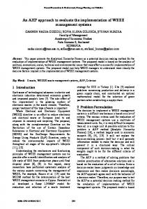
distance between the system and the designer is still considerable. 3 RESEARCH APPROACH The review of systems and relative knowledge representation methods has shown that main lacks in configuration are represented by data and knowledge formalization methods. Design for configuration stage requires a sequence of steps which can be resumed in: 1. Definition of an ordered set of configuration options; 2. Definition of a tree of alternative variant structures; 3. Definition of rules to map options to variants; 4. Association of geometries to each product variant. These steps are accomplished by the configuration designer gathering knowledge on the product in an unstructured manner and then transferring it in the tool by coding or pseudo-coding languages. Explicit information can be recognized in product structure which is represented by trees, or parts geometries in terms of CAD models. However, main part of knowledge is implicit, such as rules to map requirements to design choices, product assembling strategy or dimensioning constrains ad rules. It is implicit because information is unstructured, coded in the system and end user does not have access to it. 3.1 A Virtual Prototype based configuration framework In this section a framework is presented as a method to overcome problems linked to the traditional approach in product configuration. It is based on Configuration Virtual Prototypes (CVP), which represent classes of potential product instances. A CVP is an extended product definition which includes requirements, solutions, geometry as well as different types of design knowledge in a structured manner. Marketing requirements
Rules, standards, normative
Product Specification
Product Knowledge
Design choices
Configuration Virtual Prototype
Design for X rules, formulas, routines
Geometrical and topological data
Geometrical Data Product structure, parameters, assembly constraints Figure 1. Representation of the Configuration Virtual Prototype framework
Three main different design domains have been recognized as crucial in a CVP definition. As shown in figure 1, CVP is the product representation which makes product specification, geometrical data and product knowledge work together. The first aspect is related to sales requirements, in terms of product specification which lead to a particular product instance. Typically, specifications include product layout in terms of modules arrangement, marketing and functional requirements, required performances and design solutions choice. All these features are generally expressed by a set of parameters or options, whose availability is constrained by reciprocal conditions. The main outcome is represented by specific design choices and a required product structure. Modules choice and arrangement, as well as the detailed list of components are mainly drawn from these choices. The second aspect is related to product geometrical definition in terms of CAD models and technical documentation. As mentioned before, a product is here regarded as an assembly of configurable modules which embody the rules for geometrical configuration. Basically, products components and assemblies are the results of parametric models which are originally interactively defined by the designer. These models embody detailed geometric definition, as well as dimensioning parameters and strategies for building assemblies through mating constraints. Finally, knowledge management plays a significant role for the framework definition. While product specifications fix which parts are necessary and geometrical data how these parts are shaped and assembled, product knowledge contains the rules and constraints which set why functional requirements and details have been defined in a certain way. In the case of the design process of a new product variant or in a product redesign process, CVP definition updates through an acquisition process of new specifications, geometries and knowledge. Traditional problems connected to tools revision can be overcome if information exchange process between these different domains is maintained as automatic as possible. That means tools must be provided in order to import the three highlighted product information domains. Designer is required to input information using a semantic which is affine to its standard working environment. Such information is then automatically drawn inside the system and transformed in configuration tools usable formalisms. Designer inputs, formalisms and relative importing methods are briefly described as follows. Product Specification Domain The analysis of product development processes, in several companies, showed that the strategic choices related to new product lines are characterized, in the first phases, by the definition of Market Requirements (MRs) and Product Requirements (PRs). MRs are determined by marketing experts on the basis of customers analysis, PRs are the technical perspective of product concept. Their elaboration leads to the realization of the specific new solution. They have to be interrelated and structured through priority and dependence relations. Generally, the design knowledge which is useful in the first product development phases, especially the tacit knowledge, is rarely formalized. When it is schematically represented is classified by “flat” methods, without structured hierarchical relations and using only a level
4
Copyright © 2009 by ASME
of representation. In CVP approach, information is organized in two levels: the first one correlates the market requirements and product requirements; the second one translates them into functional requirements (FR). The knowledge formalization and elaboration tasks have been based on the Design Structure Matrix (DSM) methodology that uses matrices to represent interdependency relations between market requirements and product requirements [15]. DSM models have been also used as knowledge capture method in [16]. In such work, DSM is used as a roadmap of knowledge needed to populate a KBS as well as to link that system to other sources of knowledge outside its knowledge base.
Figure 2. Multi-level DSM for product specification management in CVP The DSM formalism allows reordering the information managed by “flat” models in order to easily have an order of priorities and dependence relations within the same level and between different levels. These are fundamental specifications to develop a suitable product configuration system. It has been observed that if MRs and PRs can be managed at the same level adopting an elaboration based on partitioning, tearing and banding algorithms. The functional specifications are reported at CVP level that is influenced and constrained by the choices established at higher level. The connection between the two levels it is based on rules dedicated to the specific applicative field. The DSM approach allows collecting marketing and technical information in an ordered structure that can be analyzed to reconfigure such information in a way suitable for a configuration software tool. The simplicity and immediacy of DSM representation is important since it allows experts to focus the attention on dependency relations between two parameters, neglecting the priority rules that generally are expression of the tacit design knowledge. The parameters are reported in the matrix in a casual order, then, the following partitioning and tearing operations redeploy them according to an order coherent with the dependency relations. Through banding algorithms, groups of design decisions that can be simultaneously performed are indentified. This implies the determination of the basic sequential steps for the configuration accomplishment. This ordered set of information is then stored by CVP model.
Product Knowledge Domain Product related knowledge for configuration purposes comprises different aspects. Here follows a list: 1. Mapping of Product or Marketing Requirements to Functional Requirements; 2. Mapping of Functional Requirements to specific Design Solutions; 3. Mapping of Design Solutions in product structures in term of parts and assemblies; 4. Dimensioning rules of parts and assemblies; 5. Multi level assembly building strategy to form final product model. CVP model explicitly embed this information using appropriate formalization techniques. As seen in the previous paragraph DSM has been recognized as a valid method to capture PR, MR and FR knowledge. Similarly, it is employed in mapping activities of points 2 and 3. The great advantage is given by the possibility of inputting complicate networks of design constrains and then resolve dependencies through DSM algorithms. The method provides an ordered set of choices or steps to be accomplished to solve the specific configuration task. Moreover, the method is useful to elaborate new procedures as contexts change. Point 4 refers to knowledge for part dimensioning. This is normally expressed in terms of formulas and if-then-else statements. Part of it can be recovered from parametric CAD model which are at the base of CVP. They embody the explicit definition of design parameters and some dimensioning rules which are more effectively input on CAD system rather than configuration tools. Finally, assembly strategy is traditionally based on procedures which position parts by coordinates in a completely unstructured manner. This approach requires onerous coding activity and moreover, a strong dependency of the solution to the specific product variant. In CVP such knowledge is recognized as implicitly stored in assembly template models, where the designer has already defined a strategy through a sequence of mating constraints. An algorithm is presented in the next paragraphs to elicit such knowledge and use it as source for product assemblies building strategy. Geometrical Data Domain The geometrical data domain will be discussed in detail in the following paragraphs of this paper. Here, points that were identified as crucial are listed: 1. The role of parametric template models as source of design solutions, product structure, parameters and assembly relations; 2. Simplified layouts as a powerful means to input and define product structure, desired solution and design parameters. 3. The development of a CAD independent product data structure which manages configuration tasks through standardized high level functionalities; In the following sections these aspects are described highlighting implementation details and obtainable
5
Copyright © 2009 by ASME
advantages. An example of the last point implementation is provided in section 4. 3.2 CVP design process On the base of the described framework, the CVP design approach is based on two stages. At first a CVP general base is realized based on the following steps: 1. Product modularity is identified and modules implementing solutions are standardized; 2. Market requirements and product requirements are listed and mapped to functional requirements; 3. Parametric CAD models are interactively prepared to represent main parts and assemblies of modules functional variants. Each model embeds a consistent parameters definition and stores non geometrical properties;
parts geometries, especially in the fields where configuration can be advantageous. Paying attention to the correctness of feature profile constrains and defining opportune guiding dimensions, designers are able to produce highly configurable parts. Such interactively defined models are referred as templates. Part templates come together in assembly templates, which embed positioning relations and further parameters. Configuration of assemblies is obtained replacing components with new correctly dimensioned ones, modifying parameters, number of repetitions and mating distances, writing non geometric properties and finally saving the model with a new name in a different folder.
4. A CVP IT support system imports modules data in terms of models structure, parameters and assemblies mating relations strategies; 5. Configuration knowledge is added in terms of design rules and formulas among parameters and product requirements; As second stage, a specific product instance is derived from the specialization of the base CVP model: 1. Specific Functional Requirements are drawn out MR and PR choices; 2. CVP support system elaborates a preliminary product layout which is refined by the designer through simplified geometrical entities; 3. CVP support system elaborates a definitive product structure and automatically generates part and assembly models. In the following section main functionalities required by this process are described. As part of a more extensive framework, object of a long term research, the following results are still not exhaustive but represent necessary portions of CVP proposed approach. 3.3 Extracting data from parametric template models An important way to bring configuration near to designer is based on a better use of modern features based CAD systems. These are powerful tools in creating parametric geometric models and nowadays consolidated in design departments. Instead of inputting data in configuration tools using specific semantics, designers feel more confident in using CADs. From modeling activity, information can be read about parameters, product structure and assembly constrains, automatically imported and employed for configuration purposes as explained as follows. In this work it is assumed that configured parts are obtained opening an interactively made model, modifying parameters, dimensions, number of repetitions, suppressing or reactivating features, writing non geometric properties as code, project number, description, etc…. and saving the model with a new name in a different folder. Thanks to advantages in parametric CAD systems, this approach covers a wide range of possible
Figure 3. An example of a flexible configuration task: dimensions are changed as well as components replaced with geometrical and topological similar ones. The realization of alternative design solution in terms of parts and assembly templates is familiar to designers who only need to verify the correctness of geometry adjustments in response to a clearly identified set of parameters. Such parameters must be automatically recognizable by the configuration system. To give a couple of examples, in SolidWorksTM (by Dassault System) parameters can be exposed through equations tool; in SolidEdgeTM (by Siemens) parameters can be recognized in the variable table just using recognizable names different from standard variables labels made of a “V” followed by some digits. Besides parameters, producing CAD models the user is defining a product structure in terms of part occurrences in assembly files. Again, there is no need to duplicate this information in configuration tools. It can be conveniently loaded through import functionalities. Finally, the designer interactively put mating relations between geometrical entities of models in order to build correct assembly files. He implicitly defines how parts must be conveniently assembled. Traditionally, in configuration tools, assemblies are built positioning parts using reference planes or locating them in the word coordinate system. This causes a loss of flexibility in changes represented by constraints between faces, edges and vertices. Intuitive and interactive constrain definitions are often transformed in complex formulas. In the following paragraph an approach for models automatic assembly out of standard templates relations is proposed.
6
Copyright © 2009 by ASME
3.4 Rebuilding assemblies mating relations out of templates Configured parts derive from the same models assembly templates are made of. So, they share the same topological structure and then corresponding geometrical entities can be somehow recognized. Again, this information can be read by the CVP in order to rebuild assemblies out of interactively created models. To this aim, CADs are usually provided of replacing functionalities. Entities ID’s or other naming strategies are employed to this end. However particular attention must be paid in case of well known entities persistent naming problems [17]. In fact substitution often fails as non trivial geometry similarities occur.
are changed through parameters updating (shaft, key) or because they are substituted with geometrically similar parts (the gear with the pulley).
Table 1. Data out of CAD models of a possible system under configuration Structure and Parameters Outer diameter, Inner diameter, Length, Shaft Key width, Key length Gear External diameter, Hole diameter, Width Key Width, Length, Thickness Mating relations Shaft-Key Planar mating with opposite normals Shaft-Key Planar mating with opposite normals Planar mating with opposite normals and Shaft-Key distance Shaft-Gear Concentricity Shaft-Gear Planar mating with opposite normals Key-Gear Planar mating with opposite normals Let consider a gear which is keyed on a shaft as in the figure 3. A parallel key is used to block the relative rotation of parts. Axial displacement is intentionally neglected. As first step designer produces parametric CAD models of the system. He creates three parts provided of dimensioning parameters: lengths, diameters, thickness, and so on. Then, he assembles the models adding mating relations between planar faces, coincidences of axes, etc… Table 1 reports an outlook on a possible mating strategy. Let now consider a different solution made of a smaller shaft, a key and a pulley instead of a gear. It represents a typical situation which can be faced in configuration systems. Dimensions are changed but also the template of the wheel, and then its geometry and topology. The substitution of the gear with a pulley cannot be automatically performed with standard CAD replacing functionalities but require a different approach. The proposed algorithm basically traverses the template structure and reads the list of relations, the couples of components being constrained and the geometric and topological entities (faces, edges or vertices) being mated. An analog structure is then instantiated in the new configured assembly. A specific data structure in the configuration tool manages the occurrences list and reproduces a set of analog relations between corresponding couples of components. Hence, main task is the identification of geometrical entities on configured parts which correspond to the ones being used in template files. This identification is necessary because parts
Figure 4. Geometric entities used in assembly mating relations. The entities identification approach is based on the following three considerations: 1. underling entity geometry must be the same, i.e. a planar face must be searched among planar faces, a straight edge among rectilinear edges. This condition must be always fulfilled; 2. planar faces normal or axis for cylindrical faces, i.e. element orientation must be equal. This condition is not always applicable: parameters could control the direction of tilted elements and then change such directions. Designer is just asked to model parts in a common coordinate system; 3. entities must show an high level of topology correspondence. For instance in the case of faces, it refers to the number and type of loops (inner, outer, etc…), the number of edges each loop is made of, the geometry of each edge of the loop, the angle formed by the face and each adjacent one. Once again, these conditions are not always applicable and depend on the particular component geometry. Such considerations have been used to identify a metric based on weights expressing the likelihood of correspondence. While the first condition cannot be derogated, each of the other two provides some score which are summed up to calculate the most probable entity to select. Algorithm implementation is then based on fuzzy logic and the following procedure: 1. Filter entities with required geometry type; 2. Assign a score of 100 if normal direction matches the required one, otherwise 0; 3. Assign a score from 0 to 100 to the level of topology similarity. Weight is equally split between loops, edges, adjacent faces geometry and angles. 4. Sum the scores and select the face with the higher one.
7
Copyright © 2009 by ASME
It may be noticed that orientation and topology have the same total weight. That means either orientation or topology can be decisive in the selection of the required entity. In the configuration context such approach has shown high reliability. Table 2 shows an example of orientation and topology considerations for the example in Figure 4.
Integrating this approach in CVP mainly impacts in O-O Structure instantiation phase. The process has been divided in the following sub-phases, as in figure 5: 1. Input from an user GUI of product main parameters concerning overall dimensions, constraints and interfaces;
Table 2. Geometrical and topological data of entities used in assembly relations in Figure 4
1a 1b 2a 2b 3a 3b 4a 4b 5a 5b 6a 6b
Geometry, topology and normal/axis direction 1 boundary loop of 4 linear and Plane circular edges, concave angles 1 boundary loop of 4 rectilinear Plane edges, convex angles 1 boundary loop of 4 rectilinear Plane edges, convex and concave angles 1 boundary loop of 4 rectilinear Plane edges, convex angles 1 boundary loop of 1 circular edge, Plane convex angles 1 boundary loop of 4 rectilinear Plane edges, convex angles Cylinder 2 loops of 4 linear, circular and (material spline edges each inside) Cylinder 1 boundary loop of 4 linear and (material circular edges outside) 1 boundary loop of 1 circular edge, Plane convex angles 1 boundary loop of many circular Plane and spline edges 1 boundary loop of 4 rectilinear Plane edges, convex angles 1 boundary loop of 4 rectilinear Plane edges, convex and concave angles
2. Automatic elaboration of a partial preliminary layout scheme, which satisfies previous requirements. The preliminary layout includes elements drawn from choices on GUI and bounds designer workspace.
Z
3. Modification and complete definition by the user of the components layout to fully represent the desired product structure.
-Z -Y
4. Automatic analysis of the layouts in order to extract information about type and dimensions of represented components;
Y X -X X X X -X Y -Y
3.5 Using simplified layouts to define product architecture The utilization of simplified layouts in product configuration expands typically rigid options of standard configuration systems. The objective is to use layouts to intuitively input product requirements which otherwise should be expressed by many parameters and choices on standard windows-based graphical user interfaces (GUI). For instance, a network of stiffeners welded over a sheet metal with different orientations, may be conveniently represented by lines segments. Otherwise, a huge number of variables expressing length, angle, and position for each of it must be defined. Moreover, CAD system itself can be employed as a powerful and intuitive environment to create layouts. The approach recalls the traditional way of sketching design solutions on paper. The second aim is to enlarge product family members obtained using the same base components. As long as parts represented as simplified geometry include knowledge to configure and adapt to product environment, many product alternatives can be obtained. This is a powerful method to overcome to traditional configuration system limitation, which mainly consists on a predefined set of solutions.
5. Instantiation of objects in the data structure representing parts being modeled in the layouts in a simplified manner. Coming to deep details, this approach extends the first part of the proposed configuration framework. User GUI is still used to provide product parameters, but in only main constraints, interfaces between modules, overall dimensions, etc… are input. This information is used to elaborate a preliminary layout bounding product workspace and fixing main constraints as axes, external interfaces, etc…. Information is supplied by simple entities such as points, axis, rectangles, boxes, cylinders, 3D sketches and construction surfaces represented in the parametric CAD environment. Such geometry is generated by specific routines embedded in the configuration tool. This preliminary layout acts as a constrained designing space where the user can manage details, add components represented by their skeleton geometry, define relative positions, represent product layout. Working on simple entities he can focus on functional and design aspects rather than secondary geometrical details.
Figure 5. Process of employing simplified layouts as a means for flexible product O-O structure instantiation
8
Copyright © 2009 by ASME
The configuration system will analyze the layouts, recognizing components from geometrical entity being employed, and reading dimensioning and positioning parameters. The correspondence between component geometries and their simplified representations is embedded in each component class definition. To this aim, product part objects store a double geometrical representation and the rules to define the detailed one out of the simplified one. For instance, let consider a shaft. A dotted segment can be used to represent its axis, length, position and orientation. Then, from a layout where some dotted lines are present, shaft objects are instantiated in the product structure and geometrical data drawn. Knowledge will provide dimensioning rules to compute other parameters such as diameters and the correct CAD template model will be individuated. Main aspect of this approach is the definition of a meaningful semantic to represent in a simplified manner complex shapes with elementary geometrical entities. No general rules are necessary since each component object internally defines the required simplified geometry. Two typical examples are set as follows: 1. Shafts and other components characterized by revolution geometries: these parts can be conveniently represented by their axis. Length of the axis represents the overall length of the component. 2. Stiffeners, plates, beams, supporting structures: these components are obtained from an extrusion of standard sections. Ends of component generally present additional features for fixing or adapting to adjacent parts. A segment network is sufficient to define complex structure as long as an attribute of each line (its color or line type) gives information about employed section. The configuration tool on the basis of predefined rules and relative orientation can resolve the interface between parts. 4
APPLICATION IN THE INDUSTRIAL CONTEXT
4.1 Gas turbine ducts design The research activity has been developed in collaboration with various Italian companies. The proposed approaches has been applied in the automation of design activities of a wide range of products such as air treatment units, lift structures, agricultural harvest machines, plastic molds, etc…. CAD system being employed range from SolidEdge (by Siemens) to SolidWorks and CATIA V5 (by Dassault System). Original applications have been developed using Microsoft Visual Basic or Microsoft C# languages. In this paper, gas turbine ducts have been chosen as the most representative and significant test case. In this case study the different aspects faced in section 3 have found a comprehensive application. In particular DSM approach has been used for functional requirements identification, product structure has been read from a CVP model, silencer panel assemblies have been rebuilt on the base of templates, duct inner insulation configured on the base of simplified layouts. The whole framework has not been implemented in a single supporting tool yet, but the various required functionalities explored with prototypal solutions.
The research was carried on in collaboration with V.G.F. srl and Tallarini srl, Italian supplier companies of General Electric. The context in which the research was developed required a high level of flexibility. The design of exhaust gas ducts involves competences from different field such as acoustic, fluid dynamics, structural, etc… So, from the very beginning an original framework has been proposed and developed as integration and collaborative environment. Commercial solutions were rejected for the lack of functionalities. In [18] details about the problem and first results were presented. In the following project development, the necessity of flexibility in parts definition and arrangement has led to a rewriting activity of the tool in order to approach the tasks and knowledge formalization in a more structured manner, based on the CVP model.
Figure 6. Part of hierarchical objects structure formalization. Note that ASM is for assembly and plural stands for object collections. The functional analysis of numerous plant typologies allowed identifying the nature of modularity of the systems. In particular a product platform has been determined and it has been represented in a product model structure. Such model contains all the information and rules useful for the detailed plant geometric configuration and for a selective and immediate data eliciting (geometric and non-geometric), used as input for the CVP. Finally, the classification of product variants allowed implementing suitable design choices procedures on the base of DSM approach results. It has been recognized that duct is an ordered set of modules called items along a 3D mean axis made of line segments. Each item is generally made of four walls. A wall is made of the structural part, the casing wall, and insulation. Casing wall consists on sheet metal panels, some stiffeners and parts to support insulation that are studs and scallop bars. On the other hand insulation is made of claddings, edge trims and batten channels which all are sheet metal parts that contain insulation fibers. Each part has been classified following an ObjectOriented approach and part of the resulting hierarchical structure is shown in Figure 6. Product analysis has led to fix
9
Copyright © 2009 by ASME
this structure as the most general representation of possible variants.
Figure 7. Representation of a possible implementation of the proposed configuration framework, the gas turbine ducts configuration tool structure The method described in Section 3 has been implemented in a prototypal configuration tool. In particular, a software package has been written using Microsoft Visual Basic .NET programming language to manage GUI and formalize duct objects structure and configuration rules. The system has been interfaced with a commercial 3D modeling kernel (SolidEdge by Siemens) and a relational database (Microsoft Access) where data on components are stored. The development process has followed the CVP model, even if the software architecture does not fully implement all its aspects, yet. In figure 7 a software structure is proposed. Users can interact with the system using a simple windows-based user interface and final results are represented by automatic configuration of detailed 3D CAD models, the automatic generation of technical documentation (2d drawings, bills of materials, costs account, etc…) and the definition of geometrical information for structural, acoustic and fluid dynamics analysis tools. In the context of the specific project, this tool was developed and customized to satisfy the specific partner needs. The core of the application is the O-O Structure and its Browsing Engine. Product is represented by linked objects forming a tree. Objects are instantiated from components classes. Common interface guaranties a uniform management of the structure across the product and among different products as shown in figure 8. The Browsing Engine traverses the objects structure generating geometries and documentation. This engine does not vary across different products and it does not require additional knowledge to work. In fact, all necessary data are
already stored or externally accessed by the objects structure. Objects functions are used to generate a complete list of parts without repetitions, assign unique codes, generate CAD models, write non-geometrical properties, etc…. Specific classes manage these operations in a CAD independent way (Figure 9).
Figure 8. UML representation of product models in CVP inheriting from standard interfaces
Figure 9. UML representation of CAD independent classes for the management of geometric models
10
Copyright © 2009 by ASME
4.2 Assembly template to rebuild mating relations In the configuration tool, a wide use of assemblies composed of parts templates has been made as mating relations knowledge source. In figure 10 an example is shown. It is related to a silencer panel framework rebuilding process. The algorithm implemented in the tool traverses the assembly template structure and imports component references and mating relations. Then, a new assembly is created finding corresponding occurrences in the O-O structure. Mating constrains are automatically created using the same typology of the ones in the assembly template. Entities to be mated are recognized using an algorithm based on the fuzzy logic approach described in paragraph 3.4. Assembly Template model
Figure 11. Examples of simple geometrical entities used to define panel insulation geometry. The method has shown good flexibility in insulation definition phase. It represents a trade-off between possibility to reach specific solutions and fast generation of the desired configuration. In fact adding or editing layouts details is very efficient due to the support given by the frame automatically generated by the configuration tool. Then system comes in short time to final 3D geometries.
Mating relations
Rebuilt assembly with configured parts Figure 10. Usage of templates as knowledge source for silencer panel assembly mating relations rebuilding 4.3 Using simplified layouts to define product architecture Simplified layouts have been successfully employed reaching high level of flexibility in insulation definition. Figure 11 shows strategies in use for a simplified representation of parts. Studs are characterized by revolution geometry and are welded on panels. Then, only points are necessary for their position: circle centers will represent those points. Scallop bars are represented by segments, which combined with stud circles, provide all necessary geometrical parameters. Claddings are represented by closed paths passing through stud centers. An offset operation during generation will add extra surface to reach necessary extension. The developed tool automatically provides an insulation layout on the basis of input dimensions in terms of wall extension and a possible component arrangement. This layout is obtained from rules stored in the system. Then the user can modify and complete the layouts, customizing the solution to the specific needs. Each insulation component type is drawn in a specific SolidEdge sketch feature. Then, the system reads the various CAD sketches extracting the information for the instantiation and generation of the parts and the subassemblies. Finally, components are assembled to their final configuration as in figure 12.
Figure 12. Example of item generation result. Insulation components in their final arrangement on the base of respective simplified layout 5 CONCLUSIONS In the last decades, configuration tools have appeared in the academia first, and then on the market with scarce results. The initial target on variants configuration has moved on redesign activities and the necessity to support the evolution of products, the incorporation of new features, functionalities and solutions. Traditional tools approach is not still adequate. This paper has presented a framework to manage configuration in a flexible way in order to cope with redesign activities. The notion of Configuration Virtual Prototype has been introduced as a way to store information on a new product class taking into account three main domains: specifications, geometrical data and design knowledge. CVP gathers data from the designer activity and comes to a formalization, which can be employed for configuration
11
Copyright © 2009 by ASME
purposes. In particular Design Structure Method is used to translate product and marketing requirements in an ordered set of functional ones. Parametric CAD models of template product instances are used as source of geometrical solutions, design parameters and mating constrains between parts. Finally, simplified layouts are used as source of original design solutions and parts arrangement in order to provide flexibility and widen solution space. Methodology proposed in this work partially covers aspects required by the whole framework. The detailed description of algorithms and relative tools is the objective of a long-term research. However, prototypal implementations have shown the feasibility of some recurrent issues, as shown in the test case section. The research activities now should focus on tools for a more explicit formalization of knowledge in CVP based systems.
applications development”, Proceedings of ASMEDETC'00, Proceedings CD-ROM. [10] Colombo, G. Cugini, U. and Mandorli, F., 1992, “An Example of Knowledge Representation in Mechanical Design Using Object-Oriented Methodology”, Proceedings of The 1992 European Symposium Simulation and AI in Computer-Aided Techniques, pp. 208-214. [11] Colombo, G., Girotti, A. and Rovida, E., 2005, “Automatic design of a press brake for sheet metal bending”, Procedings of ICED 05, pp. 124-125. [12] Mandorli, F., Rizzi, C., Susca, L. and Cugini, U. , 2001, “How to Implement Feature-Based Applications using KBE Technology”, International IFIP Conference on Feature Modeling and Advanced Design-For-The-LifeCycle Systems FEATS 2001, Proceedings CD-ROM.
REFERENCES [1] Simpson, T., 2003, “Product platform design optimization: status and promise”, Proceedings of ASME DETC 2003, Chicago.
[13] Germani, M. and Mandorli, F., 2004, “Self-configuring components approach to product variant development”, AIEDAM Special Issue: Platform Product Development for Mass Customization, Vol. 18(1), pp. 41-54.
[2] Attaluri, V., McAdams, D., Stone, R. and De Crescenzo, A., 2006, “Visual representations as an aid to concept generation”, Proceedings of the 2006 ASME Design Engineering Technical Conferences & Computers and Information in Engineering Conference, Philadelphia, Pennsylvania.
[14] Bermell-Garcìa, P., Fan, I.-S., Li, G., Porter, R. and Butter, D., 2001, “Effective abstraction of engineering knowledge for KBE implementation”, Proceedings of ICED 01, Vol. 1, pp. 99-106.
[3] Lombeyda, S. and Regli, W., 1999, “Conceptual design for mechatronic assemblies”, Proceedings of the fifth ACM symposium on Solid modeling and applications.
[15] Germani, M., Mengoni M. and Raffaeli, R., 2006, “Design Structure Matrix used as Knowledge Capture Method for Product Configuration”, Proceedings of the 9th International Design Conference - DESIGN 2006, Edited by D. Marjanovic, Vol. 1, pp. 253-262.
[4] Susca, L., Mandorli, F. and Rizzi, C. , 2002, “How to represent "Intelligent" components in a Product Model: a Practical Example”, Knowledge Intensive CAD to Knowledge Intensive Engineering, Edited by U. Cugini, M. Wozny, Kluwer Academic Publisher , pp. 159 – 172.
[16] Whitney, D. E., Dong, Q., Judson, J. and Mascoli, G., 1999, “Introducing Knowledge-Based Engineering” Interconnected Product Development Process, M.I.T. Center for Innovation in Product Development, Cambridge, MA.
[5] Tiihonen, J., Lehtonen, T., Soininen, T., Pulkkinen, A., Sulonen, R. and Riitahuhta, A., “Modeling Configurable Product Families”, Proceedings of ICED 99, Vol. 2, pp. 1139-1142.
[17] Kripac, J., 1995, “A mechanism for persistently naming topological entities in history-based parametric solid models”, Proceedings of Solid Modeling ’95 – Third Symposium on Solid Modeling and Applications, Ed. Hoffman, C.M. and Rossignac, J.R., ACM Press, Sal Lake City, UT, USA, Vol. 1, pp. 21-30. Also in: Computer- Aided Design, Vol. 29(2), pp. 113-122.
[6] Mandorli, F., Berti, S. and Germani, M., 2002, “A KBE system to manage the module configuration using the corporate knowledge”, Proceedings of DESIGN 2002, Vol. 1, pp. 385-390. [7] Sabin, D. and Weigel, R., 1998, “Product Configuration Frameworks – A Survey”, IEEE Intelligent Systems and Their Applications, Vol. 13(4), pp. 42-49. [8] Capozzi, T. J., 2005, “Impact of the evolution of RuleDriven Design”, Proceedings of ASME Power Conference.
[18] Germani M., Raffaeli, R., Bonaventura, L. and Mandorli, F., 2005, “Development of a Collaborative Product Development Tool for Plants Design”, Proceedings of the 15th International Conference in Engineering Design - ICED 2005: Engineering Design in the Global Economy, Editor: Andrew Samuel and William Lewis, Proceedings CD-ROM, Malbourne.
[9] Mandorli, F. and Bordegoni, M., 2000, “Product model definition support for knowledge aided engineering
12
Copyright © 2009 by ASME