An Approach to the Pervasive Formal Specification and Verification of an Automotive System Status Report Tom In der Rieden∗
Steffen Knapp
Dept. of Computer Science Saarland University P.O. Box 151150 66041 Saarbrucken ¨ Germany
Dept. of Computer Science Saarland University P.O. Box 151150 66041 Saarbrucken ¨ Germany
[email protected]
[email protected]
ABSTRACT The Verisoft project aims at the pervasive formal verification of entire computer systems. In particular, the verification of functional and timing properties of the Automotive System is attempted. This is a distributed system, whose components consist of hardware (processor and devices), a real-time operating system, and applications. In this paper we give an overview of the system architecture and its industrial relevance. We will discuss in detail the model layers from the hardware up to a computational model for concurrent user processes interacting with a generic microkernel written in C. This is work in progress, so we will report on its current status, our goals and the next steps we want to take.
Categories and Subject Descriptors C.4 [Computer Systems Organization]: Performance of Systems—Modeling techniques; Reliability, availability, and serviceability
General Terms Design, Reliability, Verification
1.
INTRODUCTION
Back in the days, a car merely consisted of pure mechanical parts. Electronic components could only be found in a very few spots and their complexity could be handled by an average mechanic. Times have changed since then. The customer’s desire for more luxury options, the need to decrease ∗ Work partially funded by the German Federal Ministry of Education and Research (bmb+f) in the framework of the Verisoft project under grant 01 IS C38.
Permission to make digital or hard copies of all or part of this work for personal or classroom use is granted without fee provided that copies are not made or distributed for profit or commercial advantage and that copies bear this notice and the full citation on the first page. To copy otherwise, to republish, to post on servers or to redistribute to lists, requires prior specific permission and/or a fee. FMICS’05, September 5–6, 2005, Lisbon, Portugal. Copyright 2005 ACM 1-59593-148-1/05/0009 ...$5.00.
fuel consumption going hand in hand with the need to decrease pollutant emissions have led to an increasing number of electronic devices even in a middle-class car. The sheer complexity of these systems has reduced the coverage of tests to a minimum and made this technology unfeasible even for current designs. We think that the formal specification and verification of complex systems is the only way out of this dilemma. In cooperation with BMW Group AG we have decided to develop and verify an implementation of the eCall Emergency Call as proposed by the EU Commission [8, 27] in the Verisoft project [26]. We have modeled the scenario as a distributed system in AutoFOCUS [28] and Isabelle/HOL [18] and are going to show its functional and timing correctness. In order to achieve a maximal pervasiveness and by this to minimize the chance for an undiscovered error, we have developed a model stack from the hardware gate level up to the state transition diagrams in AutoFOCUS. The correctness of the system will be shown by simulation theorems between adjacent layers. This project is work in progress and by far not complete. Nevertheless, in this writing we will give a detailed system description with the underlying standards and specifications from automotive industry (Sect. 3.2). In Sect. 4 we give an introduction into the lower half of our model stack. In detail, we will discuss models for assembler programs and C programs (Sect. 4.1 and Sect. 4.2) before we introduce a new computational model for user tasks interacting with a microkernel (Sect. 4.3). In Sect. 4.5 we outline a OSEKtime Operating System like concrete implementation of a micro kernel.
2.
MOTIVATION
The introduction of the CAN-Bus by Bosch for massproduction in the early nineties initiated the rapid growth of the electronic share in cars [11]. In 2000, about 20 percent of a car was electronic components. According to Merker Management Consulting, this share will grow to 35 percent in 2010. The situation is even worse, since most control units will communicate and interact with each other. For example, the electronic system of the recent BMW 7 series (E65) consists of five bus systems, which interconnect 45 to 75 electronic control units (ECUs) and transport about 2500 signals. Nevertheless, about 90 percent of all innova-
tions in cars are direct or indirect results of new software and electronic components. The market volume for automotive software is expected to rise from 25 billion Euros in 2000 to 100 billion Euros in 2010. Since one modern control unit already consists of software and hardware, their combination into highly interactive and dependent distributed systems leads to even greater complexity and bigger difficulty in design and integration. Latest statistics show, that in 1998 45.2 percent of all breakdowns were due to electrical and electronic problems. This number rose to 49.6 percent in 2001 and is still increasing [6]. About 80 percent of these failures are due to software problems. There are multiple reasons: • Specifications are ambiguous, insufficient, or wrong (or all together). • Constructions and implementations do not meet specifications. • Components are manufactured by different suppliers and do not interact correctly. Unfortunately, most of the occurring errors do not come up systematically, but only from time to time under a priori unknown and non-reproducible circumstances. Due to the sheer amount of cases, testing is often restricted to a very small subset. So the chance of a design or implementation error to stay undisclosed until the mass-production of a certain car model is very high. Unlike with computers people are not willing to accept erroneous cars. Automobile companies do not only lose hundreds of millions for call-backs, but also lose the trust of their precious customers. This is especially the case for luxury class car manufacturers. Things can become even worse, as soon as safety critical systems are concerned. Since these systems do not only rely on correct functionality but have also real-time constraints, the design again becomes more complex to handle. The consequences of safety critical systems failures are usually dramatic. Wrongful death and personal injuries caused by such failures may cost car manufacturers not only reputation, but also money if they are found liable.
3.
SYSTEM DESCRIPTION
3.1
eCall
eCall is a proposal of the EU’s eSafety group started in December 2004. eSafety is a joint initiative of the European Commission (DG Enterprise and DG Information Society), industry and other stakeholders and aims at accelerating the development, deployment, and use of Intelligent Integrated Safety Systems that use information and communication technologies in intelligent solutions in order to increase road safety and reduce the number of accidents on European roads [7]. In the case of an accident, an automatic call to a public safety answering point (PSAP) is initiated via a mobile phone network and by using the Europe-wide E-112 emergency call. Then, a message is transmitted to the PSAP operator containing
• a vehicle identification, • a qualifier giving the severity of the incident, and • the identification of the service provider. Furthermore, the emergency call can be enabled manually by the driver in case of a less severe incident. The EU commission is planning to make the installment of a built-in eCall system compulsory for all new cars as from 2009. There are several benefits expected from the Europe-wide introduction of eCall: • The response time to the accident is reduced by up to 50 percent. • A reduction of accident severity in 15 percent of all cases. • 2,000 lives saved annually. • Cost reduction of about 21 billion Euros in EU15 annually.
3.2
System Architecture
For our exemplary implementation of eCall, we have set up a scenario of independent electronic control units, which are interconnected via a FlexRay bus [9]. All ECUs share the same general layout: based on a hardware platform as described in Sect. 3.3, we run a real-time operating system like the one described in the OSEKtime Operating System Standard [21]. Further details will be discussed in Sect. 3.4. The topmost layer is built by the application software and the FlexRay driver. We have split our implementation into four independent parts: mobile phone, navigation system, crash sensor and the emergency call implementation. Each application runs on an ECU of its own. For more details see Sect. 3.5.
3.3
The Hardware Layer
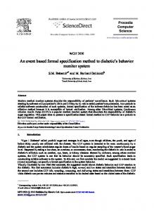
Within an ECU we choose a hardware layout (referred to as a node) which is based on a common hardware design. On the one hand this helps minimizing the production costs. On the other hand only one design – up to the application layer – has to be verified. The design includes a central processing unit (CPU), random access memory (RAM), a timer and a FlexRay communication controller (see Fig. 1).
App
App
OSEKtime
FlexRay
FTCom
VAMP
Controller
FlexRay Bus
• the time of the incident, • exact location including direction of driving,
Figure 1: Single Node Details
Real-time operating systems are relying on tightly synchronized clocks. In order to circumvent single points of failure (SPF) each node has its own local clock. This requires a clock synchronization mechanism, which will be provided by FlexRay. The CPU serves as the hub within a node. In our scenario, we use the VAMP (Verified Architecture Microprocessor) [5] architecture, which includes a memory interface for the RAM. The VAMP architecture is described in the subsequent section in more detail. External devices like the crash sensors or the mobile phone as well as the timer and the FlexRay controller communicate with the CPU through common I/O interfaces. Moreover the timer supplies the FlexRay communication controller with a notion of time. The FlexRay controller serves two purposes. First it manages the inter-node communication via the FlexRay bus. Second it is responsible for cyclically supplying the timer with a correction quantum which ensures the synchronization of the clocks. The mechanism for doing so as well as the architecture of the FlexRay communication controller are described in Sect. 3.3.2.
3.3.1
Central Processing Unit (CPU)
The VAMP is a pipelined 32-bit RISC CPU with caches and a full DLX instruction set [12, 16] including extensions for single and double precision IEEE754 floating-point operations, resulting in about 100 instructions. It supports nested precise (and partially maskable) interrupts and makes use of the Tomasulo Out-of-Order execution scheme. The VAMP was developed at our institute in the years 1999 to 2003. The design has been synthesized on an FPGA and makes up for about 1,500,000 gates. The VAMP has been fully formally verified using the interactive theorem prover PVS [5, 22]. We are currently working on an I/O extension for the VAMP, which allows us to connect external devices, e.g. the FlexRay controller, to the processor.
3.3.2
Only one node can send per slot, whereas empty slots are permitted, too. A message is of the form (msgid, msgval) where msgid denotes a unique message id (also called message type) and msgval gives the corresponding value. There is a bijective mapping from slots to message types (note that we omit empty slots here). CPU
Send Buffer
FlexRay Slot
Bus Interface
FlexRay Bus
Figure 3: FlexRay Controller Details All nodes need about synchronous clocks. Since quartzes used in nodes are not precise enough, these clocks have to be synchronized periodically. To deal with this matter, during startup phase, all nodes agree on certain messages to be sync messages. These messages are used to find out the local clock drift by comparing the expected time of arrival for that given message to its actual time of arrival (see Fig. 4). There is a special phase at the end of one FlexRay round, called network idle time (NIT). This time share is used by all nodes to correct their local clocks. Difference = Correction Value Message FlexRay Slot
Expected Arrival Time
FlexRay Round
Time
Figure 2: FlexRay Timing
Receive Buffer
Timer
FlexRay
FlexRay is a communication system that will support the needs of future in-car control applications. At the core of the FlexRay system is the FlexRay communication protocol. The protocol provides flexibility and determinism by combining scalable static and dynamic message transmission, incorporating the advantages of familiar synchronous and asynchronous protocols [9]. Bus arbitration is based on rounds. This gives us cyclical behavior and therefore deterministic message delays which are crucial for real-time critical applications. One round consists of several statically defined time slices, the so called slots. In our scenario, all slots are of the same length. The distribution of slots is equal in each round. The typical length of one round is about 10 ms at a data rate of 10 Mbit/s.
I/O Controller
Actual Arrival Time
Time
Figure 4: Clock Correction The FlexRay controller manages the interaction with the CPU. Two hardware buffers are used to store the data sent or received via the FlexRay bus. Each buffer is capable of storing a single message. With the help of timing information provided by the timer and a static table (i.e. the bijection mentioned above) the bus interface either decodes received messages or encodes messages in order to send them over the FlexRay bus. In addition, the bus interface is responsible for the synchronization of the timer.
3.4
OSEKtime Layer
OSEK/VDX is an open operating system standard of the European automotive industry. More than 50 major companies belong to the Technical Committee Partners, e.g. Volkswagen AG, BMW AG, Adam Opel AG, Daimler Chrysler AG. OSEK is an abbreviation for “Offene Systeme und deren Schnittstellen f¨ ur die Elektronik im Kraftfahrzeug”, which translates to “Open Systems and the Corresponding Interfaces for Automotive Electronics” [21].
OSEKtime is a specification for a time-triggered operating system with a fault-tolerant communication layer as a standardized run-time environment for highly dependable real-time software in automotive electronic control units. The OSEKtime operating system supports static scheduling and offers all basic services for real-time applications, i.e., interrupt handling, dispatching, system time and clock synchronization, local message handling, and error detection mechanisms. It is an extension to the OSEK/VDX standard. OSEKtime implements the following properties: • predictability, i.e. the deterministic and a priori known behavior even under peak load and fault conditions. • fault tolerance, i.e. versus communication faults. Since these properties imply static fixed time scheduling, we have to provide worst case execution times for all applications and for all operating system routines. Task execution in OSEKtime is controlled by a real-time scheduler and a dispatcher table. The scheduler activates the tasks sequentially corresponding to the entries in the dispatcher table. One entry in the dispatcher table consists of the task id, the start time for the task and its maximal runtime (deadline). One full execution of the whole dispatcher table is called one dispatcher round. Since we use the underlying FlexRay protocol to synchronize the clocks and to ensure proper cooperation in between FlexRay and OSEKtime, we demand that the dispatcher round length is a multiple of the FlexRay round length. Additionally, there is a privileged idle task. This task is not listed in the dispatcher table and has neither start time nor deadline. Whenever there is unused time in one dispatcher round, the idle task will be dispatched. The OSEKtime standard comprises a fault-tolerant communication layer, FTCom, which supports real-time bus protocols as FlexRay. FTCom offers the following services: • Global Message Handling (including replication and agreement) • Time service and optional external clock synchronization FTCom is divided into four layers: • the application layer, which provides an application programming interface (API), • an optional message filtering layer, which will not be considered in our model, • the fault tolerant layer, and • the interaction layer, which provides the services for the transfer of messages via network. Communication between FTCom and FlexRay is organized via a shared memory region inside FTCom, the so-called ttFT CNI. All messages received via the FlexRay bus are stored in this memory region. Messages sent by local applications are stored in the ttFT CNI and then delivered by FlexRay to all other nodes. Optionally, all messages can be sent redundantly. The content of ttFT CNI is then defined by the results of an agreement algorithm (RDA - replica determinate algorithm). We will not make use of any replication algorithm in our scenario.
eCall Appl.
Mobile Phone
Navigation
Sensors
Node 1
Node 2
Node 3
Node 4
Figure 5: System Structure
3.5
Application Layer
At a top level, we have distributed our implementation of eCall to four independent applications. Each application runs on an ECU of its own. The communication between two or more applications is realized via the FTCom layer and the FlexRay bus. The eCall application collects all relevant data and, if necessary, initializes the emergency call. The navigation application sends periodically the current position of the car (e.g. in GPS format). The coordinates will be stored by the emergency call application. Such a design is more stable compared to an emergency call application polling the data from the navigation module in case of a crash, after which the navigation system might have failed. The crash sensor sends cyclically the current crash status of the car. With this parameter, the emergency call application can decide, if an emergency call has to be placed or not. The mobile phone device provides functions to initialize a call, send data via the mobile network or close a connection. The eCall application uses these functions to place the actual emergency call.
4.
MODELING
We are going to model in a bottom-up manner. The lowest level in the model is built by the logical gates of the VAMP processor. We will then provide a layer of assembler machines, called physical machines. This model represents an assembler programmer’s view on the hardware (see Sect. 4.1). Note that we have chosen the term physical to denote that we do not use address translation or other virtual memory features but operate on a pure physical memory. Furthermore, we will introduce a new model called communicating virtual machines (CVM) in which concurrent user processes interact with a generic microkernel. The user tasks and the generic microkernel are written in a subset of C called C0. We will introduce a formal model of C0 machines which represents these C0 programs. In order to achieve pervasiveness in our model, we also talk about the correctness of the compiler translating C0 programs to assembler in Sect. 4.2. Beneath the usual C functions, the microkernel in Sect. 4.3 can call a special set of functions called CVM primitives which alter the state of user processes, e.g. copy data between them. The linking of the generic micro kernel to the implementations of the CVM primitives leads to the concrete kernel. Necessarily, this implementation needs to have assembler portions due to the fact that e.g. processor registers are not visible in the variables of a C program. Therefore we will extend our C0 semantics in order to deal with these assembler portions.
In Sect. 4.5 we will show how we instantiate the generic microkernel from Sect. 4.3 with an OSEKtime-like implementation. We will introduce the specific system calls and tasks that are needed to handle the special demands regarding communication between tasks and nodes.
4.2.1 C0 Semantics
COF
CVM
Instantiation
DLX−ASM
DLXSpec
CVM2DLX
V−DLX
Abstraction
Figure 6: Model Stack
4.1
Physical Machines
We have described shortly the VAMP processor we use in Sect. 3.3. Physical machines describe a processor operating (in our scenario) on physical memory.
4.1.1
Notation
We denote bit vectors by a ∈ {0, 1}n . Bit j of bit vector a is denoted by a[j]. The concatenation of bit vectors a ∈ {0, 1}n and b ∈ {0, 1}m is denoted by a ◦ b ∈ {0, 1}m+n .
4.1.2
Configuration
A configuration cP of a physical machine has the following components: • cP .R ∈ {0, 1}32 for a variety of processor registers R. We consider here a pipelined architecture with a delayed branch mechanism which is implemented by two program counters, cP .DP C ∈ {0, 1}32 and cP .P CP ∈ {0, 1}32 . 32
• A byte addressable memory cP .m : {0, 1}
8
→ {0, 1} .
Computation on the physical machine is modeled by the function δP that computes a successor configuration c0P for a given configuration cP . The next state function δP is defined by the semantics of the instruction set. The physical machine reads from the memory to fetch instructions and to execute load instructions, it writes to the memory to execute store instructions.
4.2
industrial usage. Therefore we came up with several restrictions (see next section) on C which lead to simple P ascal like semantics. This subset of C we called C0. In this section, we will sketch the formal semantics of C0 and state the correctness theorem of a C0 compiler. Finally, we will extend the C0 semantics to in-line assembler code.
Semantics, C0A Semantics and Compilation C0
Since we want to consider several programs (like FlexRay driver and applications) running under an operating system, the computations of these programs are interleaved. Therefore, our compiler correctness statement is based on a small steps operational semantics. The programming language C “in its full beauty” has rather complex semantics allowing an error prone programming style. Although the semantics of Pascal can be written down in a few pages, we decided not to use this language. This is due to the fact that C is the first choice in programming languages when it comes to
In C0 types are elementary (bool, int, . . .), pointer types, or aggregates (array or struct). A type is called simple, if it is elementary or pointer type. We require that all types including pointer types have to be fixed at compile-time. We define the abstract size of types for simple types t by size(t) = 1, for arrays by size(t[n]) = n · size(t) P and for structures by size(struct{n1 : t1 , . . . , ns : ts }) = i size(ti ). Values of variables of simple types are called simple values. Variables of aggregate types have aggregate values which are represented as a flat sequence of simple values. Variable names and literals are expressions (e). So are array and struct accesses (e[index], e.name), dereferencing (∗e) and “address-of” operations (&e). Expressions in C0 do not have side-effects, therefore pointer arithmetic is forbidden as well as function calls as part of an expression. For expressions e and ei we can define statements (denoted as s or s0 ) as (i) memory allocation e = new type, (ii) while loops while e do s, (iii) assignments e = e0 , (iv) if conditionals if e do s else s0 , (v) function returns return e, (vi) empty statement skip, (vii) sequential composition (s; s0 ) (viii) and last but not least function calls e = f (e1 , . . . , en ). We require function bodies to contain only a single return statement exactly at the end. All restrictions, which we have introduced, seem to comply with the MISRA guidelines [19] for the use of the C language in critical systems. C0 Configuration. A C0 configuration cC0 has the following components: 1. The program rest cC0 .pr. This is a sequence of C0 statements that is still to be executed. 2. The type table cC0 .tt collects information about types used in the program. 3. The function table cC0 .f t contains information about the functions of a program. It maps function names f to pairs cC0 .f t(f ) = (cC0 .f t(f ).ty, cC0 .f t(f ).body) where cC0 .f t(f ).ty specifies the local variables, the types of the arguments and the return value of the function, whereas CC0 .f t(f ).body specifies the function body. 4. The recursion depth cC0 .rd. 5. The local memory stack cC0 .lms. It maps numbers i ≤ cC0 .rd to memory frames. The global memory is cC0 .lms(0). We denote the top local memory frame of a configuration cC0 by top(cC0 ) = cC0 .lms(cC0 .rd). 6. A heap memory cC0 .hm. We simplify a memory frame to a mapping of variable names to values in this context, since the full definition is out of scope for this writing. Due to space restrictions, we cannot give the definition of the transition function δC0 mapping C0 configurations
cC0 to their successor configurations c0C0 = δC0 (cC0 ). As an example, we give the partial definition of the function call semantics. Assume the program rest in configuration cC0 begins with a call of function f with parameters e1 , . . . , en assigning the function’s result to variable v, formally cC0 .pr = f call(f, v, e1 , . . . , en ); r. In the new program rest, the call statement is replaced by the body of the function f taken from the function table. c0C0 .pr = cC0 .f t(f ).body; r and the recursion depth is incremented by one: c0C0 .rd = cC0 .rd + 1 and a new memory frame for the local variables of the function will be initialized.
4.2.2
Compiler Correctness
Compiler correctness is based on a simulation relation between C0- and physical machines: consis(aba)(cC0 , cP ). The relation takes a function aba as a parameter which maps sub variables S of the C0 machine to their allocated base addresses aba(cC0 , S) in the physical machine. The function may change during computation (i) if the local memory changes due to function calls and returns or (ii) if reachable variables are moved on the heap during garbage collection (not implemented yet). Essentially, the simulation relation consists of four conditions: 1. Value consistency v − consis(aba)(cC0 , cP ) states that reachable elementary sub variables x have the same value in the C0 machine and in the physical machine. 2. Pointer consistency p − consis(aba)(cC0 , cP ) requires for reachable pointer variables p, which point to a sub variable y, that the value stored at the allocated address of variable p in the physical machine is the allocated base address of y. This induces a subgraph isomorphism between the reachable portions of the abstract heap in the C0 and the concrete heap in the physical machine. 3. Control consistency c − consis(cC0 , cP ) states that the delayed PC of the physical machine used to fetch instructions points to the start of the translated code of the program rest cC0 .pr of the C0 machine. 4. Code consistency code − consis(cC0 , cP ) requires that the compiled code of the C0 program is stored in the physical machine cP beginning at the code start address cstart (note that this implies the forbiddance of self-modifying code). The simulation theorem claims that for all C0 machine computations (c0C0 , c1C0 , . . .) there is a computation (c0P , c1P , . . .) of the physical machine, step numbers (s(0), s(1), . . .) and a sequence of allocation functions (aba0 , aba1 , . . .) such that for all steps i and S = s(i) we have consis(abai )(ciC0 , cS P ). For further details see [14].
4.2.3
In-line Assembler Code
As pointed out in Sect. 4.3, operating system kernels necessarily contain assembler code. So we have to extend the C0 language by a statement of the form asm(u), where u denotes a sequence of assembler instructions. We call the resulting language C0A . We put certain restrictions on the use of in-line assembler code: (i) we reduce the available instruction set (e.g. no load/store of bytes and halfwords,
relative jumps only), (ii) target addresses of store word instructions must be outside the code and data region of the C0A program or they must be an allocated base address of the C0A program of type int or unsigned int, (iii) the last instruction in u must not be a jump or a branch instruction, (iv) the execution of u must terminate, (v) jump and branch targets must be inside of u, (vi) execution of u must not produce misalignment or illegal interrupts. In-line assembler parts can modify parts of the physical machine configurations which are not visible for C0, e.g. the processor registers. Thus the next state function δC0A needs an additional parameter, a physical machine. To express the meaning of assembler code changing the values of C0 variables, we parametrize δC0A – like the consis relation – with an allocated base address function aba. As long as there is no in-line assembler code executed, we ignore the second input parameter and set the second output parameter to an arbitrary but fixed physical machine configuration x: δC0A (aba)(ciC0 , ciP ) = (δC0 (ciC0 ), x). The execution of in-line assembler code makes the definition of the transition function harder and goes beyond the scope of this paper. In brief, we construct a corresponding sequence of C0 computations for the sequence of physical machine computations representing the execution of the in-line assembler part. If an assembler instruction changes the value of some C0 variable, we reflect this change in the corresponding C0 configuration, otherwise the C0 configuration stays unchanged.
4.3
CVM
Communicating Virtual Machines (CVM) are a computational model for a generic abstract microkernel interacting with a fixed number of user processes. From a kernel implementor’s point of view, CVM encapsulates the low-level functionality of a microkernel and provides access to it as a library of functions, the so-called CVM primitives [10]. Although the CVM model has been developed to support virtual machines, we will only use physical machines as mentioned above.
4.3.1
Configuration
A CVM configuration ccvm has the following components: • User process physical machines represented by configurations ccvm .up(u) for user process indices u ∈ {1, . . . , P } and fixed P as introduced in Sect. 4.1 • A C0 machine configuration ccvm .ca of the so-called abstract kernel as seen in Sect. 4.2. This machine must (i) have a function kdispatch, and (ii) declare certain functions called CVM primitives, with an empty body, arguments and effects as described below. • The component ccvm .cp denotes the current process: ccvm .cp = 0 means that the kernel is running, while ccvm .cp = u > 0 means that user process u is running. A computation of the CVM machine is parametrized over a list of external interrupt events eevs, one event mask eev e with e signals for each user process step (the running kernel cannot be interrupted). These external interrupt events are, for example, used to efficiently interact with I/O devices, e.g. a hard disk or a network card. A mathematical model of a hard disk and a paper and pencil proof for a low level device driver can be found in [13].
4.3.2
Computation
In this section we define the next state function δcvm of the CVM model. It maps the external events list eevs and a CVM configuration ccvm to its successor configurations c0cvm and the new external events list eevs0 , so δcvm (eevs, ccvm ) = (c0cvm , eevs0 ). The next state function of the CVM model distinguishes two basic cases: (i) If ccvm .cp 6= 0, i.e. the current process is not the kernel, we have a user computation. (ii) Otherwise, we have a kernel computation. In the first case, we check if there is an interrupt, either internally or with respect to the external events eevs. If no interrupt has occurred, the next CVM step is just a step of the corresponding physical machine, i.e. c0cvm .up(u) = δv (ccvm .cp(u)). If there is an interrupt, we start the execution of the abstract kernel. kdispatch denotes the function for the kernel entry point, which we will call with the exception cause and data. Furthermore, we set the current process ccvm .cp to 0 and the kernel’s program rest ccvm .ca.pr to the function call for kdispatch. Kernel computations start with the call of the function kdispatch as shown above. There are now two possibilities of how to go on: (i) The kernel’s program rest does not start with a call of a CVM primitive. Then we do a regular C0 semantics step: c0cvm .ca = δC0 (ccvm .ca) (ii) Otherwise, the corresponding CVM primitive is called. All kernel computations have to end with the call of the CVM primitive start, which hands control over to a specified user process. With this, the kernel stops execution and is restarted again on the next interrupt. Due to restrictions of space we will only describe a few selected primitives. We ignore any preconditions and corner cases which are straightforward to specify and resolve. • The CVM primitive start, taking one argument, hands control over to the given user process. For ccvm .ca.pr = f call(start, v, e1 ); r and u = va(ccvm .ca, e1), where va(ccvm .ca, e1 ) defines the value of variable e1 in the abstract kernel, we set c0cvm .cp = u. With this definition the kernel stops execution and is restarted again on the next interrupt. • The CVM primitive get vm gpr reads register GP R[r] of process u. We define get vm gpr(r, u, ccvm .up) = (ccvm .up(u).GP R[r], ccvm .up). • The CVM primitive set vm gpr writes register GP R[r] of process u. We define set vm gpr(r, u, x, ccvm .up) = (0, c0cvm .up) by c0cvm .up(u).GP R[r] = x.
4.3.3
Concrete Kernels and Implementation
A concrete kernel cc is an implementation of the CVM model for a given abstract kernel ca. We construct such a concrete kernel by linking the abstract kernel ca, which is a C0 program, with a CVM implementation cvm, a C0A program. Formally we write this by using a link operator ld as cc = ld(ca, cvm). The new function table of the resulting program is constructed by the function tables of both programs. For functions present in both tables, defined functions (with a non-empty body) will take precedence over declared functions (without a body). We will not give a formal definition of the linking operation; it may only be applied under certain restrictions, like global variable names of both programs must be distinct and no function may be defined in
both programs. We require in detail that the abstract kernel ca defines kdispatch and declares all CVM primitives, while the CVM implementation cvm defines the primitives and declares kdispatch. The CVM implementation maintains data structures for the simulation of the virtual machines and multi processing. These include (i) an array of process control blocks pcb[u] for the kernel (u = 0) and the user processes (u > 0). Process control blocks are structures with components pcb[u].R for every processor register R of the physical machine. (ii) The variable cup which encodes the ccvm .cp component. When the concrete kernel enters system mode, it writes all processor registers R to the process control block pcb[cup].R of the process cup that was interrupted, and then restores the kernel from process control block pcb[0]. We switch back to user mode by the start CVM primitive, which is implemented using in line assembler code. The parameter u of start is assigned to cup, then we save the current kernel state by writing the physical processor registers to pcb[0]. Last, we restore the physical processor registers for process u from pcb[u] and execute an rfe (return from exception).
4.4
System Calls
The binary interface of a kernel specifies, how user processes can make system calls to the kernel. In our scenario, a system call number j is invoked by an assembler trap instruction with immediate constant j. System calls have additional parameters that are taken from the general purpose registers of the user process. If system call j has n parameters, we pass parameter x, 1 ≤ x ≤ n in register GP R[10+x] of the calling process. Furthermore, after completion of the system call, the kernel notifies the user process of the result of the system call by updating a return value register, e.g. GP R[20], of the calling process. In a CVM based kernel like the one here, such a system call interface is implemented as follows. The kernel maintains a variable cu storing the index of the last user process that has been started. The execution of a trap instruction with immediate constant j causes an interrupt with index 5 and content j. The kernel detects a system call j called by process cu and determines the number of parameters n and a function f that is meant to handle the system call. By calling the CVM primitive get vm gpr repeatedly for all parameters 1 ≤ x ≤ n, the actual parameters e1 , . . . , en are determined and then passed to an ordinary C0 function call f call(f, r, e1, . . . , en ) in the abstract kernel. The return result is passed back to the user by the set vm gpr CVM primitive and the user process is reactivated by the start CVM primitive.
4.5
COF
COF (CVM, OSEKtime, FlexRay) is the next higher level in our model stack. In this section, we will present how we instantiate the abstract kernel so that it resembles a OSEKtime Operating System like kernel. Furthermore, we give a short description of two devices which we are going to instantiate. We will create three tasks, two of which dedicated to the communication with the FlexRay bus. First we instantiate two devices: (i) The timer device is a simple counter. It can be set to a given value and it will cause a timer interrupt after the value has been reached. (ii) The FlexRay controller device represents the FlexRay hardware and connects to the FlexRay bus.
t npu
sg
ttIOI
dM
en ttS
ttIOOutput
ttR
ec
vM
sg
FRRecv
FlexRay
Figure 7: FlexRay Driver
5.
STATUS OF THE FORMAL VERIFICATION
At the time of this writing a considerable part of the presented work has been formalized in the theorem prover Isabelle/HOL [18]. 1. The VAMP processor has been fully formally verified in the interactive theorem prover PVS. Currently it is transferred to Isabelle/HOL (implementation and specification without floating point unit are complete).
2. ttRecvM sg(msgid, startt ) returns the corresponding content of the FTCom f tcom[msgid] and writes it to the calling task beginning with address startt .
2. We have defined a formal semantics for C0 and C0A . 3. We have specified the compiler’s code generator as an Isabelle/HOL function. Implementation in CO is completed, parts of it are already verified in Isabelle.
3. ttT askDone() tells the kernel, that the current user process has reached the end of its computation before its deadline. In such a case, the idle task OSEKidle will be activated.
4. Large parts of the compiler simulation theorem have been verified (expected end of work fall 2005). 5. Data structures and algorithms used in the CVM implementation have been specified and verified.
4. ttIOInput(id, startd , startt , l) reads l words from device id starting at address startd and writes them to the calling task beginning with address startt .
6. The CVM microkernel semantics have been formally verified.
5. ttIOOutput(id, startd , startt , l) writes l words starting at address startt of the calling task to device id beginning with address startd .
1 Note that we have omitted reset, since we do not deal with the boot-up phase in this paper
FRSend
FTCom
1. ttSendM sg(msgid, msgval) writes msgval into FTCom: f tcom[msgid] = msgval, where msgid is unique on the operating system layer.
Furthermore, we need three tasks: OSEKidle, F lexRaySend, and F lexRayRecv. OSEKidle represents the idle task as described in Sect. 3.4. It is not contained in the dispatcher table and will only be activated if a user task has not used all of its time. F lexRaySend is used to read out the FTCom layer, putting together the FlexRay messages (msgid, msgval) and send them to the FlexRay controller device. F lexRaySend has to be scheduled for the FlexRay slot corresponding to the msgid and F lexRaySend must terminate before the slot actually begins. F lexRayReceive reads the messages from the FlexRay controller device and writes them to the appropriate positions in the FTCom. There might come a message in each FlexRay slot, in which F lexRaySend does not send a message. For all these slots, F lexRayReceive must be scheduled.
ttRecvMsg
App ttSendMsg
The abstract kernel introduced in Sect. 4.3 has to be instantiated according to our scenario. This means in detail, that we have (i) to implement a suitable kdispatch, (ii) to introduce a new data structure f tcom, and (iii) to introduce five system calls ttSendM sg, ttRecvM sg, ttT askDone, and for interaction with the device ttIOInput and ttIOOutput. As shown before OSEKtime uses the FTCom for communication in between tasks. In our model, we add a new data structure to the abstract kernel, f tmap, which maps message IDs to message values. For kdispatch, the implementation can be quite simple, since we will only deal with two different kinds of interrupts: trap and timer.1 The trap interrupt is described in Sect. 4.3 and is used by user tasks to place a system call. In the case of a timer interrupt, kdispatch will call a function osekdispatch. This function handles the scheduling as described in the OSEKtime standard. It interrupts respectively activates the user tasks as described in Sect. 3.4 based on the dispatcher table. osekdispatch makes use of the timer device: before scheduling the next task, the timer will be set to an alarm with the corresponding runtime of this task. In the case of a trap interrupt, kdispatch will call the corresponding handler function for this system call:
7. Functional correctness of the high-level AutoFOCUS model of eCall has been proven.
6.
RELATED WORK
Pervasive verification or system verification, i.e. the verification of a system containing more than one layer, has been introduced in [2]. Our approach is the consequent continuation of the great ideas of these people at that time. The application to an industrial scenario without setting too harsh restrictions, e.g. on the programming languages, is in unison with [17]. Rushby gives an overview of the formal verification of the Time-Triggered Architecture [24] in [23] and also gives formal correctness proofs for some key algorithms, e.g. a clock synchronization algorithm based on the Welch-Lynch algorithm [30]. Nevertheless this is isolated work concerning pervasiveness, though Rushby himself states that “some of these algorithms pose formidable challenges to current techniques and have been formally verified only in simplified form or under restricted fault assumptions.”.
Cui Zhang et al. presented techniques for the verification of a distributed computing system by layered proofs [31] in a CLI-like manner. They restrict their model to a multi-processor environment and implement the two system calls via atomic assembler instructions also representing the lowest level in their model. The most ambitious work on mathematical kernel specification comes from Bevier and Smith [3, 4], who have specified large parts of the kernel configuration and kernel calls of the Mach kernel in the Boyer-Moore theorem prover. Their research was targeted at providing a formal specification accompanying and making more precise the kernel’s informal specification. As such, the specification does not provide an explicit logical memory model or a user computation model and, hence, no application binary interface. Furthermore, they only formulate the liveness of kernel calls without defining the semantics of system calls from the user’s point of view. In comparison to Norrish’s work on a C semantics [20], we have tried to keep our semantics simple without applying too harsh restrictions on the code writing. In fact, feedback by our industrial partners actually shows that C0 seems to go along with most (informal) “good coding procedures” that exist in the industrial context. There have been efforts and achievements in verifying a whole compiler, e.g., the Verifix project implemented and verified a compiler for Common Lisp [25]. Though most industrial software – especially operating systems – are written in C, we consider our choice more applicable. The verification of the VAMP is – to the best of our knowledge – the largest pervasive hardware verification effort publicized. For fully verified, but simpler microprocessors, see [29]. McMillan has shown the correctness of a powerful Tomasulo scheduler with a remarkable degree of automation [15].
7.
SUMMARY AND FURTHER WORK
We have presented an approach on how to model and verify pervasively a system of industrial relevance. We have therefore presented a model stack, starting at the hardware level and going up to the CVM model. In this model the formalisms for machine language specification and for programming language semantics have been combined in a natural way. We have furthermore outlined how an OSEKtime operating system like refinement of the microkernel specified in this model can look like. Up to the level of CVM, we have formulated the simulation theorems in between the single layers – at least in paper and pencil style. Though we have identified the missing layers in our model stack and we know principally how they should look like, we still lack a formal description of them and the corresponding simulation theorems. This is currently work in progress (for the paper and pencil part) and is expected to be completed in fall this year. Consecutively, we will start to put this work into formal Isabelle/HOL theories. Currently the formal verification of the simulation theorem in between CVM and the hardware in Isabelle/HOL is work in progress and expected to be complete in 2006. In order to validate timing properties, e.g. the realizability of the OS dispatcher table, we have to know the worstcase execution times of our implementations. Our industry partner AbsInt is currently realizing a model of the VAMP for their tool aiT [1], which we will use for this purpose.
One of our teams is currently designing a FlexRay Controller in Verilog. Formalization and verification of the controller in Isabelle will follow. We aim at presenting a fully workable demonstrator of our system in the first half of 2006. Implementation of the software in C0 will start in July, 2005. The completion of the overall verification efforts is expected in June 2007.
8.
REFERENCES
[1] AbsInt Angewandte Informatik GmbH. aiT Worst-Case Execution Time Analyzers. http://www.absint.de/ait/. [2] W. R. Bevier, W. A. Hunt, Jr., J S. Moore, and W. D. Young. An approach to systems verification. Journal of Automated Reasoning, 5(4):411–428, Dec. 1989. [3] W. R. Bevier and L. M. Smith. A mathematical model of the mach kernel. Technical Report 102, Computational Logic, Inc., December 1994. [4] W. R. Bevier and L. M. Smith. A mathematical model of the mach kernel: Kernel requests. Technical Report 103, Computational Logic, Inc., December 1994. [5] S. Beyer, C. Jacobi, D. Kr¨ oning, D. Leinenbach, and W. Paul. Putting it all together — Formal Verification of the VAMP. STTT Journal, Special Issue on Recent Advances in Hardware Verification, 2005. [6] F. Dudenh¨ offer, M. Kr¨ uger, and H. Schmaler. Ausfall-Sicherheit Fahrzeug-Elektronik. Technical report, CAR - Center of Automotive Research, 2002. [7] eSafety. eCall Project. http://europa.eu.int/ information_society/activities/esafety/doc/ esafety_2005/high_level_mtg_3_feb/e_call.pdf, 2004. [8] EU Commission. eSafety EU Commission Initiative. http://europa.eu.int/information_society/ activities/esafety/index_en.htm, 2004. [9] FlexRay Consortium. FlexRay. http://www.flexray.com/. [10] M. Gargano, M. Hillebrand, D. Leinenbach, and W. Paul. On the correctness of operating system kernels. In J. Hurd and T. Melham, editors, TPHOLs ’05. Springer, 2005. [11] A. Grzemba. LIN-Bus - Die Technologie. Elektronik Automotive, April 2003. [12] J. L. Hennessy and D. A. Patterson. Computer Architecture: A Quantitative Approach. Morgan Kaufmann, San Mateo, CA, second edition, 1996. [13] M. Hillebrand, T. In der Rieden, and W. Paul. Dealing with I/O devices in the context of pervasive system verification. In ICCD ’05. IEEE Computer Society, 2005. To appear. [14] D. Leinenbach, W. Paul, and E. Petrova. Towards the formal verification of a C0 compiler: Code generation and implementation correctness. In 3rd International Conference on Software Engineering and Formal Methods (SEFM 2005), 5-9 September 2005, Koblenz, Germany, 2005. To appear. [15] K. McMillan. Verification of an implementation of tomasulo’s algorithm by compositional model checking. In CAV 98, volume 1427. Springer Verlag, June 1998. [16] S. M. M¨ uller and W. J. Paul. Computer Architecture: Complexity and Correctness. Springer, 2000.
[17] J S. Moore. A grand challenge proposal for formal methods: A verified stack. In B. K. Aichernig and T. S. E. Maibaum, editors, 10th Colloquium of UNU/IIST ’02, pages 161–172. Springer, 2003. [18] T. Nipkow, L. C. Paulson, and M. Wenzel. Isabelle/HOL: A Proof Assistant for Higher-Order Logic, volume 2283 of LNCS. Springer, 2002. [19] The Motor Industry Software Reliability Association (MISRA). MISRA-C:2004 Guidelines for the use of the C language in critical systems. Motor Industry Research Association (MIRA), Ltd., UK, 2004. [20] M. Norrish. C formalized in HOL. Technical Report UCAM-CL-TR-453, University of Cambridge, Computer Laboratory, 1998. [21] OSEK group. OSEK/VDX time-triggered operating system. http://www.osek-vdx.org/mirror/ttos10.pdf, 2001. [22] S. Owre, J. M. Rushby, and N. Shankar. PVS: A prototype verification system. In D. Kapur, editor, 11th International Conference on Automated Deduction (CADE), volume 607 of Lecture Notes in Artificial Intelligence, pages 748–752, Saratoga, NY, jun 1992. Springer-Verlag. [23] J. Rushby. An overview of formal verification for the time-triggered architecture. In W. Damm and E.-R. Olderog, editors, Formal Techniques in Real-Time and Fault-Tolerant Systems, volume 2469 of Lecture Notes in Computer Science, pages 83–105, Oldenburg, Germany, Sept. 2002. Springer-Verlag.
[24] C. Scheidler, G. Heiner, R. Sasse, E. Fuchs, H. Kopetz, and C. Temple. Time-Triggered Architecture (TTA). In J.-Y. Roger, B. Standford-Smith, and P. T. Kidd, editors, Advances in Information Technologies: The Business Challenge (EMMSEC’97). IOS Press, 1999. [25] The Verifix Consortium. The Verifix Project. http://www.info.uni-karlsruhe.de/~verifix/, 1995 — 1999. [26] The Verisoft Consortium. The Verisoft project. http://www.verisoft.de/, 2003. [27] The Verisoft Consortium. Subproject 6: Automotive system. http://www.verisoft.de/SubProject6.html, 2004. [28] TU M¨ unchen. AutoFOCUS Website. http://autofocus.informatik.tu-muenchen.de/, 1997. [29] M. N. Velev and R. E. Bryant. Formal verification of superscale microprocessors with multicycle munctional units, exception, and branch prediction. In DAC. ACM Press, 2000. [30] J. L. Welch and N. Lynch. A new fault-tolerant algorithm for clock synchronization. Information and Communication, 77(1):1–36, April 1988. [31] C. Zhang, B. R. Becker, D. Peticolas, M. Heckman, K. Levitt, and R. A. Olsson. Verification of a distributed computing system by layered proofs. In Proceedings of the Thirtieth Annual Hawaii International Conference on System Sciences. IEEE, 1997.