An Architectural Pattern for Real-Time Control Software Bran Selic ObjecTime Limited Kanata, Ontario, CANADA e-mail:
[email protected] ABSTRACT In this paper, we introduce a high-level design pattern that can be applied to a broad class of real-time systems. This pattern, which we call Recursive Control, provides a systematic method for dealing with what are traditionally considered ancillary software functions (system start up and shut down, failure detection and recovery, on-line maintenance, etc.). In many large systems, such functions represent as much as 80% of all the code written yet they are still given lower priority in system design. The result are systems that are difficult to control and evolve. The Recursive Control pattern implements a clear separation between the control aspects and the serviceproviding aspects of a real-time system allowing each to be defined and modified independently. The pattern can be applied recursively which means that it is applicable across a wide range of levels and scopes, starting from the highest system architectural level down to individual components. We also show how two basic features of the object paradigm, inheritance and encapsulation, can be used to great advantage to simplify the realization and increase the effectiveness of the Recursive Control pattern.
1.
INTRODUCTION
Every software system has a set of primary functions or services that it provides. For a packet switching system, for example, the primary function is the transfer of data from one physical site to another. When first asked to construct such a system, it is natural and proper for the design team to focus on these primary functions since they are the raison d’etre of the system. However, when dealing with real-time applications, particularly systems that are required to provide continuous operation, we quickly notice that an additional set of “secondary” functions are required. For example, in a computer-based packet switch it is necessary to provide the capabilities to specify and change subscriber data, to synchronize with other switches in the network as well as endusers equipment when the system starts up, to undertake recovery actions in case of hardware and software failures, and so on. We can think of them as pertaining to the “care and feeding” of the system. More precisely, such support activities are required to bring a system into an operational state and to sustain in that state in the face of various planned and unplanned disruptions. They are never an end to themselves but are, nonetheless, essential if our main functional objectives are to be met. In this paper, we use the term control to collectively refer to these secondary capabilities (the terminology is inspired by classical control theory). Specifically, we subsume the following types of activities and mechanisms under this term: •
System activation (start up) and deactivation
•
Failure detection and recovery
•
Preventive maintenance
•
Performance monitoring and statistics gathering
•
Synchronization with external control systems
•
On-line installation (loading) of new hardware and software
Given that control issues have to do with the pragmatics of making systems work, it may appear at first
glance that they are an implementation rather than a design concern. This is not so: in our packet switch example, the need to provide and manage subscriber data and the need to recover from equipment failures exist independently of any particular implementation. In fact, when one examines the software structure of any significant real-time system of this type, we notice that a major portion of the code (often as much as 80%) is devoted to the realization of control capabilities. This is a strong indication that they are non-trivial and, hence, require the same care and systematic treatment as the primary system functionality. In fact, we argue in this paper that the handling of support functions provides the framework within which functional concerns should be addressed. In the following section we use the example of a simple communications system to illustrate control issues and clarify some of the terminology. Next, in section 3. we describe the Recursive Control pattern which ensures that control is properly addressed in real-time systems in a way which does not jeopardize functional concerns. In section 4. we describe how these principles can be combined with some of the key characteristics of the object paradigm to provide a very efficient and effective means for implementing the Recursive Control design pattern.
2.
AN EXAMPLE
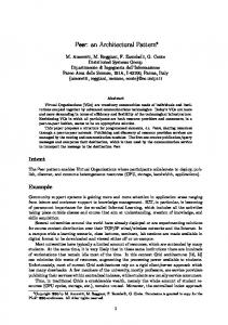
To illustrate the relationship between control and function, we consider the example of a communication system that uses the so-called “alternating bit protocol” [2]. The exact details of this protocol are beyond the scope of this paper; suffice it to say that it is a flow-controlled protocol that deals partially with the negative effects of unreliable communications medium (e.g., message duplication, reordering, and loss). A typical execution sequence of this protocol is depicted in Figure 1. Figure 1.
Alternating bit protocol — typical scenario
Server
Sender pkt(1)
Receiver pkt0 ack0
ack pkt(2)
pkt1 ack1
Client pkt(1) ack
pkt(2) ack
ack
The function of the system is to transfer information between two of its users: a Server and a Client who are interconnected by an unreliable communications network. The system itself consists of a Sender component collocated with the Server and a Receiver collocated with the client. The Server periodically formulates an information packet (pkt(x)) which it sends to the Client using the services of the Sender component. When it receives an acknowledgment (ack) from the Client (via the system), the Server transmits the next packet. To protect against reordering, duplication, or loss of messages, the Sender labels each information packet with a sequence number (0 or 1) and refrains from sending the next packet until the previous one has been acknowledged by the Receiver. To avoid confusion about which packet is being acknowledged, the Receiver includes the sequence number of the last successfully delivered packet in its acknowledgment. Thus, if a packet with a sequence number of zero was sent an acknowledgment with a sequence number of zero is expected. If the expected acknowledgment does not arrive within some predefined maximum time interval, the original information packet is resent by the Sender. For simplicity, we assume that the Server never sends a packet until the previous one has been acknowledged by the Client. This is a simple case of a two-level communication protocol in which a high-level protocol (Client-Server) is overlayed on a lower-level protocol (Sender-Receiver). The lower-level protocol hides some of the complexity of dealing with an unreliable communications medium thereby simplifying the implementation of the higher-level protocol. A common way of specifying the lower-level alternating bit protocol is through a pair of
2
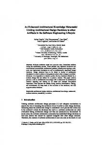
simple cooperating finite-state machines as shown in Figure 2. Figure 2.
Alternating bit protocol — formal specification SENDER
RECEIVER
Input1
Output1 ack0/ack
pkt1/pkt
pkt/pkt1
ack/ack1
Sent1 t.o./pkt0
Received1
Sent0 pkt/pkt0
t.o./pkt0
pkt1/ack1
ack1/ack
Received0 ack/ack0
pkt0/ack0
pkt0/pkt Input0
Output0 t.o. = timeout
In this form, the specification does not take into account a variety of practical control-related concerns that must be addressed. Let us assume that the following basic capabilities are also required of this system: •
Both the sender and the receiver need to be initialized with configuration data (e.g., address data that uniquely identifies each station). Let us assume that this data comes from a message sent by an external control entity.
•
For maintenance reasons, it is necessary to be able to restart (i.e., start the protocol from the beginning) the two entities without reloading the data. The restart command comes in the form of a message sent by an external control entity.
•
In some cases, it is necessary to fully reset the entire Sender/Receiver complex. A full reset requires that the configuration data be reloaded. The reset is also initiated by a message sent by an external entity.
•
To ensure proper synchronization of the two ends in case of resets and restarts, we will assume that neither the Sender nor the Receiver will commence with the protocol until they are explicitly directed to do so with an external start message.
•
If the Sender does not receive the expected acknowledgment from the Receiver after several retries (retries are initiated by time-outs (the t.o. triggers in Figure 2.), it should enter an error state from which it can be either restarted or reset. In this state, it no longer responds to the Receiver. Similarly, we could define an error state in the Receiver which is entered if it receives too many wrong signals in succession from the Sender. The purpose of the error state is to identify that the two ends of the protocol are hopelessly out of sync and that something needs to be done to resolve the deadlock.
The additional messages added to the specification are control signals that serve to properly synchronize the operation of the two ends in a realistic environment1. In effect, they represent a second protocol: the protocol between the Sender (or Receiver) and its immediate controller. If we abstract out the details of the alternating bit protocol as defined in Figure 2., then the process of controlling each of the two ends can be described by another state machine (Figure 3.). 1. In fact, only a limited set of failure modes are considered in this example; a real implementation would likely have to contend with additional ones.
3
Figure 3.
The control state machine for the Sender and Receiver
reset
Unconfigured
reset
config restart
Configured
restart
start Operational
“error”
Error
The “Operational” state in the above diagram does not really exist; it is just a shorthand notation for the two finite state machines in Figure 2. The actual complete diagram, for the Sender, is shown below in Figure 4. (to reduce visual clutter, the transition labels are not shown). Figure 4.
The complete state machine diagram of the Sender Unconfigured
Configured
Error
Input1
Sent1
Sent0
Input0 The most obvious difference between the specification of the Sender in Figure 2. and in Figure 4. is that the latter is much more complex. In general, the synthetic quality of a graphical rendering is lost in such cases because of excessive detail. Some of that complexity can be removed by various graphical “shorthand” tricks (e.g., constructs such as “any” state). Nevertheless, there still remains the issue that, in Figure 4., the alternatingbit protocol and the control protocol have become hopelessly intertwined even though they are defined independently of each other. Neither protocol is depicted in its “pure” form but in the context of the other protocol. This not only hinders understanding but also complicates maintenance. Someone who is not fully aware of the separate nature of the two protocols may, during maintenance activity, inadvertently couple them further or violate one while trying to fix the other. There is one other serious problem here. We have already noted that the control protocol for both the Sender
4
and the Receiver are practically the same. This is a common feature of well-designed control systems since it decouples the control system from the specifics of what is being controlled. Unfortunately, by merging the two protocols into a single super-protocol, the common control protocol needs to be reimplemented separately (“cloned”) for each controlled element. Furthermore, if the control protocol needs to be changed, the same modifications have to be manually propagated to each separate instance. This increases the amount of effort and the probability of coding errors.
3.
DEALING WITH CONTROL IN REAL-TIME SYSTEMS
Separating Control From Function In the previous section, we said that it was desirable to keep the control protocol as separate as possible from the functional protocol to allow the two to change independently. Note that in the example, we implicitly assumed that the object controlling the Sender was not the user of its services (the Server) but some other object. This is sound engineering practice that is based on the well-established principle of separation of concerns as well as for security reasons. To enforce this separation, it is helpful to separate the control interface of an object from its functional interface. Taking this one step further, we propose that the components of a system responsible for control be separated from those responsible for the functional (service) aspects. We call this the principle of separating control from function. The expected result of this decoupling is that the relative complexity of each of the two aspects will be reduced, and it will be easier to modify one without affecting the other. Implicit in the principle is the view that the two areas of concern are of equal significance. (In contrast to the widely held notion that control aspects are of secondary import.) This principle is taken directly from classical control theory where the responsibility for control is typically associated with a component called the “controller” that is distinct from (but connected to) the remaining “functional” parts of the system, as shown in Figure 5. Figure 5.
The classical control system model
controller
input
Functional Part
output
Separating Control Policies and Control Mechanisms Control strategies in many systems are prone to change. For example, a telephone switch that may have started as a stand-alone system, might later be integrated into a greater corporate communications network. This means that its internal control system would have to evolve from being an autonomous unit into an executive agent for a higher authority. To simplify and standardize the handling of such situations, we introduce another design principle, partly based on the prior one: in the design of the control aspects of a system, control policies should be kept distinct from control mechanisms. Control policies are realized by software that makes decisions based on state feedback and that issues control commands to secure those decisions. Control mechanisms, on the other hand, are the components that provide that feedback (“sensors1”) and that respond to commands (“actuators”). For example, in a communications system, a component that detects the failure of a transmission link is part of the control mechanisms. However, a component that does the fault recovery procedure would be part of the control policies. By cleanly separating the two, it becomes possible to change the recovery procedure without affecting the failure detection software.
The Recursive Control Pattern — Structure The Recursive Control pattern embodies the two design principles described above. The structural aspect of this pattern is illustrated in Figure 6. The purpose of the functional components in the canonical model is to provide 1. The terms “sensors” and “actuators” here typically refer to software entities (e.g. drivers) rather than actual hardware.
5
the required system functionality. This functionality is accessed through one or more functional interfaces of the system. The operational state of the functional components is controlled by the internal control component of the system. The control policy for managing the system may either be integrated into the internal control or it may come from an external higher-level control system through the control interface of the system. Note that although internal control is shown as a single monolithic component, it may be realized by a confederation of separate components. Figure 6.
The structure of the Recursive Control pattern control Interface System Internal Control
....
Functional Component1
Functional Componentn
functional Interfaces In these diagrams, we use the convention of explicitly rendering object’s interfaces by smaller squares that appear on the border of an object. For clarity, control interfaces are represented by white squares while filled black squares denote functional interfaces. The black line segments that connect object interfaces are abstractions of various types of inter-object links such as pointers, sockets, or pipes. Figure 7.
Recursive application of the pattern control Interface System Internal Control
Functional Component1
Int.Control
Func.Cmp
....
....
Func.Cmp
In this model, each functional component also has two sets of interfaces: a control interface to the internal
6
control system and one or more functional interface for the services it provides to its clients. The client interface of each of the n functional components is “exported” to the interface of the system. The net result is a system with one control interface and a number of functional interfaces. Note that, from the viewpoint of a functional components, the so-called internal control element acts as an external controller. This analogy suggests a recursive application of the pattern for complex functional components that need to be decomposed into simpler “subsystem” modules (Figure 7.). The recursive nature of the pattern means that, in principle, it can be used for arbitrarily complex systems.
Collaborations When a control input (e.g., reset) is received through the top-level control interface, the internal controller of the System translates this into one or more control inputs for a subset of the top-level functional components. If the functional components are decomposed further, these inputs are received by the internal controllers and are, in turn, resolved into yet finer control signals for their own functional subcomponents, and so on. In effect, the contained internal controllers provide a set of control mechanisms for realizing the control policies of their higher-level controllers. In the reverse direction, functional components notify their controllers whenever they detect a control situation, such as various types of component failures, that requires intervention by their controller. Functional components also collaborate with external clients to provide their respective services.
Applicability Recursive Control is useful in situations, typical in event-driven real-time applications, where a complex software-based server system needs to be controlled dynamically in some non-trivial manner. It is particularly applicable in situations where there is a high likelihood that control policies may change over time.
Participants •
Internal Control accepts control inputs received from external (higher-level) controllers, through the system’s control interface, and, based on its inherent control policies, resolves these into control commands for the functional components directly under its control. It also reacts to internal events that emanate from the controlled functional components. These responses may be purely local, based on the control policies built into the controller, or they may result in control events that are relayed on to the higher-level controller for handling. For completely autonomous systems, there may not be a control interface at the top level.
•
Functional Components provide the basic service functions of the system through one or more functional interfaces as well as a set of mechanisms for effecting the control policies of their controllers. They are also responsible for administering internal control policies (e.g., through their contained internal controllers) for control situations that do not require intervention by their controllers. If they are complex enough, functional components may be further decomposed into an internal control and a set of lower-level functional components.
Consequences The Recursive Control pattern •
increases the likelihood that software control issues will be properly addressed in the design of complex real-time software.
•
greatly simplifies the implementation of complex systems since it is based on a recursive application of a single structural pattern. In essence, it provides the basic architectural structure for such systems at all levels of decomposition from top to bottom.
•
simplifies the development (and understanding) of both functional and control aspects by decoupling them from each other to a large extent.
•
allows control policies to be changed without affecting the basic functionality of the system.
Relationship to More Basic Patterns The Recursive Control pattern is a combination of other more fundamental patterns. The principle of separating
7
control from function is an embodiment of the Strategy pattern as defined in [3]. The main idea behind this pattern is to protect a client from having to contend with implementation differences in a strategy (service) that it requires. The Control component of the Recursive Control pattern plays the role of the Context in the Strategy pattern. It delegates the realization of its control strategy to the different functional components (the concrete strategies) through a common interface. Structurally, the Recursive Control pattern is related to the Composite pattern described in [3]. Composite is a recursive pattern that is used in situations where it is necessary to treat components uniformly, regardless of whether they ar primitive or composite objects. Figure 8.
Recursive Control as a variant of the Composite pattern
AbscontroledComp
LeafFuncComp
System
InternalControl
The structural diagram of Recursive Control is shown in Figure 8. Note that, since all the participants in this pattern have a common control interface, they are all subclasses of a common abstract class (AbscontroledComp). One of those subclasses is System, that represents the control-function structure. It consists of exactly one InternalControl component and a number of leaf functional components (LeafFuncComp) or lower-level Systems. From a behavior perspective, Recursive Control incorporates the Chain of Responsibility pattern ([3]). Namely, external controllers issuing control inputs are unaware of the hierarchy of internal controllers that are actually responsible for executing the corresponding control actions — they simply issue commands to the System through its unique control interface.
4.
IMPLEMENTING RECURSIVE CONTROL
We now look at how the Recursive Control pattern can be implemented. In particular, we show how hierarchical state-machine formalisms, such as statecharts[4] or ROOMcharts [1], which are commonly used for modeling complex event-driven systems, can be used to great advantage for this purpose especially when they are combined with the inheritance mechanism. Hierarchical finite-state machine formalisms allow an entire state machine to be abstracted into a single state at the next higher level of abstraction. This allows very complex event driven behavior to be modeled by a graduated series of hierarchically related state machines. For example, either of the state machines in Figure 2. (Sender or Receiver) can be subsumed into the “Operational” state of the control state machine in Figure 3. The resulting top-level state machine for both objects is depicted in Figure 9. using the ROOMchart notation. (The two transitions, reset and restart emanating from the border containing the state machine are a shorthand way of saying that these transitions can originate in any state.)
8
Figure 9.
The top-level state machine for the Sender and Receiver
top
I
reset
Unconfigured
config restart Configured
start Operational
“error”
Error
For a controlled component to perform its function, it must first be in the appropriate operational state. In our alternating-bit protocol example, both the Sender and the Receiver first had to pass through the Configured state (where they received their configuration data) and be explicitly activated (for synchronization reasons) before they could perform their primary function. This means that in specifying behavior, control predicates function. That is, the dominant, or upper-level behavior is the control framework; it subsumes (encapsulates) the functional behavior. Note that both the Sender and the Receiver have the same top-level behavioral specification. However, they have different functional state machines represented by the left and right sides of the specification in Figure 2. It appears as if the two objects would require two separate state machines that have the same top-level state machine but that differ in the way that the Operational state is decomposed. (The hierarchical nature of the Operational state is indicated graphically by its thicker border.) At this point, we can take advantage of inheritance and define a class hierarchy such that the two have a common abstract class that captures the top-level behavior and two distinct subclasses for the Sender and Receiver (Figure 10.). In the abstract superclass (LeafFuncComp which inherits from AbsControledComp, as shown in Figure 8.), the Operational state is a simple leaf state, but, in the subclasses, it is refined into submachines. For the Sender subclass, the submachine will correspond to the left-hand side of Figure 2. while, in the Receiver subclass, the submachine matches the right-hand side of Figure 2. In effect, the Operational state is an abstract state analogous to a C++ virtual function. (The use of virtual functions or their equivalent for this purpose would be the most natural technique for applications that are not directly implemented as state machines.) In fact, as shown in Figure 10., the same abstract class can serve as a parent for any components, regardless of their place in the system hierarchy, that conform to the same control protocol. This not only saves development time and simplifies maintenance, but also encourages uniform control strategies ultimately leading to systems that are easily controlled. The net result is a more reliable system that can be produced with significantly less effort than through conventional development techniques. Note that this use of inheritance is actually a form of the Template Method pattern as defined in [3].
9
Figure 10.
The inheritance hierarchy for the alternating bit protocol LeafFuncComp config () start () restart () reset ()
Sender config () start () restart () reset () ack0 () ack1 () to () pkt ()
Receiver config () start () restart () reset () ack () pkt0 () pkt1 ()
Other Controlled Component classes
Consider next the case of a more complete system that is distributed across two processing nodes as shown in Figure 11. The ServerNode contains the Sender as well as the Server application that uses the Sender (see Figure 1.), while the ClientNode contains the Client and the Receiver. To ensure proper operation of the functional components in each node, we introduce an internal NodeController component. Among other things, this component ensures that the Sender (Receiver) is activated before the Server (Client). Using the same rationale, we also introduce a supercontroller component, the SystemController, which synchronizes the operation of the two nodes. For example, if the server node fails for some reason the SystemController controller would notify the client node so that proper recovery action can be undertaken (e.g., switching to another server). Figure 11.
The Client-Server system example
CSSystem SystemController
NodeController
NodeController
Server
Client
Sender
Receiver
ServerNode
ClientNode
10
The structure shown in Figure 11. is, in fact, an application of the Recursive Control pattern. In this case, the SystemController and the NodeControllers are both examples of internal controllers although they occur at different levels of decomposition. However, they can both be subclasses of the same abstract class, InternalControl (Figure 10.). The Sender, Receiver, Server, and Client components are all different subclasses of the LeafFuncComp abstract class while the two aggregate node components, ServerNode and ClientNode, as well as the overall CSSystem are different subclasses of the abstract class System. The operation of the control hierarchy can be illustrated using the boot scenario sequence: At start-up time, all components automatically come up in the Unconfigured state as shown in Figure 9. Once the CSSystem controller is fully activated (since this is the “top” level of the system, this could either be driven by a higherlevel external control system or it could be automatic), it proceeds to activate the two node controllers in the proper sequence (for example, activating first the server node and then the client node controllers). When a node controller is activated, it can in turn activate its corresponding functional components in order. Analogous activities occur in other control situations such as component failures and controlled shutdown.
5.
SUMMARY
In the design of real-time software it is standard practice to treat control functions as second-level concerns despite the fact that such aspects often represent the greater portion of the overall software. This often leads to unnecessary complexity with diverse and inconsistent control policies at different levels of the system and where the control and functional aspects of the system are inextricably coupled so that they cannot be understood or modified independently. This has negative impacts on system reliability and maintainability. In this paper we have introduced a design pattern, called Recursive Control, that helps avoid these problems for practically any real-time system where there is a need for dynamic control. One of the characteristics of this pattern is that system service functionality is encapsulated within its control functionality. This is reasonable when one takes into account that a system must first reach an “operational” state before it can properly perform its service function. Thus, the Recursive Control pattern reverses traditional design practice and places control before function. An important feature of the pattern is that it can be applied at any level of decomposition including the top level (hence, it is an “architectural” pattern). If the pattern is applied recursively and uniformly, the result is a system that is both simple and highly controllable. The Recursive Control pattern can be expressed particularly concisely and effectively if inheritance is used to capture common control behavior in an abstract class.
REFERENCES [1] B. Selic, G. Gullekson, and P. T. Ward, Real-Time Object-Oriented Modeling, New York: John Wiley & Sons, 1994. [2] K. Bartlett, R. Scantelbury, and P. Wilkinson, “A note on reliable full-duplex transmission over half-duplex lines,” Comm. of the ACM, vol. 12, no. 5, pp. 260-265. [3] E. Gamma, R. Helm, R. Johnson, and J. Vlissides, Design Patterns: Elements of Reusable Object-Oriented Software, Reading, MA: Addison-Wesley, 1994. [4] D. Harel, “Statecharts: A visual formalism for complex systems,” Sci. of Comp. Programming 8 (July 1987), pp. 231-274.
11