An Architecture and a Programming Interface for ApplicationAware Data Dissemination Using Overlay Networks Tarun Banka1, Panho Lee1, Anura P. Jayasumana1, Jim Kurose2 1
{leepanho, tarunb, anura}@engr.colostate.edu,
[email protected] Department of Electrical and Computer Engineering, Colorado State University, Fort Collins CO 80523 USA 2 Department of Computer Science, University of Massachusetts, Amherst MA 01003 USA
Abstract - Many real-time distributed collaborative applications are emerging that require exchange of critical sensor data among geographically distant end users under resource-constrained network conditions. The QoS requirements, e.g., required bandwidth, latency, acceptable data quality, and reliability are interdependent, and critical to the operation of these applications. This paper presents an AWON (Application-aWare Overlay Networks) architecture for deploying application-aware services in an overlay network to best meet the application requirements over the available overlay networking infrastructure. An application programming interface (API) is presented to facilitate development of applications within the AWON architectural framework. The API supports the configuration of overlay nodes for in-network, application-aware processing. Application-defined plug-in modules are used to deploy applicationspecific functionality at each overlay node. The API also enables communication between application and the overlay routing protocol for the desired QoS support. The effectiveness of the AWON architecture and the API is demonstrated for a real-time weather radar data dissemination application using planetlab. Experimental results show that AWON-based application-aware services significantly improve the quality of the content delivered to the end users in bandwidth-constrained conditions. 1.
Introduction
Distributed collaborative adaptive systems relying on the Internet for connectivity are increasingly used for applications such as weather monitoring, industrial environment monitoring, and distributed target tracking [13, 16]. In many of these applications, a variety of data must be distributed in real time to multiple end users at distant geographical locations. These data streams and end users may have differing QoS requirements for the data based on the ultimate use of the data. The data-dissemination infrastructure must therefore be able to adapt in an application-specific manner to meet these differing data requirements. Collaborative Adaptive Sensing of the Atmosphere (CASA) [16], an example of these emerging distributed collaborative adaptive systems, is based on a dense network of weather radars that operate collaboratively to detect tornadoes and other hazardous atmospheric conditions. The underlying network infrastructure itself may be affected by such adverse weather conditions, and as such one cannot rely on ISP-provided QoS guarantees or service-level agreements. CASA application software must thus monitor the underlying network, link availability, link quality, and other performance measures, and then use this information to get the best possible service out of
the available network facilities. The use of an overlay network paradigm is helpful in meeting such application needs. Application-aware processing such as selective frame discards for video streaming has shown promising results in improving the content quality [9] under congested network conditions. However, adaptive data-selection mechanisms in traditional applications based on end-to-end data delivery relied on end-host applications to adapt to network conditions [2, 9, 21]. Active networks [20] introduced the concept of innetwork processing, where routers and switches of the network perform customized computations on messages being forwarded. Overlay networks have been proposed to provide a range of useful services for enhancing QoS for Internet applications including bandwidth guarantees [1,3,11,19,22]. With overlay networking, application-aware processing can be implemented at intermediate nodes, thus significantly enhancing the ability of the application to adapt to network conditions and improve the QoS provided to the end users. Examples of these functionalities include application-aware data forwarding and data drops, as well as application-aware rate control during network congestion at intermediate nodes [7]. It is often desirable to use the same overlay infrastructure for multiple simultaneous applications such as weather radar data streaming, and video streaming to multiple end users. A general-purpose overlay architecture that supports deployment of application-aware services on the overlay nodes in the network, and a programming interface required for such services that can leverage such an overlay network infrastructure to support application-specific QoS requirements will significantly enhance the overlay-based application deployment. This paper proposes the AWON (Application aWare Overlay Networks) architecture for application-aware overlay networking, and presents a general purpose programming interface. The AWON architecture and the API presented in this paper allows the applications to regulate the flow of data through overlay nodes in an application-aware manner, selecting data to be forwarded, and extracting/repackaging data, taking application-specific constraints into account. A significant amount of research has been done on the design and development of overlay routing protocols to improve an underlay network’s resilience and performance [3,14,18]. Our work complements and takes advantage of such ongoing research effort of performing QoS-aware routing in
This work is supported by the Engineering Research Center program of the National Science Foundation under NSF Award No. 0313747
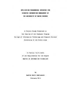
Figure 1. Overlay network for application-aware data dissemination
overlay networks such as RON[3]. OverQoS[19], an overlaybased architecture can provide a variety of QoS-enhancing innetwork services in the intermediate nodes of overlay networks, such as eliminating the loss bursts, prioritizing packets within a flow, and statistical bandwidth and loss guarantees. Our work is motivated by the same vision of enhancing QoS support within the network without the support from IP routers. An important difference between the AWON and the OverQoS architectures is that in the AWON-based approach, quality of service provided to an application is enhanced by performing application-aware processing within the network. Moreover, the AWON architecture is highly flexible and can accommodate QoS requirements of large class of applications. OCALA [10] and Oasis [15] enable the users of legacy applications to leverage overlay functionality without any modifications to their applications and operating systems. Opus [8], which is motivated by active networking, provides a large-scale common overlay platform and the necessary abstractions to service multiple distributed applications. In contrast to our work, Opus focuses on the wide-area issues associated with simultaneously deploying and allocating resources for competing applications in a large-scale overlay networks. XPORT[17] is a tree-based overlay network, which can create dissemination trees based on diverse performance requirements of the applications. Section 2 provides motivation for AWON and the programming interface for overlay networks. Section 3 explains the AWON architecture for deploying applicationaware services in overlay networks. Section 4 describes the API. Section 5 describes the flow of API calls to support the AWON architecture. An example implementation is illustrated in Section 6. Section 7 presents Planetlab-based experimental results that demonstrate the effectiveness of the AWON and the corresponding API for weather radar data streaming. Conclusions are presented in Section 8. 2.
Motivation
Applications relying on overlay-based implementations to achieve performance, reliability and other application specific
requirements must be able to configure overlay nodes to perform in-network application-aware processing. A flexible, efficient approach for the deployment of QoS-sensitive applications using overlay networks should facilitate the monitoring of the QoS received by an application in the overlay network, and allow easy deployment of applicationaware processing at intermediate overlay nodes. A framework is thus required for realizing such application-aware overlay networks. A programming interface is needed to facilitate development and deployment of applications within this application-aware framework. The API provides a layer of abstraction between an application and the underlying dynamics of the network infrastructure. It is desirable for the API to support application-aware adaptation in the overlay network, with each participating node possibly performing different applicationaware operations to meet the overall goals of the application(s). The API must support node configuration in an applicationaware manner, with each node being configurable to support multiple applications concurrently. There is also a need for communication between the application and the underlying overlay layers for supporting application-specific QoS requirements [3,4,19,22]. For this to be realized, the API must allow an application to specify its QoS requirements to the system. When the underlying system is able to accept the application with its QoS requirements, the API should be able to communicate this acceptance to the application. In Sections 3 and 4, we describe AWON architecture and its API respectively. We consider a weather-monitoring network application to illustrate the need for an application-aware architecture and a programming interface for such overlay networks. 3. Application Aware Overlay Network (AWON) Architecture Fig. 1 shows an application-aware overlay network for distributing data to multiple sink nodes with different end user requirements such as data quality and bandwidth requirements. Let us now illustrate the myriad roles overlay nodes may play in meeting application requirements. In Fig. 1 source nodes 1-3 may perform application-level packet-marking to indicate the usefulness of the data to a particular application; nodes colored blue (nodes 1-5) may perform packet forwarding/drop based on the marking done by the source node; nodes colored green (multicast nodes 4, 7, and 8) may distribute data to multiple end users and perform independent congestion control for each end user in an application-aware manner. The multicast nodes combine the requests from the end users and send an aggregate upstream request to the specific source node. If the network experiences congestion, congestion-based packet (information) discard can be performed at the source or at intermediate nodes, according to the available bandwidth. A source node can thus mark packets based on the relative importance of the information sent to the multicast nodes 4, 7, and 8. This facilitates application-aware selective drops (rather
2
Select Next Hop
Transmit Packet
QoS Manager
onl_send()
onl_recv()
onl_QoS()
onl_send()
` Application Manager
Select Next Hop
Transmit Packet
Overlay Routing Layer
Application Plugin 3 Multicasting Congestion Control
message_send() message_recv()
Application Plug-in 2 Data Forwarding
recv_upcall()
Application Plug-in 1 Data Selection and Marking Congestion Control
Application Aware Processing
AWON Architecture of an Overlay Node
Figure 2. AWON architecture for application-aware data dissemination using overlay networks – An example node with multiple plug-ins
than random drops) within the network. Intermediate forwarding nodes 1-5 may use this marking information at the time of forwarding during network congestion. Similarly node 6, a fusion node, may combine data from multiple sources to reduce the downstream data bandwidth requirements. In addition to the packet handling functions discussed above, there are two other classes of functions a node may implement. First, there is a need to support multiple applications simultaneously on the same overlay network. Also, it may be necessary for an application to track performance of the underlying networking infrastructure in meeting the application requirements. Fig. 2 shows the AWON architecture to support application-aware data-dissemination services. There are two key components of the AWON: (i) Application Manager, (ii) Application Plug-ins. Each of these components focuses on two different areas of functions with a common goal of providing best effort QoS services to the applications and providing a layer of abstraction to the application developers. Application developers are not required to be aware of other applications deployed on the same node. Moreover, they need not be aware of the implementation of the underlying overlay routing infrastructure. (i) Application Manager: The key responsibilities of the application manager are: 1. De-multiplexing packets received for different applications at the same node 2. Logging QoS status information for each application and informing (when appropriate) the underlying overlay routing layer about the QoS status/requirements of the applications 3. Authorization of a new user in the system based on a local policy
(ii) Application Plug-ins: In the application-aware paradigm, each application is required to configure its functionality in the participating overlay nodes. The AWON architecture supports application-specific plug-ins that implement the functions performed by the participating overlay nodes in the data dissemination. For a particular application, multiple nodes can play different roles, motivating the need to deploy relevant plug-ins on those nodes that implement particular functions. For an example, with a collaborative radar application [16], the source node in Fig. 1 has application plug-in 1 shown in Fig. 2 for supporting data selection and marking. Similarly nodes 1-5 in Fig. 1 may have application plug-in 2 to support application-aware forwarding based on the source’s marking. Nodes 4, 7, and 8 may have application plug-in 3 to support application-aware multicasting and congestion control. Note that the same node may have multiple plug-ins to support multiple functions performed by a node for a given application. For an example, in Fig. 1, node 4 acts as a forwarding node and a multicasting node for the same application. As seen in Fig. 2, the AWON architecture requires communication between application-manager and plug-ins, application manager and routing layer, and between plug-ins and routing layer. Section 4 describes the programming interface to support deployment of application-aware services using AWON. 4.
Application Programming Interface
Following are the key goals of the application programming interface: (i) (ii) (iii)
Enable deployment of application-aware services on the overlay network infrastructure. Provide real-time monitoring of the QoS status of the application. Facilitate communication between application-manager and plug-ins, application manager and routing layer, and between plug-ins and routing layer.
There are three broad categories of the API calls to deploy applications within the AWON framework: 1. API calls for node configuration 2. API calls for communication between application plug-ins and application manager 3. API calls for communication with overlay routing layer 4.1. API calls for node configuration: As shown in Fig. 1 and Fig. 2, each participating node from source to the destination may play a different role for a particular application. The app_config() API is used to perform node configuration for a particular application: int app_config (app_id, plug-in()): app_config() is used by the application developer to deploy application specific functionality at all the participating overlay nodes. For a given application, a unique application identification app_id is defined and is used as an input parameter. An app_id value of
3
0 is reserved for the special case of the application manager module. It is important to note that app_id is a globally unique identifier for a given application deployed over the overlay network. However, the plug-in() function reference parameter may be different for different nodes. The functionality of the plug-in() function depends on the application-specific function to be performed by a particular node during data transfer. The API allows the same overlay node to be concurrently used for multiple applications. Therefore, app_config() can be called by different applications with different app_id parameter to configure the operation of the node to meet application-specific requirements. 4.2. API calls for message exchange between user application and application manager: An API is required for three different types of messages that are exchanged between application plug-ins and the application manager as shown in Fig. 2: (i) Packets received by the application manager from the overlay routing layer for the user applications (ii) Authorization messages to allow new users in the system (iii) Periodic exchange of application-specific QoS messages We define three API calls for message exchange between an application and the application manager, message_send(), message_recv(), and recv_upcall(). int message_send(dest_app_id, msg_buff): As shown in Fig. 2, the message_send () API is used by the application manager and the application plug-in module to send messages to each other within the same node. It accepts two input parameters, dest_app_id and msg_buff. dest_app_id is a unique destination application identifier. msg_buff is the actual
int message_recv(src_app_id, msg_buff): As shown in Fig. 2, message_recv() is used by the application plug-in and the application manager to receive messages from each other. It accepts two arguments, src_app_id and msg_buff. src_app_id is the source application id of the message sender. If the source is the application manager then src_app_id is 0 otherwise it is a positive integer when source is an application plug-in. msg_buff contains the copy of the message received from the sender side. Now we explain msg_buff format in detail as follows: Fig. 3(a) shows the format of the msg_buff. Following are the fields of msg_buff as shown in the figure: Application Id: This is the unique application id of the sender application. Message Type: There are three types of messages that are exchanged between application manager and the plug-in modules depending on the context. This field can be QosRequest, QosAccept, or QosStatus. Length: The Length field indicates the size of the msg_buff that includes variable length message field. Message: The message field content varies with message_type. When the message type is QosRequest, the message field contains target_bw, minimum_bw, and latency requirement fields. Alternatively, when the message type is QosAccept or QosStatus, message field stores TRUE or FALSE flags. void recv_upcall(app_id, pkt_buffer, length): The recv_upcall() API is used by the application manager to deliver a received packet from the overlay routing layer to the appropriate application. It accepts three input parameters: app_id, pkt_buffer, and length. app_id refers to the application identifier of the application for which packet is received, pkt_buffer is the pointer to the packet received from the overlay routing layer, and the length field denotes the size of the pkt_buffer. 4.3.
Message Format
Application Id
Message Type Length
Message
(a)
message sent to the destination node. It returns 1 when message is successfully transmitted otherwise it returns 0.
(b)
Figure 3. (a) msg_buff format used for communication between application manager and application plug-ins. (b) pkt_buff format an example
API calls for routing layer
communication
with
overlay
An API is also required to support communication between the overlay routing layer and the application plug-ins, and to support communication between the overlay routing layer and the application manager. As seen in Fig. 2, the AWON architecture requires the following communication support: (i) Packet delivery from an application plug-in to the overlay routing layer (ii) Packet delivery from the overlay routing layer to the application manager (iii) Exchange of an application’s QoS requirements with the overlay routing layer To support these requirements, we define three APIs under this category, onl_send(), onl_recv(), and onl_QoS().
4
int onl_send(dest, pkt_buff, length): The onl_send() function is used by an application to transmit application data using the overlay routing protocol. It accepts three input parameters dest, pkt_buff, and length. dest refers to the destination address of the packet, pkt_buff is the pointer to the application packet buffer, and length indicates the size of the pkt_buff. It returns 1 when packet is transmitted successfully and returns 0 otherwise. The onl_send() selects the next hop for transmission based on the overlay routing protocol implementation. Alternatively, the application may use overlay source routing to route packets through pre-determined paths. Under most circumstances pkt_buff should contain app_id, source, and destination addresses. Fig. 3(b) shows a possible structure of the application packet, i.e., pkt_buff. All non-shaded fields are configurable and can be determined based on applicationspecific characteristics and in conjunction with the overlay routing protocol used in the network. The different packet fields shown in Fig. 3(b) are as follows: Source: The unique address of the source node. Destination: The address of the remote sink node or the next hop in the path from source to the destination sink node. Application Id: The unique application identifier which is set by the application plug-in module at the time of transmission. Version: Current version of the packet format. Application Packet Type: Depending on the application, this field is used to indicate the contents of the packet data. Some of the possible packet types are: DATA, ACK, REQUEST, TERMINATE. Routing Packet Type: Depending on the routing protocol implementation, this field is used to define different packet types that can be used by the routing protocol to select the next hop for routing the application packet. Some of the possible routing packet types are SOURCE_ROUTING, QOS_ROUTING. Total Length: The size of the packet in bytes. Application Data Length: The size of the Application Information field in the packet in bytes. The value of this field may vary from application to application, and can also vary from packet to packet within the same application. Routing Information: The contents of this field are defined based on the overlay routing protocol implementation. For example, when QoS-aware routing is supported, then an overlay routing protocol may store QoS requirements that should be considered for the next hop selection. When source routing is used, then this field includes the complete path to be followed between source and the destination node. Application Information: The content of this field is determined by the application transmitting the data. It may contain application-specific header and data payload. Some of the possible application-defined fields are sequence number, packet marking, QoS requirements, and metadata. int onl_recv(pkt_buffer) : As shown in Fig. 2, the onl_recv() API call is used to receive data from the overlay routing protocol layer. It accepts one argument, pkt_buffer, which is a pointer to the packet received from the overlay routing layer.
Figure 4. API calls Example
Based on the application id field in the received packet, the packet is demultiplexed to the appropriate application using recv_upcall() as explained earlier. When a packet is received successfully, onl_recv() returns length of the packet otherwise -1 is returned. void onl_QoS(app_id, bandwidth, latency): As shown in Fig. 2, the onl_QoS() API is called by the application manager to inform the overlay routing layer of an application’s QoS requirements. It accepts three input parameters, app_id, bandwidth, and latency. app_id is the application id for which QoS requirements are specified, bandwidth is the minimum bandwidth requirement of a particular application, and latency is the maximum latency that an application may tolerate. 5.
Summary of API Calls
Fig. 4 shows the API calls that may be made on an overlay node to support application-aware services. app_config() configures a particular overlay node by deploying applicationspecific plug-in modules. An application plug-in module may call message_send() and message_recv() to exchange control information with an application manager. An application may send a QosRequest message to the application manager before accepting a request from any new user. A module may also periodically exchange application-specific QosStatus information with the application manager. As shown in Fig. 4, the application also uses the onl_send() to send packetsto the underlying overlay routing layer. As mentioned earlier, the application manager uses message_send() and message_recv() to exchange control information with the application plug-ins. In particular, the application manager sends authorization messages to the application plug-in for accepting or rejecting requests from new users. The application manager uses local policy to determine the type of authorization messages. The application manager communicates with the overlay routing layer using the onl_QoS() and onl_recv() interfaces. As shown in Fig. 4,
5
SOURCE NODE
MULTICAST NODE
Application Plug-in for Server
Application -Aware Framing & Marking
Select Frames
Determine Current Rate
Select & TX Frames
Application Manager
Application Plug-in for Multicast User List
QoS Monitor
User Authorization
User QoS Request Authorization
User QoS Request Authorization Application Manager
Periodic QoS Status Report QoS Request
Packet Rx Feedback
QoS Manager & Select Next Hop
QoS Manager & Select Next Hop
Figure 5. Implementation example based on AWON architecture.
Overlay Routing Layer
Application Packet
QoS Request
Packet Rx
User Authorization
Receive Packet & Generate Feedback
Periodic QoS Status Report
Request Packet
QoS Monitor
Marking Based Selection and Token Bucket Rate Control
Application Packet
User Data
Application-aware Processing
Sensor Data
is used to request the overlay routing layer to adapt its operation for meeting application specific QoS requirements. The application manager uses the onl_recv() interface to receive a packet arriving at the overlay node from the network. As seen in the figure, a received packet is demultiplexed to the application plug-in module by calling recv_upcall() interface. 6. AWON Implementation Example for the CASA Application
Figure 6. Application-aware framing and packet marking. Each non-white color represent rate for which packet is marked ,i.e., rate R1-R8 [12].
when the application manager determines that the application is not meeting its QoS requirements, the onl_QoS() interface
To demonstrate AWON capabilities, let us consider a CASA application as shown in Fig. 1, where data from a radar source node is distributed to multiple end users with distinct bandwidth and data quality requirements. In this application, an application-aware multicast node receives data from the source node for further distribution to multiple end users. AWON architecture is used to perform applicationaware processing at source nodes and multicast node to best meet the QoS requirements of multiple end users. Fig. 5 shows the implementation details of a source node and a multicast node based on the AWON architecture. Both nodes use application-specific plug-ins to implement application-specific functionalities. The application manager implementation is same for all nodes in the overlay network.
6
As shown in Fig. 5, the source node plug-in implements application-level packet marking and a rate-based congestion control algorithm. Packet marking determines the subset of the information that should be transmitted at a lower transmission rate for acceptable data quality at the receiver end. Fig. 6 explains the marking scheme used in the current implementation [12]. Consider an example as shown in Fig. 6, where a sensor node generates 8 application data units (ADU) within the bounded time at rate R1. The ADU is defined as a fundamental application data entity that can be used by an end user algorithm for processing. Each row in Fig. 6 shows the subset of ADUs that are selected for transmission at a lower transmission rate when a higher rate cannot be supported because of bandwidth constraints. The subset of data selected at lower rate depends on the end user data quality requirements. For example, certain end users need uniformly spaced ADUs when only a subset of the data can be selected for transmission. Alternatively, other end users prefer a contiguous group of ADUs when bandwidth is constrained. Consider the case when the source node transmits data at rate R1, and as seen in the figure the data transmitted at lower rates is a subset of the data transmitted at rate R1 and ADUs are selected uniformly at lower rates. The packet containing ADU 1 is marked with different color flags corresponding to different rates, i.e. rates R1-R7. Similarly packet containing ADU 3 is marked with different colors corresponding to different rates, i.e., R1, R2, R4, and R5. As shown in the Fig. 6, every packet contains a flag for each rate for which it is transmitted indicated by different colors. Note that multiple flags can be set to indicate suitability of the packet for multiple transmission rates. The QoS monitoring component of the plug-in monitors the quality of the service received by the application users at a source node. Currently, the component monitors whether end users’ bandwidth requirements are met. The multicast application plug-in supports application-aware rate control using a token-bucket scheme and on-the-fly forwarding of data based on the packet marking. More information on the packetmarking and token bucket scheme used for the implementation can be found in [12]. This application-specific plug-in selects data for forwarding based on the available network bandwidth and the packet marking for multiple end users. Note that the packet marking performed at the sender node determines the priority of the packet to be forwarded at the multicast node. In such systems, each end user may need a different subset of the data from the radar source based on the intended use of the data [6,7]. During network congestion, overlay nodes can perform a better job by selectively dropping [2,7,9,21] packets (information) instead of dropping randomly within the network, taking into account end-user requirements for different subsets of the data. Similarly, other nodes participating in the data transmission can play different roles and thus may have different plug-in implementations. For example, if a node is configured as a simple forwarding node for a particular application, then the application plug-in forwards the data to its overlay routing layer for further
processing. The overlay routing layer may then select the next hop for the transmitted packet based on the local policy. If QoS-aware routing is supported, the next hop may be selected based on the application’s QoS requirements. Alternatively, when source routing is used, the routing protocol would select the next hop based on the path information included in the packet. 7.
Performance Evaluation
In this section, we demonstrate the effectiveness of AWON architecture and the API for implementing and deploying realtime applications on overlay networks such as planetlab [23]. Application: We consider a mission-critical CASA [16] application for the performance evaluation. One of the requirements of CASA application is to distribute high bandwidth real-time weather radar data to multiple end users [7] with distinct critical bandwidth and data quality needs. For such applications, it is not only important to meet the bandwidth and latency requirement, it is also important to meet the minimum content-quality requirement for the proper operation of the system. For example, each CASA end user may specify its critical minimum rate (MR) requirement that should be met for the proper operation of the system. Moreover, each end user may also dictate a target rate (TR), i.e., the maximum rate at which data can be received by the end user. A source node periodically generates a block of digitized radar data, referred to as a DRS block [5, 6]. Each end user specifies its content-quality requirement in terms of tolerance towards bursty losses or uniform losses within the DRS block. In the current implementation, we consider a case in which all end users prefer uniform drops of information instead of bursty drops within a DRS block. In case of our CASA application, during network congestion, the desired
, =8 TR
M
=4 R
,M =9 TR
=5 R
TR =4 ,
M
R =2
Figure 7. Planetlab test-bed for application-aware multicasting
7
Impact of Application-awareness on the Content Quality -End User 5 TR=4Mbps and MR=2Mbps (Experiment 1 - 3.88 Mbps, Experiment 2 - 3.85 Mbps, Experiment 3 - 3.87 Mbps)
2.5
Standard Deviation
Standard Deviation
Impact of Application-awareness on Content Quality - End User 1 TR=7 Mbps, MR=4 Mbps Experiment 1 - 6.78 Mbps, Experiment 2 - 6.70 Mbps, Experiment 3 - 6.72Mbps 3
2 1.5 1 0.5 0 141
142
143
144
145 146 Gates
147
148
149
3.5 3 2.5 2 1.5 1 0.5 0 141
150
Frequency of Marked Packets
Frequency of Marked Packets
20000 10000 0
150
(b)
70000
30000
148 149
Impact of Application-awareness on the Content Quality -End User 5 TR=4 Mbps and MR=2 Mbps (Experiment 1 - 3.88 Mbps, Experiment 2 - 3.85 Mbps, Experiment 3 - 3.87 Mbps) 35000
Frequency of Marked Packet - End User 1 TR=7 Mbps, MR=4 Mbps Experiment 1 - 6.78 Mbps, Experiment 2 - 6.70 Mbps, Experiment 3 - 6.72Mbps
40000
146 147
No Application-Awareness - Experiment 1 Application Aware Source - Experiment 2 ApplicationAware Source node and Multicast Node - Experiment 3 Base Case
(a)
50000
144 145
Gates
No Application-Awareness - Experiment 1 Application Aware Source Node - Experiment 2 Application Aware Source Node and Multicast Node - Experiment 3 Base Case
60000
142 143
30000 25000 20000 15000 10000 5000 0
4
5
6 7 Rates (Mbps) No Application-awareness - Experiment 1 Application Aware Source Node - Experiment 2 Application-aware Source and Multicast Node - Experiment 3
(c)
2 3 4 Rate (Mbps) No Application-awareness - Experiment 1 Application-aware Source Node - Experiment 2 Application-aware Source and Multicast Node - Experiment 3
(d)
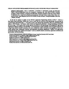
Figure 8. Impact of application-aware architecture on the content quality delivered to the end user s (a) Standard deviation of data for end user 5 with low bandwidth requirement TR=4, MR=2, (ii) Standard deviation of data for end user 1 with high bandwidth requirement TR=7, MR=4. (c) Marked packet frequency for end user 5, (d) Marked packet frequency for end user 1
rates are between MR and TR and the desired packets are those that contain subset of the DRS block of data with uniform drops. All these selected packets are marked for rate between MR and TR at the source node. We implement this application using the AWON architecture, as it enables application-aware processing within overlay nodes to enhance the QoS under dynamic resource-constrained conditions. Overlay Network Topology: Fig. 7 shows the Planetlabbased overlay network topology used for application-aware data distribution and performance evaluation. It consists of 11 overlay nodes, each configured to perform application-specific tasks to meet the overall QoS requirements of the application. In Fig. 7, there are four different types of nodes that are present in the overlay network - a source node, a multicast node, a forwarding node, and an end user node. The source node performs selective data drop during network congestion as well as application-aware packet marking based on the end user’s data quality requirement as explained in Section 6. The goal of the marking scheme is to deliver the most appropriate subset of data for the end user under congested network conditions. The forwarding node may decide to forward a packet based on a packet’s marking and the available downstream link bandwidth. The multicast node performs on-
the-fly selection of the data for forwarding based on packet marking to the respective end users at the current transmission rate. The multicast node uses TRABOL (TCP-Friendly Rate Adaptation Based On Losses), a UDP-based rate-based congestion control algorithm [5,6], to independently determine the transmission rate for each end user. The end-user node performs content quality evaluation using application-specific performance metrics and provides periodic feedback to the multicast node about its current receive rate. In Fig. 7, six different end-user nodes 1-6 at geographically different locations receive weather radar data streams from the source node at MIT, Cambridge at their required TR and MR over the planetlab. The source node generates data at a constant rate of 10Mbps. End user nodes 1-3 make their data request with the desired TR and MR requirement to the multicast node at Ohio. Similarly end-user nodes 4-6 make data requests with their desired TR and MR to the multicast node at Purdue. After requests are received from the end users, both multicast nodes independently send aggregate bandwidth requests to the source node at MIT. A single stream of radar data is delivered from MIT to the Ohio node for further distribution to end user nodes 1-3. Similarly, a single stream from the MIT source node is delivered to the multicast node at Purdue for further distribution to end user nodes 4-6.
8
Performance Metrics: The effectiveness of the AWON architecture and the programming interface can be evaluated by measuring the quality of the content delivered to the end users under different network congestion conditions. For most real-time applications, application-specific metrics are used to measure quality of the content; for multimedia applications, these metrics include PESQ [1,19] for voice quality and PSNR [19] for video streaming. For the CASA application we use the standard deviation of the estimated sensed values (specifically, reflectivity and wind velocity) to evaluate quality of the radar data [6,7]. A lower standard deviation indicates better radar data quality. A minimum standard deviation, i.e., the highest content quality, is achieved when all the data from the source node is delivered to the end users. Alternatively, we also evaluate the content quality by measuring the frequency of the desired packets at the receiver node based on their markings. For better quality of the data, it is necessary to receive more packets with the desired markings. For an application with TR and MR bandwidth requirements, the “most appropriate” packets are marked to result in data rates between MR and TR. Methodology: We demonstrate the effectiveness of the AWON architecture for application-aware processing within the overlay network by performing three sets of experiments. In the first set of experiments, experiment 1, no application-aware processing is performed in the network, i.e., the source node randomly selects data from a DRS block of radar data for transmission, without considering end-user loss tolerance requirements. Packet marking is performed but packet marks are not used at the forwarding nodes or at the multicast nodes for on-the-fly selection of packets for transmission. In experiment 2, the source node performs application-aware selective drop during network congestion and marks packets at the time of transmission. However, packet marking is not used at forwarding nodes and multicast nodes for on-the-fly selection of data for transmission to the end users. Experiment 2 is equivalent to a network that supports limited application-aware processing at end hosts without the support of AWON architecture. Experiment 3 is an example of the AWON-based implementation that enables innetwork processing by performing different applicationspecific tasks within the network. In Experiment 3, the source node at MIT performs application-aware selective drops and packet marking. The multicast nodes at Ohio and Purdue use token-bucket based rate control scheme along with packet marking to select appropriate packets on-the-fly for transmission to individual end users at their respective transmission rate. At present, in experiment 3, nodes at Houston and Denver act as simple forwarding nodes and do not make use of packet marking when forwarding packets. Fig. 8 shows the result of experiments 1-3. Performance is compared by measuring the quality of the content delivered to the end users for different experiment scenarios under different network congestion conditions. For lack of space we show results for two end users, End user 1 and End user 5. As mentioned earlier, data is generated at 10Mbps at the source node but end user 1 requests for TR=7Mbps and MR=4Mbps. End user 5 has relatively lower bandwidth requirement with
TR=4Mbps and MR=2Mbps. Both end users can tolerate uniform drop of data within the DRS block. Both end users compute reflectivity [6] using raw data received from the radar source node. Fig. 8(a) and 8(b) show the standard deviation of reflectivity for all three experiments. In this radar application, each end user computes reflectivity for multiple gates [6]. (In radar terminology, a gate refers to a volume in the atmosphere at a particular distance from the radar source node for which data is collected by a radar.) Fig. 8 thus shows content quality, i.e., standard deviation for subset of gates. As seen in Fig. 8(a) and 8(b), experiment 1, with no application-aware processing support within the network, has highest standard deviation and hence has the worst data quality among three cases. In experiment 2, when limited application-aware drops are performed at the source node, the quality of the data improves in comparison to experiment 1, as indicated by decrease in standard deviation. Experiment 3, which has support for application-aware drop at the source node and marking-based selective drop at the multicast nodes, delivers data with the highest quality, i.e., with the smallest standard deviation. It is important to note that under high loss conditions, the AWON architecture is very effective in improving the quality of the data as shown in Fig. 8(b). Indeed, the standard deviation of the AWON case approaches that of the base case standard deviation, which corresponds to a scenario when all data from the source node generated at 10Mbps is delivered to the end users. Note that in experiments 1-3, end users receive data at approximately the same rate, but the content quality is different. For an example, in Fig. 8(b), end user 1 receives data at 3.88Mbps, 3.85Mbps, and 3.87Mbps for experiment 1, 2 and 3 respectively. However, the application-level quality of data delivered to the end users is significantly different for all gates. The gain in performance in terms of content quality is achieved because AWON modules deliver the most appropriate application-specific content to the end user within the available bandwidth resources. This is made possible by performing application-aware processing of the data as it traverses the network. Fig. 8(c) and 8(d) show the impact of the three experiment scenarios on the delivery of most appropriate information to the end user at a given rate. Packets are marked for different rates for which it is most suitable for transmission as explained in Section 6. When an end user receives more packets with markings corresponding to the desired rate, this is an indication of a higher quality of received data. Aforementioned, for CASA end users, the desired rates are between MR and TR and the desired packets are those that are marked for rates between TR and MR. In Fig. 8(c) and 8(d), we show the number of packets delivered with the marking corresponding to rates between TR and MR requirements of the end users. Fig. 8(a) and 8(c) both measure content quality using different metrics and corresponds to the same end user 1. Fig. 8(b) and 8(d) illustrate the content quality for end user 5. As seen in the Fig. 8(c), and 8(d), experiment 1 with no application-awareness, delivers fewer packets with the desired marking. Alternatively, the frequency of the packets with desired marking increases with experiment 2 resulting in a
9
higher content quality. In the case of experiment 3, the frequency of desired marked packets is the maximum over all three cases. As seen in Fig. 8(d), during high network congestion, AWON based architecture is able to deliver 50% more desired packets than the case when no application-aware processing is done in the network. These results corroborate the results shown for data quality in Fig. 8(a) and 8(b), which used the standard deviation quality metric for end user 1 and end user 5 respectively. The above experiments demonstrate that the AWON architecture enables the deployment of application-aware services in the overlay networks and that such overlay services can be very effective in improving the performance of an application in resource-constrained conditions.
[8]
[9]
[10]
[11]
[12]
[13]
8.
Conclusions
The AWON architecture and a programming interface for the application-aware data dissemination has been proposed and implemented. Planetlab experiments demonstrate the suitability of the AWON architecture and the programming interface for the deployment of application-aware services in overlay networks. We have seen that in resource-constrained conditions and network congestion, an AWON-based data dissemination application can deliver better quality data to the end users than a data-quality-oblivious implementation while using a similar amount bandwidth. The AWON architecture and programming interfaces are generic and are not limited to a particular application. It can thus be used to deploy applications that need application-specific processing within the network to meet its QoS requirements. Future work includes validation of the architecture and the programming interface in a large-scale deployment of application-aware services.
[14]
[15]
[16]
[17]
[18]
[19]
References [20] [1]
[2]
[3] [4]
[5]
[6]
[7]
Amir, Y, Danilov, C., Goose, S., Hedqvist, D., Terzis, A., “An Overla Architecture for High Quality VOIP Streams,” IEEE Trans. On Multimedia-To appear Andersen, D., Bansal, D., Curtis, D., Seshan, S., Balakrishnan, H., “System Support for Bandwidth Management and Content Adaptation in Internet Applications,” 4th USENIX OSDI Conf., San Diego, California, Oct. 2000. Andersen, D., Balakrishnan, H., Kaashoek, M.F., Morris, R., “Resilient Overlay Networks,” Proc. 18th ACM SOSP, Banff, Canada, Oct. 2001. Banerjee, S., Kommareddy, C., Kar, K. Bhattacharjee, B., and Khuller, S. “Construction of an Efficient Overlay Multicast Infrastructure for Realtime Applications,” in Proc. IEEE INFOCOM, June 2003. Bangolae, S., Jayasumana, A. P., and Chandrasekar, V., "Gigabit Networking: Digitized Radar Data Transfer and Beyond," Proc. IEEE Intl. Conf. on Comm. (ICC'03), Vol. 1, pp. 684-688, Anchorage, May 2003 Banka, T., Maroo, A., Jayasumana, A.P., Chandrasekar, V., Bharadawaj, N., and Chittababu, S.K. “Radar Networking: Considerations for Data transfer Protocols and Network Characteristics”, in Proc. of AMS IIPS for Meteorology, Oceanography, and Hydrology, American Meteorological Society (AMS), 19.11. Jan. 2005 Banka, T., Lee, P., Jayasumana, A.P., Chandrasekar, V., “Application Aware Overlay One-to-Many Data Dissemination Protocol for HighBandwidth Sensor Actuator Network,” in Proc. of IEEE COMSWARE 2006, New Delhi, India, Jan. 2006
[21]
[22] [23]
Braynard, R., Kosti´c, D., Rodriguez, A., Chase, J., Vahdat, A. “Opus: an Overlay Peer Utility Service,” Proc. of the 5th Intl. Conf. on Open Architectures and Network Programming (OPENARCH), June 2002. Gurses, E., Akar, G. B., Akar, N., “A simple and Effective Mechanism for Stored Video Streaming with TCP Transport and Server-side Adaptive Frame Discard,” in Computer Networks Elsevier, Vol. 48, Issue 4, pp. 489-501, Jan. 2005 Joseph, D., Kannan, J., Kubota, A., K, Lakshminarayanan, K., Stoica, I., Wehrle, K., "OCALA: An Architecture for Supporting Legacy Applications over Overlays", Proc. 3rd USENIX/ACM NSDI '06, May 2006. Kostic, D., Rodriguez, A., Albrecht, J., Vahdat, A., “Bullet: High Bandwidth Data Dissemination Using an Overlay Mesh,” Proc. of SOSP’03, Bolton Landing, New York, Oct., 2003 Lee, P., Banka, T., Jayasumana, A. P., and Chandrasekar, V., “Content based Packet Marking for Application Aware Processing in Overlay Networks,” Proc. of IEEE Conf. on Local Computer Networks, (LCN 2006), Tampa FL, Nov. 2006 – To appear Li, D., Wong, K., Hu, Y.H., and Sayeed, A., "Detection, Classification and Tracking of Targets in Distributed Sensor Networks," IEEE Signal Processing Magazine, Vol. 19 Issue: 2, Mar 2002 Liu, Y., Gu, Y., Zhang, H., Gong, W., Towsley, D., “Application Level Relay for High-Bandwidth Data Transport,” 1st Workshop on Networks for Grid Applications (GridNets) , Oct. 2004 Madhyastha, H., Venkataramani, A., Krishnamurthy, A., Anderson, T., “Oasis: An Overlay-Aware Network Stack.,” Proc. of ACM SIGOPS perating Systems Review Vol. 40, Issue 1, pp41-48, Jan. 2006 McLaughlin, D.J., Chandrasekar, V., Droegemeier, K., Frasier, S., Kurose, J., Junyent, F., Philips, B., Cruz-Pol, S., and Colom, J. “Distributed Collaborative Adaptive Sensing (DCAS) for Improved Detection, Understanding, and Prediction of Atmospheric Hazards,” in Proc. of AMS IIPS for Meteorology, Oceanography, and Hydrology, American Meteorological Society (AMS), 11.3, Jan 2005. Papaemmanouil, O., Ahmad, Y., Cetintemel, U., Jannotti, J., “Application-aware Overlay Networks for Data Dissemination,” in Proc. of the Intl. Workshop on Semantics enabled Networks and Services (ICDE SeNS 2006), Atlanta, April 2006. Savage, S., Anderson, T., Aggarwal, A., Becker, D., Cardwell, N., Collins, A., Hoffman, E., Snell, J., Voelker, G., Zahorjan, J., “Detour: A Case for Informed Internet Routing and Transport,” IEEE Micro Vol. 19 , Issue1, pp. 50–59, Jan. 1999. Subramanian, L., Stoica, I., Balakrishnan, H., Katz, R.,“OverQoS: An Overlay Based Architecture for Enhancing Internet QoS,” Proc. 1st Symposium on Networked Systems Design and Implementation (NSDI), San Francisco, CA, Mar. 2004. Tennenhouse, D.L., Smith, J. M., Sincoskie, W. D., Wetherall, D. J., and Minden, G. J., “A Survey of Active Network Research,” IEEE Communications Magazine, Vol. 35, Issue 1, pp. :80–86, Jan. 1997. Zhang, Z.-L., Nelakuditi, S., Aggarwal, R., and Tsang, R. “Efficient Selective Frame Discard Algorithms for Stored Video Delivery across Resource Constrained Networks,” Proc. of IEEE INFOCOM, Mar. 1999. Zhi L., Mohapatra, P., “QRON: QoS-aware routing in overlay networks,” IEEE Jour. on Selected Areas in Comm., Vol. 22, Issue 1, Jan. 2004. Planetlab: www.planet-lab.org
10