velopment of a demonstrator KBS in the domain of computer network design. .... perts and clients also draw various design symbols on diagrams while ...
Venaco 2nd Multi-Modal Workshop ‘91
AN ARCHITECTURE FOR MULTIMODAL DIALOGUE. M.D. Wilson, SERC Rutherford Appleton Laboratory, Oxon., UK. D. Sedlock, J-L. Binot, BIM, Everberg, Belgium. P. Falzon INRIA, Roquencourt, France INTRODUCTION This paper describes the architecture of the MMI2 system (Man-Machine Interface for MultiModal Interaction with knowledge based systems). The objective of the MMI2 project is to develop a toolkit and a method for using the toolkit to construct knowledge based systems (KBS) in different domains which have multimodal interfaces and undertake cooperative dialogue with users. Within the project, a step towards the development of this toolkit is the development of a demonstrator KBS in the domain of computer network design. The project is structured so that the demonstration KBS will act as a shell which contains knowledge about the computer network design domain for the demonstration application, but which can also be used later for other domains when the requisite knowledge about those domains is encoded. The MMI2 project makes a strong commitment to “multimodal” rather than to “multimedia” interaction in the interface. The distinction intended is that a multi-media system is one which uses different presentation media (e.g. text, raster graphics, video, speech) without a commitment to the underlying representation of the information presented. For reasons of efficiency of both storage and processing, individual specialised representations are usually used for information which is intended to be presented in each individual medium, and information can only be presented in a single medium. A “multimodal” system is one which includes several input and output media, but is committed to a single internal representation language for the information. This permits the same information to be presented in any mode, chosen purely by rules which select that mode for that user at that point in task performance as being both sufficiently expressive and most efficient. The modes available in the MMI2 demonstrator are: for input: English, French and Spanish natural languages, gesture, direct manipulation of graphics, command language; and for output: English, French and Spanish natural languages, graphics (CAD diagrams and business graphics), and non-verbal audio. The representation language used for all information within the system is a promiscuously reified typed logic called the Common Meaning Representation (CMR). ARCHITECTURE OF THE MMI2 SYSTEM The architecture of the MMI2 system can be described as the three layers of Seehiem model for UIMS design (Pfaff, 1985; Duce et al., 1991). The top layer contains the input and presentation modes, the middle layer is the dialogue management layer, and the bottom layer is the application knowledge based system. The architecture is based around the notion of the “expert module”. Expert modules exist within each of the three layers. The name “expert” should be clearly understood. We are not proposing an architecture of “co-operating experts” or “multiple agents”. What we call an expert is simply a module performing specific tasks and with its own private data structures,
1
Venaco 2nd Multi-Modal Workshop ‘91
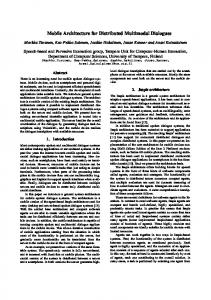
and which allows a sufficiently coherent set of processes to be gathered in a single module. While such a notion is clearly not new, the identification of the nature of the basic modules constituting the multimodal interface, and of the interactions between them, has been a crucial step in the project. A second driving force behind this architecture is that all operations within the dialogue management layer should be performed on a common meaning representation which is independent of both the application and any specific mode. To this end, all input from the modes to the dialogue management is cast in the common meaning representation, as is any output to the modes. Since one objective of the project is to develop a toolkit based on the architecture portable between applications, communication between the dialogue management and the application must be in the language of the application. To this end, dialogue management contains a module which maps the common meaning representation onto the application language. The resulting architecture is illustrated in Figure 1 below.
Graphics & Gesture Experts
Natural Language Experts
Dialogue Context Expert
Interface Expert Semantic Expert
Presentation
Dialogue Controller
User Modelling Expert
Communication Planning Expert
Formal Domain Expert
Informal Domain Expert
Dialogue Management
CMR Application KBS
Figure 1: Architecture for the first MMI2 demonstrator
2
Venaco 2nd Multi-Modal Workshop ‘91
The major functionalities of each of the expert modules can be described as follows: The dialogue controller deals with: the major control loop to manage the structure of the dialogue; activating whatever experts are necessary to support dialogue function; providing a theorem prover for CMR formulae; simple existential presupposition checking on CMR formulae; anaphora and deixis resolution. The dialogue context expert manages everything which has to do with recording the dialogue structure and extracting relevant information from it. The user modelling expert extracts user beliefs and preferences from CMR formulae; stores the user model provides access to the user model. The informal domain expert is responsible for storing plans for the domain task evaluating informal aspects of the dialogue. The communication planning expert is responsible for constructing the logical form of system output selecting the output mode. The formal domain expert is responsible for translating the CMR into domain terms representing metaknowledge of the domain. The interface expert is responsible for translating the CMR into interface terms the current physical layout of the interface. The semantic expert has all the knowledge about the intentional definitions of predicates used in the CMR. In the mode layer the various mode experts are responsible for input and output of each mode to/from CMR. In the application layer the NEST application designs computer networks. The following sections further discuss some basic aspects of the main modules enumerated above. But, in order to provide a practical context, we first start with some words about the application chosen as the testbed for the project. TESTBED APPLICATION: AN EXPERT SYSTEM IN COMPUTER NETWORK DESIGN An application has been developed within the project to act as a testbed for the multimodal interface. The requirements behind the choice of application were that it should be a domain where humans would perform the task using diagrams and language, and the dialogue would be sufficiently complex to be interesting. A practical requirement was also that the system developed should be commercially viable as a tool to those participating on the project. The domain of computer network design met these requirements and was chosen. In the development of the application, knowledge acquisition was conducted by watching and recording experts and clients designing networks; by collecting documentation on prior cases; by interviewing experts and clients who explained and justified recorded cases, and by performing Wizard of Oz experiments. These provided not only knowledge about the domain itself to by used in developing the application KBS but also sets of interview transcripts with associated documentation, and graphics, which could be used to analyse the dialogue structure; instances of multimodal communication to be used for evaluation; and assumptions and reasoning about the users to be used in the user model (see Falzon, this volume for a more detailed account of the studies of experts and clients). The application which resulted uses a frame architecture with constraints on the slots for objects in the design, which is then performed as a hierarchical task based on an initial skeleton (Darses, 1991). A general scenario for the task is that clients will firstly describe some requirements of a network; the expert will then elicit more detailed requirements; then an initial design will be produced; the client will then investigate this design and suggest modifications to both the design and the requirements; a new design will be produced and investigated. This cycle may be repeated several times. The design requirements include several essential requirements such as a detailed de3
Venaco 2nd Multi-Modal Workshop ‘91
scription of the geographical layout of the target building; descriptions of the number of machines to be included; the costs of most components and labour; a budget; and the load expected on parts of the system. There are also optional requirements such as the presence of any environmental hazards such as magnetic fields. Once the design has been performed, there are several types of analysis performed on it by the users; these include cost and the extensibility of the network. It is possible to design a network on the basis of essential requirements without being able to perform all the expected analyses. When these are required, they have their own requirements which must be elicited (such as the cost or exact type of some specific items). Therefore the dialogue does not just follow a simple structure of requirements elicitation from the expert, followed by design and user lead analysis. After the design there are system lead parts of the analysis, and the opening of most dialogues is user lead with the expert taking a passive role. Since the requirements include a building layout and locations of machines there is clearly scope for a graphical mode to be used as well as natural language to gain requirements and display designs. Business graphics are also used to display the results of the analyses. Experts and clients also draw various design symbols on diagrams while discussing potential network designs which were used as the basis for the set of gestures to be used in gesture mode. MODE INTEGRATION AND DIALOGUE CONTEXT MANAGEMENT The MMI2 architecture is based on the fundamental assumption that: mode integration should mainly be achieved by an integrated management of a single generalised discourse context. The core of the design is that any interaction, or any “discourse” between the user and the interface, in any of the modes, takes place in a common discourse world (which may be, but is not necessarily, connected to the real world, or to an application). Any entity mentioned in the course of an interaction acquires, by the sole virtue of having been mentioned, an existence in this discourse world, where it shall be called a discourse referent. Various operations may apply to discourse referents. They may be introduced (or created, or brought into the discourse) or referred to by using a description of a referent. Although they may be removed from the model theory of the CMR by being deleted from the application, they will remain within the discourse world. They may also be brought in or out of focus, and different sorts of foci can be distinguished. These notions are familiar to those working on Natural Language Processing. What we argue is that they are common to other modes as well, and are the most natural way to perform mode integration. Let us give a few examples about each of the modes. In natural language new discourse referents are typically introduced by indefinite noun phrases and referred to by definite noun phrases (many special cases can be found in the literature, but will not be discussed here). Thus, in: User (EM): Add a server to the network. Connect the server to... the indefinite expression “a server” will cause the introduction of a new discourse referent in the discourse world, and this referent will receive a unique identifier. The expression “this server” can then refer to the newly introduced discourse referent, and can possibly bring it into focus. For NL interaction, the referencing operation is done mainly through the use of descriptions which take the form of (definite) noun phrases. The basic problem is to relate such descriptions to unique referent identifiers: this process is usually known as “noun phrase resolution”. In the graphical or gesture mode, any basic graphical operation will have an effect on discourse referents. Creating a graphical object will obviously introduce a new referent. Selecting an operation with the mouse will perform a reference to an existing referent. Moving a graphical object will bring the corresponding discourse referent into focus. Changing the graphical display (zooming, displaying another network, selecting another window where
4
Venaco 2nd Multi-Modal Workshop ‘91
something else is displayed) would bring a different set of discourse referents into focus. For the graphical mode the referencing operation is done by selection: the referent has a graphical description (as it could have one or several NL descriptions) and selecting the graphical description leads to the identification of the new referent. The problem of identifying the referent selected is trivial since each graphical object should have as an associated property the identifier of the unique referent it represents. This association is easy to maintain: when a graphical object is created, it is either to display an existing referent (in which case the referent identifier is known) or to create a new one, in which case a new referent identifier name should be created automatically by the system. In the gesture mode, all operations are performed over windows which contain a display either graphical or textual. The gesture will contain the command to be performed, and the arguments to that command will be the object displayed in the window below the gesture, at exact screen co-ordinates with a fixed relationship to the gesture. If the display is graphical, the gesture mode will ask the graphics mode for the identity of the object at those co-ordinates. Since the command is known, the semantic selection restrictions on referents are also known. Therefore is there are multiple candidates for the graphical object at that location, those which do not meet the restrictions can be rejected. If the display is showing text, then an object will be created with a referent, and the content of the object will be the string of text beneath the gesture. In the command language mode, finally, basic operations on discourse referents are easy to identify, and are similar to graphical ones. Thus a command to add an object will create a discourse referent for that object; commands performed on objects will tend to bring the object into focus. Reference to existing discourse referents can be done by using the unique identifier to a referent as a parameter to a command. The referencing operation for command language is also simple, as the referent identifier itself can serve as the description of the referent. Reasoning in terms of discourse referents and focus already provides for interesting mode integration, which goes further than the traditional ostensive graphical deixis (simply selecting something with the mouse and asking “what is this?”). Thus in a sequence like: System (GR): User (NL): What is the server? System (GR): the first (graphical) utterance will bring a new set of discourse referents into focus. The NL query will then attempt to resolve the noun phrase “the server” against the discourse context and the current focus. The response determination module of the dialogue controller would then decide of a mode (graphics) and an appropriate graphical “communication act” (highlighting) to provide the answer. We are thus lead to study the conditions governing creation, focusing, reference and destruction of discourse referents across the communication modes. A first attempt to organise the factors controlling these events is indicated in Table 1 below: Creation NL input
Focus
(ind.) noun phrases
sentence content &
Reference (def.) noun phrases
structure
Graphics
Command
copy, paste, draw
COPY, CREATE
display, zoom
click
command content & structure
disourse ref. id
Table 1: Operations on Discourse Referents Across Modes
5
Venaco 2nd Multi-Modal Workshop ‘91
REPRESENTING INTERACTION: THE COMMON MEANING REPRESENTATION The second source of integration arises from the fact that many interactions can be expressed equivalently (from the point of view of meaning, if not ease of expression) in several modes, as the following examples illustrate: User (EM): User (GR): User (GS):
Suppress the Sun3 connected to the server Ella
User (EM): Augment the disk size of Ella by 100% User (GR): User (EM): User (GR): User (GS):
Suppress the blue servers (Colour on screen) Click on icons and select delete option
User (EM): User (GR):
Add a Sparc SLC in Room3
Although expressed differently, all these inputs must have the same effect on the application (knowledge based system) and on the dialogue context. Thus one of the results of MMI2 is to establish a taxonomy of actions across modes (e.g. the verb “surpress”, a DELETE option in a menu, a DELETE command or a gesture of crossing out something with the mouse all refer to the “deleting” operation). But integrating the representation of interactions across modes can go further than that. A second basic principle of the MMI2 architecture is that: there is a meaning representation formalism, common to all modes, which is used as a vehicle for internal communication of the semantic content of interactions inside the interface and also used as a support for semantic and pragmatic reasoning. This meaning representation formalism is called the CMR. The purpose of the CMR is to represent the meaning of interactions between the system and the user, or the user and the system. Such interactions are called “communication actions”. In MMI2 a communication action is a graphical action, a command language/gesture action, or a natural language action, which can be performed by either the user or the system. When the communication action is expressed in a natural language, the action is an utterance. The proposition expressed by a communication action consists of content and logical form. Following many other practical natural language systems we have chosen to express the logical component of the proposition in a language based on first order typed predicate logic where relations, and events as well as objects are reified (after Hobbs, 1985). To improve computational efficiency, reified relation predicates are normally represented in a binary form in CMR formulae, but the cases of relations are not given meaningful names, merely place markers relating to the intensional definitions in the semantic expert. Although our approach to representing meaning can be recognised as logical, we recognise that there are aspects of communication which are difficult, perhaps impossible, to capture in a purely logical approach. Therefore we have decided to include extra information in CMR concerning utterance type (declarative, interrogative, imperative, noun-phrase), enunciation conditions (temporal and aspectual), some syntactic information, and other information which we call annotations. So a CMR expression contains four sorts of information: utterance
6
Venaco 2nd Multi-Modal Workshop ‘91
type, annotations, logical formula, syntactic information. A CMR expression is part of a larger data structure the CMR_act. Since the natural language modes cannot always uniquely disambiguate input, several CMR expressions can be produced for one input, with one expression for each ambiguous interpretation of the input. These are listed together in the CMR Act. The CMR Act is itself part of a larger data structure, the CMR packet. This can contain multiple CMR Acts (one for each utterance in a multiple utterance discourse), details of the processing status (ok or Error), mistakes which have arisen in the processing if its status is Error (e.g. selection restriction violations on predicates in the logical formula), the mode of expression of the CMR packet, and the time at which the CMR packet was created. The following figure illustrates one example CMR representation. Although we shall not describe it in more detail here, the full definition of the CMR language has been completed and is available.
User input: What do the computers on the network cost? CMR( [ CMR_act_analysis( u_type(wh([x1]),question_mark), [ CMR_exp( [ anno(x2,[singular,definite,neuter]), anno(x3,[plural,definite,neuter]), anno(x1,[indefinite,singular])], description(desc(E,x2,LAN,true), description(desc(E,x3,COMPUTER, description(desc(E,x5,IS_ON,true), conj( [ atom(PRESENT,[var(x5)]), atom(ARG1,[var(x5),var(x3)]), atom(ARG2,[var(x5),var(x2)])]))), description(desc(null,x1,COST,true), description(desc(E,x4,COSTING,true), conj( [ atom(PRESENT,[var(x4)]), atom(ARG2,[var(x4),var(x1)]), atom(ARG1,[var(x4),var(x3)])]))))), nil)], nil)] ok, English, time(51,42,20,11,07,1991)) Figure 2: Example of a CMR representation.
7
Venaco 2nd Multi-Modal Workshop ‘91
DIALOGUE FLEXIBILITY AND DIALOGUE CONTROL The application, being a knowledge based system (KBS), has its own data and knowledge structures. Typically for a KBS, the specification of the problem may require a set of information of different types. If the dialogue is application-driven, the user will be asked for this information in a systematic order. But in a real problem acquisition dialogue, the user may shift topics, answer questions by other questions, provide ambiguous or incomplete answers that will require subdialogues, request help, or even change his mind. It is obviously the job of the interface, not the application, to deal with such problems. If the user-provided data were sent directly to the application they might well be in the wrong order or provide wrong values that would have to be corrected later. We have thus decided that, for reasons of flexibility, there should be a level of representation of the problem in the interface itself. This kind of problem has started to interest researchers in dialogue management and has been discussed notably by Julien at al. (1989), who illustrate it with an example taken from the a financial advisor system: System: How much do you want to invest in an emergency plan? User: Let us talk about my car loan instead! In the face of such an answer, the interface must either enforce a strict dialogue schema, or accept a shift in the topic, which supposes that is should be able to detect it, and to remember to come back later to the “emergency plan” topic if this one is essential for the formulation of the problem. To implement this kind of behaviour we have decided to implement an interface with four basic kinds of data structures: a desire stack, communication plans, task plans, and a discourse referent space. The first being inspired by Bunt (1989), and the second and third being inspired by Julien et al. (1989). These are locate within the architecture in the Dialogue Controller (DC), Communication Planning Expert (CP), Informal Domain Expert (IDE), and Dialogue Context Expert (CE) respectively. The basic role of the space of discourse referents has been described before. The desire stack in the DC is the basis of the main control loop. The CMR of a user’s utterance will include the utterance type when it is passed on from the input mode. This is the highest level of illocutionary description which the NL systems can be assured of producing (declarative, interrogative, imperative, noun-phrase). These directly map onto user desires; if the utterance type is interrogative, then the User Wants to Know something (UwK); if the utterance type is imperative then the User Wants something (Uw); where the object of the desire is represented by the formula of the CMR. These user desires are passed to the IDE for informal evaluation. The process of informal evaluation consists of matching the formula of the CMR against a task plan to check if the preconditions on the task plan are met. If they are not, then the system has a desire to meet them. For example, if the user wishes to know the cost of the machines on the network (as in the CMR in Figure 3), then the task plan for cost will be accessed. This requires that the exact type of each machine is known. If a machine is known as a Sun or a Vax rather than a particular model, then the cost cannot be determined. In this case the informal evaluation will result in desires being added to the desire stack stating that the System Wants to Know (SwK) the exact model of the computers. Since these will be placed on the top of the stack, these desires will then be executed. The form of execution for desires of the SwK type, is to ask the user a question. Therefore the CP is called to find the best way of expressing the question by finding the appropriate communication plan. When the user answers the question, the IDE will find all the preconditions on the task plan are met, and the CMR requesting the cost of computers passes the informal evaluation. It can then be formally evaluated against the Formal Domain Expert, which queries the application, determines an answer, calls the CP to express the answer, which is then presented to the user. This control structure of a desire stack using informal evaluation against task plans, formal evaluation and communication planning allows for great flexibility in the dialogue. If the system asks a question (e.g. what is the location of a computer?) and the user replies by 8
Venaco 2nd Multi-Modal Workshop ‘91
asking a question, then the system desire (SwK the locations) will stay on the stack until the users desire has been satisfied. If in this processing the locations are identified, then when the system desire is eventually encountered on the top of the stack, the user will not be asked the question. It is a generalisation to refer to formal evaluation as only being against the application. Formal evaluation can be against any of three model theories in the present system. One of these is indeed the application, the other two rest in the interface expert and the command language mode. The command language theory is very small and just defines some simple operations such as aliasing command names. The model theory for the interface semantics is more complex, and supports some aspects of multimodal dialogue. For example, the user can make an explicit request for the answer to a question to be presented in a specific graphical representation, as in 38 & 39: 38 user (EM): 39 system (EM): 40 user (EM): 41 system (EM):
Display a bar-graph of the cost of the computers. ok Display that as a pie chart. ok
where the command to display a bar-graph refers to an interface concept rather than a domain concept, although the query concerning cost clearly refers to domain concepts. In such cases within the same formula some atomic predicates are evaluated against the model theory of the domain whereas others are evaluated against the model theory of interface objects (DISPLAY, BAR-CHART). An extension of this requires the identification of a graphical referent used in a natural language utterance, followed by the domain query and the explicit interface theory assertion again, as in 40 & 41. A similar example arises with the expression of spatial relationships in natural language, e.g.: 86 user (EM): 87 system (EM):
What is the type of the box on the left of the server? RETIX_2265
where the relationship expressed by “on the left of” is defined in the interface theory whereas other relationships are defined in the domain theory. Such examples are discussed further later in the context of the mode layer of the architecture. USER MODELLING In MMI2, the role of the user modelling module is to provide the information which results in an increase in the cooperativity of the system. The user modelling expert builds up, and maintains the user model. The user model is the knowledge source in the system that contains explicit assumptions on all aspects of the user that may be relevant to the behaviour of the system. User models will be stored between sessions as User Profiles which will be downloaded for experienced users at logon. The major uses of the information in the user model are for: 1) The Dialogue Context Expert to identify speech acts, ellipsis and other pragmatic features on the basis of the user’s goals and beliefs. 2) The Mode Experts to present information using the symbols, lexical items and style the user prefers. 3) The Informal Domain Expert will use the user’s current goal to identify the user’s current plan and Communication Planning Expert uses this to provide cooperative responses. Responses will also be tailored on the basis of the user’s beliefs according to Grice’s (1975) maxims to avoid redundancy and to emphasise and explain the user’s misconceptions. 4) The Domain Expert will use items of user specific information in completing do9
Venaco 2nd Multi-Modal Workshop ‘91
main plans which will form queries to the knowledge based system. The information stored about the user may be acquired or updated in three ways by the User Modelling Expert: 1) the model is predefined by the project team. A hierarchy of stereotypical models include established information about predetermined classes of users. Users will inherit class based information from these stereotypes. Users may change their classes during system use and the inherited information will be updated. 2) the model is explicitly modified - i.e., the user is questioned about his/her preferences, knowledge etc. 3) the modification is achieved implicitly - i.e., rules in the user modelling expert are used to derive the user’s knowledge and preferences from the record of their interaction in the Dialogue Context Expert, Dialogue Controller and Domain Expert. The basic framework of the user modelling component comes from General User Modelling System - GUMS of Finin and Drager (1986). This provides four essential features of the user model itself: 1) An interface between the user model and the rest of the system; 2) A mechanism for overidable default inheritance from stereotypes with optional negation as failure; 3) A truth maintenance mechanism to manage the updating of inheritance from different superordinate classes during a session as the user’s membership of a class changes; 4) A mechanism for storing user and class models between sessions. Two advances on the GUMS model are required for the underlying framework of the user modelling component in the MMI2 architecture. Firstly, the GUMS model only supports inheritance from a single stereotype which is limiting since users could be both a member of a class with knowledge about the domain, and another with knowledge about the interface and system itself. Inheritance from multiple stereotypes has been added to the GUMS system. Multiple inheritance brings with it the possibility of conflicts between information in different stereotypes. These are handled by searching for certain information rather than just default values; if these conflict then the certain information overrides the default. Similarly, where negation as failure is used to show the lack of knowledge or belief, and knowledge or belief is stated, then the presence of knowledge or belief is returned. Where certain but contradictory knowledge is stated in different places, an temporary unsatisfactory heuristic is applied that the first version encountered in the bottom up breadth first search is returned. The second change follows from the use of multiple stereotypes. Sparck Jones (1987) succinctly illustrates the problems with assuming that the user of the system who is entering the commands is actually the user of the system for both the interface and the reasoning components of the system. Her potent example is one of a social welfare worker entering information on behalf of a client where the views of the user act as a filter on the information obtained about the client; either approving or otherwise. To overcome this complexity, the leaf node of the user model in the present system represents the combination of the user and the client. Therefore this user model inherits from both the user and the client nodes in the lattice, each in turn inherit from other stereotypically defined nodes. A major requirement of the MMI2 system is to produce co-operative responses for the user. This requires representations of the user’s goals; the plans for achieving them; the user’s beliefs; an evaluation of whether they are correct knowledge or misconceptions with respect to the systems view of the world which is assumed to be true; some decision relevant information to be used in task plans for the KBS application; and various attitudes and preferences of the user for explanation style, lexical item choice, and interface style and options. The user’s beliefs are stored in the prototypes and the user’s own model. These can be acquired explicitly or implicitly as suggested above. The rules for implicitly acquiring user beliefs follow those used by Kass (1988). In order to use user beliefs to interpret input to the interface or to tailor output for the user it is useful to identify the beliefs as true to the world, and therefore user knowledge, or false in the world, and therefore misconceptions. The test of truth in the world is made by comparing the user’s beliefs with information held in the Domain Expert and the Semantic
10
Venaco 2nd Multi-Modal Workshop ‘91
Expert. A set of rules exist to compare beliefs with the representations in the other experts and change their status if a judgement can be made. If no comparison is possible the beliefs remain beliefs and are not classified as knowledge or misconception. The basic user model architecture allows many stereotypical models to be introduced representing domain and user based distinctions. However it does not specify the user classes or stereotypes for a particular domain or system; the rules for determining if a user is at any time a member of a particular class; the information which the class stereotype should contain about the user which should be inherited by that user; or any classification of the information which should be held about users or stereotypes. The set of classes and rules for determining if users belong to them, along with the sets of possible relevant goals, preferences, decision relevant information, knowledge and beliefs which must be included in this architecture were established from data collected during the knowledge acquisition and Wizard of Oz studies of experts and users (Cahour, 1989). THE MODE LAYER The mode layer of the MMI2 is illustrated in Figure 3. This shows that the DC communicates with the Interface Expert (IE) through CMR packets. The role of the IE here is simply to provide a buffer to store system output and deal it out to the relevant mode when it is available; or to store user input until the DC is ready to read it. User input is received by the IE in the form of CMR packets from the Command Language mode (CL), Natural Language mode (NL), Gesture mode or graphics mode through the Graphics Manager. System output can be passed to either the NL or graphics modes, the CL and Gesture modes are not used for system output. USER window manager (SunView / X-windows)
table tool
Gesture Mode graph network hierarchy chart tool tool tool tool Graphics Manager
CL
NL text tool
CL
NL
Mode
Mode
Interface Expert CMR Dialogue Controller Figure 3: The architecture of the MMI2 mode layer
11
User Modelling Expert
Venaco 2nd Multi-Modal Workshop ‘91
The CL and NL modes both translate user input into CMR. The NL mode also translates CMR into natural language. In both cases the user directly interacts with a simple text editor style input tool which stores the user’s input until a carriage return is pressed before passing it to the mode. Similarly, the tool formats system output and presents it once the NL mode has produced natural language strings. The natural language systems used in MMI2 will not be discussed in detail here (see Binot et al., 1990). The English system used is BIM-LOQUI which was developed prior to the present project and incorporated into it with little change (see Ostler, 1989; Binot et al., 1988). The French (Dami and Lallich-Boidin, 1991) and Spanish (Ruiz, 1991) systems have been developed within the project. The three systems do not all use the same approach to parsing or semantic generation, showing that the underlying CMR is not only applicable across modes, but also across approaches to natural language processing. Graphical interaction is handled in two layers. The outer layer consists of a series of interactive tools which visualise information using different conventions. Each of these individual tools has its own data structures which must be created from the CMR by the Graphics Manager layer below them. The Gesture mode operates by catching the events from the mouse on the windows of any of the graphical tools when the user has selected gesture as the mode to use from the menu on a tool. The gesture mode recognises hand drawn gestures (such as editing symbols) by correlating the pattern of features in the event stream with a prestored library of up to 50 gestures for each application. Neither a larger library, nor a neural net approach (see Pittman, 1991) are used since gesture is not the only mode of interaction and is only used when it is most convenient. Studies of potential users have shown that this set size is sufficient for the applications investigated. Once a gesture is recognised, the arguments to the gesture (e.g. MOVE with arguments Machine1 and Room2) are requested from the tool on which the gesture was drawn using the screen co-ordinates of each argument and the semantic selection restrictions on the argument as cues. The graphics manager translates CMR into the data structures required by each of the graphics tools, and translates the output from the graphics tools produced when the user acts on them into CMR. The CP decides which mode to use to present information to the user on the basis of the effectiveness and efficiency of a mode to convey the information or request. When the graphics mode is chosen, the graphics manager must then decide which graphics tool to use to visualise the information and convert the logical CMR representation into that required for the chosen tool (following Mackinlay, 1986). The tools so far available allow information to be presented as building or network diagrams, as pie charts, histograms, tables, line graphs or scatterplots, or as hierarchies. These visualisation tools all allow the presentation of information but also allow the user to directly manipulate the representations; for example, users can move the values shown on bar charts to produce CMR packets which are sent to the DC to alter the state of the KBS. The main aims of the Network Diagram Tool are: To allow users to draw buildings and networks either by free hand drawing or by means of graphical tools described below. In the first version, we decided to restrict the drawing to only one building with only one floor. The user can draw separately a building and a network which will be represented by two distinct planar maps (Ben Amara, et al., 1991). However, we must establish some links between buildings and networks: for example, a machine is inside one room, a cable skirts around walls, etc.... For this purpose, we have developed some functions which attach attributes to the data structures. To make the pre-processing of the drawing (sampling, adjusting, erasure elimination) To deduce the semantics of drawings from the planar map data structures. To develop some functions allowing communication between Network Diagram and the other modules (for example: to move a machine from one room to another, using either natural language or command language or gesture). The core set of operations which can be performed on the graphical tools are to select,
12
Venaco 2nd Multi-Modal Workshop ‘91
move, add and delete objects. These operations can be performed by the user on the graphics tools and by the graphics manager on a tool. The tool which displays computer networks also allows the objects to be linked together, have links removed, and the identity of all the objects, or of the object at a specific location queried by the system. The graph and table tools also allow the values of objects to be set by the user and the system. This set of operations is sufficient to allow the logical CMR from the DC to be converted into actions on the tools by the Graphics Manager, and for the user actions to be recoded as a series of terms in CMR formulae. The variables used for objects in the graphics tools are different from those used in the CMR so a table is maintained in the Graphics Manager to map between these.
Pie Chart
Histogram Table
Computer Network
Line Graph
Natural Language
Command Language Figure 4: A typical screen display of MMI2in use.
Users can perform actions in each tool which: select menus; are interpreted as gestures; act to change the appearance of the tool used (e.g. changing the fillings of graph bars or other presentation features); or which are communication actions that must be encoded in CMR for the dialogue management system. Actions which are not communication actions do not result in CMR since they are not communicating with the KBS. However, they do result in changes to the UM which stores such preferences. In these cases direct calls are made to the UM to store that a preference for a particular presentation style is preferred by that user for that class of visualisation within the task being performed. Whenever a graphical tool presents
13
Venaco 2nd Multi-Modal Workshop ‘91
information the Graphics Manager always reads the UM to determine the relevant preferences, which will either be those set by the user explicitly, or those inherited from a stereotype to which the user belongs. Communication actions include the selection of an item as a referent for a natural or command language operation, or the explicit creation or adjustment of information presented; for example, a user may type the natural language command “move [select] this workstation [select] here.” or the request “What is the disk capacity of [multiple selection] these”. When users make communication actions the graphics manager will construct a CMR representation for the action and pass it to the DC, this may result in the DC returning a CMR packet to be displayed. Similarly, users can ask for information in another mode which may result in a CMR packet being sent to the Graphics Manager for graphical presentation. In either case, when the Graphics Manager receives a CMR packet from the DC it will decide if it can be displayed as network diagram, hierarchy or graph (it is intended to also include tools to present set relationships using Venn diagrams although this is not yet implemented). The Graphics Manager will then dynamically design the data structure for the chosen visualisation tool, and then call that tool to render the image. If none of these, it determines if it can be represented as a change in the state of an existing representation. If it is unable to determine a way of presenting the information it will return the CMR packet to the DC with amendments as to why it failed to present it. This will result in the DC choosing another mode to present the information. The details of the design method are too lengthy to describe here, although they are available from the authors. In addition to translating user actions on the graphical tools into CMR and presenting CMR through the graphical tools, the third role of the graphics manager is to support the use of graphical referents and descriptions in natural language. Each of these forms of reference is ultimately resolved by the processes used to resolve reference in natural language. Three classes of support are offered which enable the interaction of modes by constraining the set of possible referents in the natural language component. Firstly, non-ostensive deixis - the indication of a natural language referent in the context of the utterance without pointing, e.g. “move the fileserver” where there may be two but only one is shown on the screen (this would be anaphoric reference if it were not visible on the screen but had been mentioned in the dialogue). Non-ostensive deixis is resolved in MMI2 by the Graphics Expert constantly updating a list of possible discourse referents which are visible on the screen in CMR terms. This is used by the DC to disambiguate whether a textual referent should be chosen from its list of previously mentioned textual referents (anaphoric referents), or the current list of possible non-ostensive deictic referents. The DC has direct access to this list at all times. Secondly, reference in natural language to objects by their graphical features. The resolution of referents from definite descriptions of domain objects by their graphical features requires that the graphical features of objects be available to the natural language referent resolution mechanism as well as the real world features. For example, in a discourse about the performance of local area network which is displayed diagrammatically, one workstation is shown as a purple icon. A user intending to remove this machine from the network could type any of: 175 user (EM): remove the Stellar workstation 178 user (EM): remove the purple workstation 181 user (EM): remove the purple icon. All of these use natural language descriptions of the intended item. The first uses a domain description, and the third uses a graphical description. The second is ambiguous as to whether the workstation in the world is purple or the icon representing the workstation is purple. All of these require processes which identify linguistic referents to operate, but the second two require that those processes have access to descriptions of the graphical representation of the domain objects. Thirdly, natural language references to graphical spatial relationships. This is an extension of the previous problem where the definite reference is not merely in terms of the graphical description of the object but includes spatial relationships in the graphical display. In the same example of a displayed network, the user could ask to “remove the top workstation” or “remove 14
Venaco 2nd Multi-Modal Workshop ‘91
the left workstation”. In both these cases the spatial relation is ambiguously one in the domain or in the graphical representation. For example, “the top workstation” could be that on the uppermost floor of the building or that on the upper edge of the displayed diagram. This ambiguity must be resolved by the processes which identify linguistic referents using the context of the utterance, or by asking the user to disambiguate the example explicitly. However, in order to appreciate the ambiguity these processes must have access to a representation of the spatial geometry of the domain and of the user’s perception of the machine representation. It is intended to address both of these issues in the MMI2 project although no resolution is currently available. Both problems could be overcome if users identified referents by selecting graphical representations with the mouse, but this may not be the preferred method. As with other aspects of “naturalness” in the interface, this will require studies of users performance preferences as these systems develop. A further description of these issues is given in (Wilson and Conway, 1991). CONCLUSIONS We have presented what should probably be considered an ambitious architecture for a multimodal interface system, including concerns such as user modelling, communication planning, multimodal meaning representation, dialogue context management, etc. All the mentioned features are not yet and probably will not be developed to the same degree of completeness. The knowledge in the application, user model, communication plans and other data structures was all acquired from studies of real experts and potential users through Wizard of Oz studies using MUSK (Crampton, 1987) to mediate and record data. We have therefore taken the pragmatic approach of populating the architecture with the knowledge required for users in this domain rather than developing theoretically complete rule sets. Although this enables us to demonstrate the architecture it makes it hard to evaluate the wider impact of the system. The examples given in this paper are all performed by the system and come from a 160 line demonstration script derived from the human transcripts. We are not yet able to estimate the effort required to populate the system for a new domain or to judge the balance between generic and domain specific rules and knowledge in these knowledge sources. However, we see the architecture itself, which we have tried to describe in a clean and modular way, as a step towards a reference framework for further research and implementation work on these topics. REFERENCES Ben Amara, H., Peroche, B., Chappel, H., Wilson, M.D. (in press) Graphical Interaction in a Multi-Modal Interface. In Proceedings of Esprit ‘91 Conference, Kluwer Academic Publishers: Dordrecht. Binot, J-L., Demoen, B., Hanne, K.H., Solomon, L., Vassilou, Y., von Hahn, W., Wachtel, T., (1988) LOKI: A Logic Oriented approach to data and Knowledge bases supporting natural language Interaction, In Proceedings of the Esprit ‘88 Conference, North-Holland: Netherlands. Binot, J-L., Falzon, P., Perez, R., Peroche, B., Sheehy, N., Rouault, J. and Wilson, M.D. (1990). Architecture of a multimodal dialogue interface for knowledge-based systems. In Proceedings of Esprit ‘90 Conference, 412-433. Kluwer Academic Publishers: Dordrecht. Bunt, H.C., (1989) Information Dialogues as Communicative Actions in Relation to Partner Modelling and Information Processing. In M.M. Taylor, F. Neel & D.G. Bouwhuis (Eds.), The Structure of Multimodal Dialogue, North-Holland: Netherlands. Cahour, B. (1989) Pragmatic Modelling in consultation dialogues, Proceedings of the Work With Display Units Second Conference, Montreal, 11-14 Sept., 1989. Elsevier: Amsterdam. Crampton, C. M. (1987). MUSK - A Multi-User Sketch Program, In Proceedings of
15
Venaco 2nd Multi-Modal Workshop ‘91
the EUUG Conference, Dublin 1987. Dami, S., Lallich-Boidin, G., (1991) “An expert-system for french analysis within a multimode dialogue to be connected”, 23 p., RIAO 91 conference, Barcelona. Darses, F. (1991) Constraints in Design: Towards a methodology of Psychological Analysis based on AI formalisms. In D. Diaper et al. (Eds) Human-Computer Interaction: INTERACT ‘90, 135-139. Elsevier Science Publishers: Amsterdam. Duce, D.A., Gomes, M.R., Hopgood, F.R.A. and Lee, J.R. (1991) User Interface Management and Design, Eurographic Seminar Series, Springer-Verlag: Berlin. Falzon, P. (this volume), Analysis of multimodal dialogue for domain, explanation and argumentation knowledge. Finin T. and Drager D. (1986). “GUMS: A General User Modelling System.” Technical Report MS-CIS-86-35, Department of Computer and Information Science, University of Pennsylvania. Grice, H.P. (1975) Logic and Conversation. In P. Cole and J.L. Morgan (Eds.) Syntax and Semantics, volume 3, pages 64-75. Academic Press, New York. Hobbs, J.R. (1985) Ontological Promiscuity. In Proceedings of the 23rd Annual Meeting of the Association for Computational Linguistics, Chicago, June 1985, 61-69. Kass, R.J. (1988). “Acquiring a Model of the User’s Beliefs from a Co-operative advisory Dialog.” Technical Report MS-CIS-88-104, Department of Computer and Information Science, University of Pennsylvania. Mackinlay, J. (1986) Automating the Design of Graphical Presentations of Relational Information, ACM Transactions on Graphics, 5(2), 110-141. Ostler, N.D.M, (1989) LOQUI: How Flexible can a formal prototype be? In M.M. Taylor, F. Neel & D.G. Bouwhuis (Eds.), The Structure of Multimodal Dialogue, North-Holland: Netherlands. Pfaff, G.E, (1985) User Interface Management Systems, Eurographic Seminar Series, Springer-Verlag: Berlin. Pittman, J.A. (1991) Recognising Handwritten Text, in Human Factors in Computer Systems, Proceedings of ACM CHI ‘91, pp 271-276. Perez Ricard y Barreras Joan (1991) “Un experto semantico para un interfaz multimodal” Articulo presentado al VII Congreso de la SEPLN (Valencia 1991). Ruiz Anton, J.C. (1991) “Un parser basado en la sintaxis de dependencias”. Procesamiento del Lenguaje Natural, 9, pp. 169-176. Sparck Jones K. (1987) Realism about User Modelling. Technical Report no. 111, University of Cambridge Computer Laboratory. Wilson, M.D., and Conway, A. (1991) Enhanced Interaction Styles for User Interfaces, IEEE Computer Graphics and Applications, vol 11, pp 79-90.
16