Connecting Brains to Robots: An Arti cial Body for Studying the Computational Properties of Neural Tissues
Abstract We have created a hybrid neuro-robotic system that establishes two-way communication between the brain of a lamprey and a small mobile robot. The purpose of this system is to offer a new paradigm for investigating the behavioral, computational, and neurobiological mechanisms of sensory-motor learning in a unied context. The mobile robot acts as an articial body that delivers sensory information to the neural tissue and receives command signals from it. The sensory information encodes the intensity of light generated by a xed source. The closed-loop interaction between brain and robot generates autonomous behaviors whose features are strictly related to the structure and operation of the neural preparation. We provide a detailed description of the hybrid system, and we present experimental ndings on its performance. In particular, we found (a) that the hybrid system generates stable behaviors, (b) that different preparations display different but systematic responses to the presentation of an optical stimulus, and (c) that alteration of the sensory input leads to short- and long-term adaptive changes in the robot responses. The comparison of the behaviors generated by the lamprey’s brain stem with the behaviors generated by network models of the same neural system provides us with a new tool for investigating the computational properties of synaptic plasticity.
1
Bernard D. Reger1 Karen M. Fleming 1 Vittorio Sanguineti 2 Simon Alford3 Ferdinando A. Mussa-Ivaldi1 1
Department of Physiology Northwestern University Medical School Chicago, IL 60611.
[email protected] 2 Dipartimento di Informatica Sistemistica e Telematica Universit`a di Genova, Italy 3 Department of Biological Sciences University of Illinois at Chicago Chicago, IL 60607
Keywords plasticity, modeling, hybrid system
Introduction
Since its inception, robotic science has made great contributions to the study of motor learning and control in humans and other biological systems [14]. The most notable contribution has been the determination of what interesting computational problems must be solved by the brain as well as by an intelligent machine when either one must control the mechanical interaction between limbs and environment. Theories concerning what computational problems must be solved by an intelligent system have been called competence theories [15] to distinguish them from performance theories concerning the physical processes that are actually chosen to solve a problem. In this paper, we present a rst attempt to utilize a robotic system for investigating the neural processes underlying sensory-motor adaptation, that is, for understanding a distinctive feature in the performance of biological systems. Our goal is to develop a c 2001 Massachusetts Institute of Technology °
Articial Life 6: 307–324 (2000 )
B. Reger, K. Fleming, V. Sanguineti, S. Alford, and F. Mussa-Ivaldi Connecting Brains to Robots STIMULUS
FROM LIGHT SENSORS
ISOLATOR
VARIABLE-FREQUENCY PULSE GENERATOR
nOMI SPIKE DETECTION
AMPLIFIER
nOMP PRRN
HIGH-PASS ARTIFACT RECTIFICATION FILTER CANCELLATION LOW-PASS FILTER
TO MOTOR ACTUATORS
KHEPERA MOBILE ROBOT
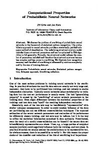
Figure 1. Block diagram of robot signal ow. The neuro-robotic interface (shaded center region) translates the light sensor data from the robot (right) into a stimulation pattern for the lamprey preparation (left). The neural response is converted into motor signals by the interface.
computational and experimental framework for relating the neurobiological study of neural plasticity—the modication of neuronal excitability following past experience of input and output patterns—to the behavioral functions that are supported by neural plasticity. The framework that we have developed is a hybrid system, which establishes a two-way signal exchange between a mobile robot and brain tissue maintained alive in vitro from the reticular formation of the lamprey—a primitive eel-like vertebrate. The reticular formation is a structure that combines central commands with sensory information of various origins—visual, tactile, vestibular, and so on—and modulates the motor output of the spinal cord. In our experimental arrangement, the brain and the robot are interconnected in a closed loop. They communicate through an interface that transforms (a) light information from the robot’s optical sensors into electrical stimuli to the lamprey’s brain stem, and (b ) recorded neural activity from two brain stem nuclei into motor commands to the robot’s wheels (Figure 1). We have chosen the lamprey for this rst study for a variety of reasons. First, the neural circuits of the lamprey’s spinal cord have become a prominent experimental model for studying the cellular basis for locomotion in vertebrates [12]. Second, recent studies have revealed that long-term changes of synaptic responses can be produced by specic stimulation patterns applied to reticular neurons in lampreys [2]. Last, but not least, the lamprey’s brain stem has two notable methodological advantages: (a) it can easily be maintained alive for extended periods of time by placing it in a refrigerated and oxygenated Ringer’s solution, and (b) it contains neurons—the M¨uller cells—that are particularly large, easy to identify, and easy to record from. From the standpoint of a neurobiologist, the neuro-robotic system can be regarded as a system for complementing the electrophysiological study of neuronal properties with an articial behavioral context. We must stress the adjective “articial,” because the signals that normally would travel along the circuits that we are stimulating are signals of vestibular rather than visual origin. Vestibular signals convey information about the orientation of the body with respect to the gravity eld. Under normal physiological conditions, lampreys use this information to maintain their posture aligned with the vertical axis. While visual signals have a different “meaning,” in our experimental arrangement they play a role similar to that of gravitational signals. In this brain stem preparation we have selected a portion of neural circuitry that in normal circumstances combines vestibular signals and motor commands to stabilize the orientation of the body during swimming [8, 9, 16, 18]. This system has 308
Articial Life Volume 6, Number 4
B. Reger, K. Fleming, V. Sanguineti, S. Alford, and F. Mussa-Ivaldi Connecting Brains to Robots
been shown to be adaptive, as unilateral lesions of the vestibular capsules are followed by a slow reconguration of neural activities until the correct postural control is recovered [6, 7]. In our hybrid system, vestibular signals are replaced by light intensity signals. As the vestibular signals have a right and a left source—the two vestibular capsules—so do the two light intensity signals originating from sensors on the right and the left side of the robot. Therefore, the natural stabilizing behavior, in which the lamprey would track the vertical axis, corresponds, in the hybrid system, to a positive phototaxis, that is, to a tendency of the robot to track a source of light. We are convinced that the properties of the information processing associated with natural behaviors may be explored by observing the information processing associated with the articial behavior. This, in a way, is a consequence of the abstract and generalized nature of information. An obvious advantage of our hybrid system, always from the point of view of experimental neurobiologists, is that, unlike natural motor behaviors, articial behaviors do not interfere mechanically with the electrophysiological setup. In any study involving intra- or extracellular recording, even the slightest motion of the tissue tends to cause unwanted displacements of the electrodes. From the perspective of neural computation, the hybrid system provides us with a means to test models of information processing by direct interaction with a biological neural network. As we detail in the methods section, the behavior of the robotic system is described by a relatively simple—and yet nonlinear—system of differential equations. To the extent that the brain properties may be considered stationary (over the time scale of robot movements ), the combination of brain and robot may be described as an autonomous system whose behaviors are shaped by the structure of the neural pathways and connections intervening between stimulating and recording electrodes. While the point of view of an engineer leads to the problem of designing systems that generate some pre-specied behavior, the perspective of a neuroscientist suggests the reciprocal problem of discovering the biological “design” that subserves the observable behaviors. In our work, we are taking this second perspective: the observation of the sensory-motor behaviors that emerge from the neuro-robotic system offer an insight into the computational structure of the neural system. Here, we report three initial ndings of this study. First, we have succeeded in obtaining stable behaviors over extended periods of time, characterized by repeatable motor responses to a light source. Second, in different preparations, we have observed different responses ranging from light tracking to light avoidance. Through simple simulations, we show how these different responses may be readily accounted for by different patterns of connectivity between stimulation and recorded signals. The neuro-robotic system allows us to substitute a mathematical model for the actual neural tissue and to compare their behaviors. This comparison provides an additional element for testing the validity of the model. Using this approach, we were able to establish that low-order polynomial representations of the input/output (I/O) transformation performed by the neural tissue is adequate to capture the main features of the robot’s movements. Higher-order approximations of the neural activities lead to a degraded performace. Thus, this method is useful in determining at what point the accurate representation of measured neural activities becomes effectively a form of overtting, that is, tting to the noise in the electrophysiological signal. Finally, we have observed some preliminary but consistent evidence of plastic changes in synaptic transmission following unilateral alterations of the sensory inputs from the robot. These ndings provide supporting evidence for the use of neuro-robotic systems in the study of the neurobiological mechanisms of sensory-motor learning and control. Articial Life Volume 6, Number 4
309
B. Reger, K. Fleming, V. Sanguineti, S. Alford, and F. Mussa-Ivaldi Connecting Brains to Robots
2
Methods
In this section we describe the components of the hybrid neuro-robotic system, the experimental setup used to assess its performance, and the basic computational model that characterizes the system’s behavior. 2.1 The Neural Preparation The neural component of the hybrid system is a portion of the brain stem of the sea lamprey in its larval state. In larvae of the sea lamprey Petromyzon marinus, anesthetized with tricane methanesulphonate (MS222, 100–200 mg/l), the whole brain was dissected and maintained in continuously superfused, oxygenated and refrigerated (9–11± C) Ringer’s solution (NaCl, 100.0 mM; KCl, 2.1 mM; CaCl2 , 2.6 mM; MgCl2 , 1.8 mM; glucose, 4.0 mM; NaHCO3 , 25.0 mM); details are in Alford et al. [2]. We recorded extracellularly the activity of neurons in a region of the reticular formation, a relay that connects different sensory systems (visual, vestibular, tactile) and central commands to the motor centers of the spinal cord. We placed two recording electrodes in the right and left posterior rhombencephalic reticular nuclei (PRRNs ). We also placed two unipolar tungsten stimulation electrodes among the axons of the intermediate and posterior octavomotor nuclei (nOMIs and nOMPs). These nuclei receive inputs from the vestibular capsule, and their axons form synapses with the rhombencephalic neurons on both sides. The impedance of the stimulation electrodes ranged between 1 and 2 MV. The recording electrodes were glass micropipettes lled with 1 M NaCl (1.5–10 MV impedance ). The recorded signals were acquired at 10 kHz by a data acquisition board (National Instruments PCI-MIO-16E4) on a Pentium II 200 MHz computer (Dell Computer Corp.). 2.2 Electrode Placement While the axons of the nOMI remain ipsilateral, those of the nOMP cross the midline. As a result, the activity of one vestibular capsule affects both the ipsi- and contralateral reticulospinal (RS) nuclei. We placed each stimulating electrode near the region in which the axons of the nOMI and nOMP cross (Figure 1). This placement of the electrodes also induced predominantly excitatory responses in the downstream neurons. The recording electrodes were placed on either side of the midline, near the visually identied neurons of the PRRN. To verify the placement of the stimulating electrodes, we delivered brief single stimulus pulses (200 m s) and observed the response in both the ipsi- and contralateral PRRN neurons. Once it was determined that the stimulation electrodes were properly placed, the recording electrodes were moved caudally in order to pick up population spikes. 2.3 Neural Input/Output Measurement After inserting the electrodes, we measured the I/O response of the neural preparation, dened as the dependence of the ring rates of both left and right PRRN neural populations on trains of stimuli at different frequencies. This is a macroscopic measure of the “computation” performed by the neural circuit under study, which determines the behavior of the neural-robotic system. We applied to both stimulating electrodes trains of ve pulses, whose frequencies stepped sequentially through all pairings of 1, 2, 5, 10, and 25 impulse per second (ips) values. Firing rates were determined using the same algorithm that was used to generate the control signals for the robot wheels. We repeated the application of each pair of test stimuli at least ve times, separated by a 20 s resting interval to prevent habituation. 310
Articial Life Volume 6, Number 4
B. Reger, K. Fleming, V. Sanguineti, S. Alford, and F. Mussa-Ivaldi Connecting Brains to Robots
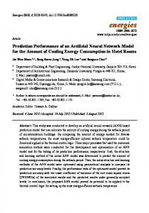
Figure 2. Robot setup. Using a pattern of colored disks (lower right), the overhead camera tracks the robot. Trajectories are plotted, each symbol representing a target light (upper right).
2.4 The Robot The robot system is the base Khepera module (K-Team ). Its small size allows us to use a small workspace (Figure 2). A circular wall was constructed with a 2 ft diameter and then painted black to reduce the amount of reected light. Placed along the circumference of the robot are eight sensors, each providing proximity and light intensity information. The sensors are located on opposite sides of the robot’s midline Articial Life Volume 6, Number 4
311
B. Reger, K. Fleming, V. Sanguineti, S. Alford, and F. Mussa-Ivaldi Connecting Brains to Robots
at 10± , 45± , 85± , and 165 ± from the front position. Two wheels provide a means of locomotion for the small robot. Our computer system communicates with the robot c application. Eight lights are through the serial port and a custom designed LabVIEW° ± mounted at the edge of the robot workspace at 45 intervals. The lights were numbered 1 through 8 counterclockwise with light 1 located at the rightmost position (0± ). The lights are computer controlled using the digital outputs of our acquisition card. These lights generate the stimuli that elicit a phototactic response. 2.5 The Interface The interface acts as an interpreter between the neural signals and the robot control system (Figure 1). It is responsible for transforming the robot’s light sensor information into vestibular inputs and then processing the neural activity of the reticulo-spinal nuclei in real time and translating it into motor commands for the robot. 2.5.1 Stimulus The light intensities detected by the robot sensors determine the frequencies at which the right and left vestibular pathways are stimulated. As stated above, there are eight light sensors on the robot. We weighted the sensors to give the greatest strength to sources of light that come at 45± and to ignore the rear sensors. The weighted sum of the sensors on each side is multiplied by a gain factor that determines the maximum stimulation frequency. The nal result is the frequency at which we stimulate each side. We use the digital counter on the acquisition board to generate a pulse train. This pulse train is delivered to the neural preparation by the tungsten electrodes after passing through ISO-Flex stimulus isolators. 2.5.2 Neural Response The spiking activities of the PRRN as recorded near the axons are analyzed through a ve-step process. The signal picked up by the recording electrodes contains a combination of spikes, stimulus artifacts, excitatory and inhibitory postsynaptic potentials (PSPs ), and noise. To suppress the slow PSP components, this signal is rst put through a high pass lter (cutoff at 200 Hz). The output of this lter contains high-frequency noise, stimulus artifacts, and the spikes generated by multiple neurons in the vicinity of the electrode. Stimulus artifacts are canceled by zeroing the recorded signals over temporal windows of 4 ms following the delivery of each 200 m s stimulation pulse. The remaining signal is rectied, and a threshold is applied to separate the spikes from the background noise—under the assumption that the spike amplitude is much larger than the noise amplitude. The resulting train of spikes is put through a low pass lter (5 Hz), which effectively generates a rate-coded signal. The mean of this signal is used as a control signal for each of the robot’s wheels. The interface is calibrated so as to allow for random differences between the recorded responses from the left and right sides of the brain stem. Indeed, the net intensity of the signal picked up by each electrode is affected by a number of uncontrollable factors, such as the actual distance from signal sources. To compensate for these random factors, we make the working assumption that when both left and right sides are stimulated at the same frequency, the same motor response should be obtained on each side of the robot. This corresponds to stating that all initial asymmetries between right and left side are artifacts. Accordingly, all initial difference between right and left responses to the same right and left signals are balanced by regulating two output gains. In most cases, the right and left sides of the neural preparation were connected both in input and in output with the corresponding sides of the robot (direct mode). However, as discussed below, in some cases it was necessary to implement a reverse 312
Articial Life Volume 6, Number 4
B. Reger, K. Fleming, V. Sanguineti, S. Alford, and F. Mussa-Ivaldi Connecting Brains to Robots
mode option. In reverse mode, the right recording electrode is connected through the interface to the controller of the left wheel and vice versa. 2.6 Movement Acquisition The robot position and orientation are sampled and acquired using an overhead color camera (Ultrak STC-630A ). The image frames are analyzed using a Newton Research Labs Cognachrome 2000 Vision System. The Cognachrome vision system is capable of simultaneously tracking up to three different colors. We have chosen a blue, a red, and a pink disk arranged to make an equilateral triangle (Figure 2). The Cognachrome system captures video frames at 60 Hz, and then each frame is analyzed to determine the center and area of each colored centroid. If all three centroids are visible, the orientation of the robot is calculated and the mean of all centers is calculated to determine the center of the robot. If the area of a centroid drops below a specied amount, the remaining two centroids are used to determine both the position and the orientation. This reduces the probability that the position and orientation will be lost due to partial occlusion of the set of centroids. Trajectories induced by the same light stimulus were quantitatively compared using a gural distance measure [5]. The gural distance between two trajectories, A and B, is based on the repeated measurement of the Euclidean distance between each point in one trajectory and all the points in the other. If the trajectory A has n points, fA ( 1 ), A (2 ), . . . , A (n )g, and the trajectory B has m points, fB ( 1) , B ( 2) , . . . , B (m ) g, then one derives the n-dimensional vector distA-B (i ) D min kA (i ) ¡ B ( j )k j
and the m-dimensional vector distB -A ( j ) D min kA (i ) ¡ B ( j )k. i
Then, the gural distance between A and B is dened as
e ( A, B ) D
X distA-B (i ) C distB -A ( j ) . mCn i
The gural distance between two trajectories is a symmetric measure of the difference between the shapes of the respective paths. In each experimental set we considered movements to ve different targets. Then, we constructed a net gural distance between two sets by summing the gural distances between trajectories to the same lights. 2.7 Simulation To simulate the articial behaviors generated by the cyborg, we consider the interaction of three systems: (a) the robot’s motor system, (b) the robot sensory system, and (c) the lamprey’s brain. 2.7.1 Robot Motor System The dynamics of the mobile robot are described by a system of three nonlinear rstorder differential equations (Figure 3). Here, ( cx , cy ) are the coordinates of the Khepera’s center with respect to a xed laboratory frame, h is the angle of the line passing through the wheels (the axle) with respect to the x axis of the same frame, r is the wheel radius (0.3 cm), and D is the axle length (5.3 cm). The state of this system is Articial Life Volume 6, Number 4
313
B. Reger, K. Fleming, V. Sanguineti, S. Alford, and F. Mussa-Ivaldi Connecting Brains to Robots
w w
cPx D ¡ r2 (vR C vL ) sin (h )
R
q
L
c
cPy D
r ( vR C 2
hP D
r ( vR D
vL ) cos (h ) ¡ vL )
Figure 3. The dynamics of the robot are described by three nonlinear rst order differential equations.
light f
L
rL rR
iR / L D
I rR2 / L
cos (w R / L )
Figure 4. The response of the robot’s sensors is a function of distance and angle from the light source.
described by the vector ( cx , c y , h ). The input is the 2D vector, (vL , vR ), of angular velocities of the left and right wheels. 2.7.2 Light Sensors The intensity signal generated by each sensor (i L , i R ) is inversely proportional to the square of the distance to the light source (Figure 4). The angle w is the preferred direction of the sensor, that is, the direction of maximum response. The source is xed in the environment and has an emission intensity I . Under these assumptions, the intensity signals (i L , i R ) are both functions of the robot’s state: i R/ L D i R/ L ( cx , cy , h ) . 2.7.3 Lamprey’s Brain Unlike the robot, the operation of the brain is essentially unknown. The purpose of the hybrid system is to investigate the computational properties of the neural tissue. For each individual experiment (see Section 2.3 ), we obtained a model of the empirical I/O transformation for the left and right PRRNs by tting a polynomial bivariate function. This function is dened as follows. Let u L and u R indicate the frequencies of the stimuli delivered by the left and right electrodes, and let y L and y R indicate the ring rates recorded in response to these stimuli from the right and left PRRNs. Then a polynomial representation of the I/O relation is given by y L D w1,1 u L C w1,2 u R C w 1,3 u 2L C w1,4 u L u R C w1,5 u 2R C w1,6 u3L C ¢ ¢ ¢ , y R D w2,1 u L C w2,2 u R C w 2,3 u 2L C w2,4 u L u R C w2,5 u 2R C w2,6 u3L C ¢ ¢ ¢ .
(1)
The parameters wi, j were determined by least-squares approximation of the I/O data and form collectively a 2 £N matrix W . Note that in this model there is no resting activity: when both inputs are zero, the outputs also are zero. This assumption corresponds 314
Articial Life Volume 6, Number 4
B. Reger, K. Fleming, V. Sanguineti, S. Alford, and F. Mussa-Ivaldi Connecting Brains to Robots
a
b
c
d
Figure 5. Unstable robot trajectories. Panels (a) and (b) were separated by 10 min, (b) and (c) by 5 min, and (c) and (d) by 1 min. The trajectories generated by the light marked with a star (*), circle (±), and square ( ) vary greatly from one trial to the next.
to the empirical fact that the recording electrodes typically did not detect any spike in the absence of stimuli. The simplest polynomial is the polynomial of rst degree, that is, the linear relation, which is captured by a 2 £ 2 parameter matrix. In this case, the elements of W can be considered as connection weights between vestibular axons and reticular neurons. Positive weights represent excitatory connections, and negative weights inhibitory connections. This simple interpretation, however, could not be extended to the polynomial coefcients of higher degree. In this study, we considered polynomials up to the fourth degree. The number of parameters increased with polynomial degrees as follows: second degree, 10 parameters; third degree, 18 parameters; fourth degree, 28 parameters. 2.7.4 The Whole System When all the above components are assembled into a single system, one obtains three differential equations in which the rate of change of the state vector depends only upon the state vector itself, and not on time: cPx D f1 (cx , cy , h cPy D f2 (cx , cy , h hP D f3 (cx , cy , h
| W ), | W ), | W ).
(2)
This is called an autonomous system. Here, we have emphasized that the particular behaviors emerging from this autonomous system are determined by the parameters that describe the behavior of the neural system and that are assumed to be time-invariant (or, at least, to be varying on a time scale that is much longer than the scale of each behavior ). 3
Results
3.1 Stability In these experiments, the lamprey’s brain was maintained in vitro for periods ranging from 4 to 8 hours. In most cases, the preparation maintained its full responsiveness across the entire experiment. In addition to the overall health of the preparation, other factors affecting the persistence and stability of behaviors are (a) the displacement of the electrodes within the neural tissue and (b ) local damage to neural tissue caused by repeated stimuli. Figure 5 shows the behaviors generated by what we considered to be an unstable preparation. The four panels display four consecutive experimental sets separated by Articial Life Volume 6, Number 4
315
B. Reger, K. Fleming, V. Sanguineti, S. Alford, and F. Mussa-Ivaldi Connecting Brains to Robots
Trajectory Differences 4
3.5
Average Figural Error
3
2.5
2
1.5
1
0.5
0
AB
AC Comparison
AD
Figure 6. Figural error of the unstable trajectories. The rst bar is the error between panels (a) and (b) of Figure 6; second bar, panels (a) and (c); and third bar, (a) and (d).
a
b
c
d
Figure 7. Stable robot trajectories. Panels (a) and (b) were separated by 10 min, (b) and (c) by 5 min, and (c) and (d) by 1 min.
intervals of 10 min, 5 min and 1 min. During each experimental set, the lights indicated by different symbols along the workspace boundary were turned on in sequence. We collected trajectory data from the moment the light turned on until the robot either stopped moving or reached the edge of the workspace. A single trial set contains the trajectories collected as the robot reacted to each light. It is evident that the trajectories in the four panels of Figure 5 change rather drastically from trial to trial. This variability is quantied by the gural error plots in Figure 6. One may see that there is a particularly strong variation between trial 1 and trials 2 and 3. Whenever we observed this kind of unstable behavior—quantied by a net gural error larger than 2.5 cm—we moved the stimulation and/or recording electrodes to different sites. If these adjustments did not result in some improvement, we discarded the preparation. Figure 7 shows a set of stable behaviors. The panels are arranged as in Figure 5. The variability of the trajectories in Figure 7 is expressed by the gural errors shown 316
Articial Life Volume 6, Number 4
B. Reger, K. Fleming, V. Sanguineti, S. Alford, and F. Mussa-Ivaldi Connecting Brains to Robots
Trajectory Differences 4
3.5
Average Figural Error
3
2.5
2
1.5
1
0.5
0
AB
AC Comparison
AD
Figure 8. Figural error of the stable trajectories. The rst bar is the error between panels (a) and (b) of Figure 8; second bar, for panels (a) and (c); and third bar, (a) and (d).
in Figure 8. Although some variability between different trial sets is still visible, the predominant positive phototaxis is evident in all panels, and the overall trajectory shapes are similar for trajectories elicited by the same lights. We considered for further analysis only preparations with stability comparable to or better than shown in this example, as determined by a gural error of less than 2.5 cm. 3.2 Behavioral Responses The features of the trajectories generated by the neuro-robotic system depend upon the pattern of neural connections between stimulating and recording electrodes. In a rst approximation, one may represent the operation of these connections by the linear two-layer network of Figure 9. We have combined this simple network model with a simulator of the Khepera dynamics. The response of the combined system to a source of light is described by a set of three nonlinear rst-order autonomous equations (Equation 2). By simulating these equations we could predict the general features of trajectories corresponding to different patterns of stimulation and recording connectivity. The structure of the connection matrix W establishes the sign of the ensuing phototactic behavior. In the case of pure ipsilateral excitatory connectivity (right to right and left to left), the off diagonal terms are both zero and the diagonal terms are positive. When the diagonal terms are equal (i.e., when the connectivity matrix is proportional to the unit matrix ), then the resulting behavior is a negative phototaxis (i.e., movement away from the light source) as shown in Figure 10a. In contrast, if there is purely contralateral excitatory connectivity (right to left and left to right), the diagonal terms are zero and the off diagonal terms are positive. The resulting trajectories (Figure 10b) correspond to positive phototaxis (i.e., movements toward the light). A broad spectrum of intermediate behaviors (an example is in Figure 10c ) is obtained by matrices with both diagonal and nondiagonal terms and with different degrees of asymmetry. Articial Life Volume 6, Number 4
317
B. Reger, K. Fleming, V. Sanguineti, S. Alford, and F. Mussa-Ivaldi Connecting Brains to Robots
xL
wLL
xR wLR
w RL
wRR
yL
yR
Figure 9. Simple two-layer neural network with two inputs, two outputs, and four weights.
a
b
c
Figure 10. Different matrices W are used with the two-layer network model and the robot simulation to generate (a) negative, (b) positive, and (c) mixed phototaxis.
Depending on the placement of the electrodes in the actual neural tissue, we were able to observe both positive and negative phototaxis, as well as intermediate behaviors (Figure 11). It is worth observing that negative phototaxis with the actual system tended to result in shortened trajectories compared with negative phototaxis in the simulator (Figure 11c ). This is likely due to the rapid drop in light intensity as the Khepera moved away from the light source. Because of scattering and other phenomena not included in the model, the actual drop in light intensity was more pronounced than the simulated drop. This effect is compounded by the presence of friction, which is also not included in the model. To obtain, in cases like this one, a higher sensitivity of the observed behaviors in response to the different light sources, we biased our preparation toward positive phototaxis by selecting the reverse mode option, that is, by connecting the right electrode to the left wheel controller and vice versa. This operation is equivalent to exchanging off diagonal with diagonal weights in the connectivity matrix. 318
Articial Life Volume 6, Number 4
B. Reger, K. Fleming, V. Sanguineti, S. Alford, and F. Mussa-Ivaldi Connecting Brains to Robots
a
b
c
30
30
20
20
20
10
0
10
0 20 10 uL [Hz]
0 0
5
10
15
20
10
1st
uR [Hz]
10
0 20
25
yR [H z]
30
20
yL [H z]
30
yR [H z]
yL [H z]
Figure 11. In these trials, the robot displays behavioral patterns that can be classi ed as: (a) negative, (b) positive, and (c) mixed phototaxis.
uL [Hz]
0 0
5
10
15
20
0 20
25
10 uL [Hz]
uR [Hz]
0 0
5
10
15
20
20
25
10
2nd
uR [Hz]
3rd
30
20
20
20
20
0
10
0 20 10 uL [Hz]
0 0
5
10
15
uR [Hz]
20
25
y R [H z]
30
yL [Hz]
30
10
uL [Hz]
0 0
5
10
15
20
25
uR [Hz]
4th
30
y R [H z]
yL [Hz]
10
10
0 20 10 uL [Hz]
0 0
5
10
15
uR [Hz]
20
25
10
0 20 10 uL [Hz]
0 0
5
10
15
uR [Hz]
20
25
20 10 uL [Hz]
0 0
5
10
15
20
25
uR [Hz]
Figure 12. Response surfaces corresponding to polynomial models of different orders. Each of the four panels has two plots, one for the left recording electrode and one for the right recording electrode. The data points are the same for all panels. What differs is the degree of the approximating polynomial, which is represented as a surface. The arrows join the approximating surface with the measured response, thus providing an estimate of the approximation error.
3.3 Reconstructing a Model of Neural Behavior The neuro-robotic system provides us with the means to augment the observations of neural activities with the articial behaviors that follow as a result of these activities. It is possible to use the movements of the robot for cross-validation, that is, for establishing up to what level of accuracy a model of neural activity, derived from neural recordings, is competent to reproduce the robot’s behavior and at what point the model starts “tting the noise.” This process is illustrated in Figures 12 and 13. Each panel in Figure 12 contains data points corresponding to the neural responses to different combinations of right and left electrical stimuli. Stimuli of the right and left vestibular pathways are trains of impulses at frequencies ranging between 0 and 25 ips (see Section 2.3 ). In this experiment, we used all the 25 combinations of (1, 2, 5, 10, 25) ips on the Articial Life Volume 6, Number 4
319
B. Reger, K. Fleming, V. Sanguineti, S. Alford, and F. Mussa-Ivaldi Connecting Brains to Robots
data
models 1st
2nd
3rd
4th
Figure 13. Cross-validation of neural models. Left panel: trajectories measured from the hybrid system immediately before measuring the I/O data shown in Figure 12. Right panels: Simulated trajectories obtained by replacing the lamprey’s brain with polynomial models of different orders.
two stimulating electrodes. For example, one such combination was the pair (2, 10) obtained by delivering a stimulus of 2 ips on the left electrode and 10 ips on the right electrode. In response to this stimulus, the left recording electrode measured about 14 spikes per second (measured in the rst second following the stimulus). In this case, a similar but somewhat lower response frequency was observed in the right electrode. The response frequencies are plotted as arrow tips in Figure 12. Each one of the four panels in the gure has two plots of the data, one for the right and one for the left recording electrode. These data are the outcome of a rather conventional electrophysiological measurement. Once the data points were collected for both recording electrodes and for all combinations of stimuli, it was possible to t a model of the neuron’s I/O behavior. The simplest model is a linear model, captured by four weight coefcients (see Section 2). The linear mode corresponds to an approximating plane for the I/O data of each electrode (Figure 12, rst order panel ). Higher-order polynomial models (see Section 2) generate curved surfaces that approximate the data points with increasing accuracy. As the degree of the polynomial increases, so does the number of parameters that participate in the tting of the data. Accordingly, the error is bound to decrease. But, in general, a model that ts the data more closely is not a better model when the data are contaminated by noise, as happens in any real experiment. This led us to ask what is a reasonable degree that could capture the essence of the data, without tting the noise. To answer this question, we have used each model for simulating the corresponding behavior of the robot. The results of these operations are shown in Figure 13, together with a set of trajectories obtained from the actual neuro-robotic system in the same experimental session. By comparing the actual data with the simulation results, we found consistently that, as the degree of the polynomial model increases beyond 3, the simulation ceases to reproduce the observed movements. In summary, our ndings suggests that a linear or low-degree polynomial approximation of the electrophysiological responses is sufcient 320
Articial Life Volume 6, Number 4
B. Reger, K. Fleming, V. Sanguineti, S. Alford, and F. Mussa-Ivaldi Connecting Brains to Robots
a
b
c
d
Figure 14. Sensor sensitivity was unilaterally doubled. Trajectories were recorded (a) before any changes in sensitivity were made, (b) immediately following this change, (c) after 5 min of steady stimulation, and (d) after a 5 min resting period.
to capture the main features of the corresponding behaviors. However, on more careful observation, one may see that there are systematic features in the observed movements that cannot be reproduced with polynomial approximations of any order. This suggests that perhaps other nonlinear primitives, such as Gaussian or sigmoidal functions, and/or some representation of time-dependent behavior could lead to a more accurate model of the neural responses. 3.4 Adaptive Modi cation of Arti cial Behavior The neural component of the hybrid system is a portion of the brain stem—the reticular formation—that normally combines vestibular information with other sensory inputs and descending commands. The outcome is a neural signal that modulates the ongoing activity of the spinal cord for the control of swimming movements [11, 12]. A signicant feature of this circuitry is its ability to modify the efcacy of its own synaptic connections in response to sustained patterns of stimulation. Both long-term potentiation (LTP ) and long-term depression (LTD ) have been documented [19]. We wished to explore the possibility of using our system for observing the effects of plastic changes on articial behaviors and for separating, on the basis of this observation, the effects of long-term changes from those of short-term changes. To generate adaptive changes in the neural preparation, we doubled the sensitivity of the light sensors on the left side of the robot while leaving unchanged the sensitivity on the right. This alteration induced the change in behavior shown in Figure 14a and 14b. The trajectories with the initial setting of gains are displayed in Figure 14a, whereas the trajectories in Figure 14b were obtained immediately after the change in the left light sensors. It should be noted that the initial behavior of the system was mixed phototaxis exhibiting a counterclockwise curl. It is possible to observe a predominant clockwise rotation of the trajectories. Immediately following the acquisition of the trajectories, the robot was placed in its home position (center of workspace with the nose facing light 1, at 0± ) and xed in place so that it could not move. Light 1 was turned on for 5 min. Although both sides of the robot were exposed to approximately the same amount of light, the increased sensitivity on the left side doubled the corresponding frequency on the left side of the lamprey. Following this extended period of stimulation, a second set of trajectories was recorded (Figure 14c ). These trajectories were highly distorted, compared to those obtained in the initial phase of the experiment. There is a strong clockwise rotation together with the formation of circular patterns. Such circular patterns are a typical sign of strong imbalance between right and left channels. This particular experiment was conducted in reverse mode. Therefore, the clockwise rotation of the trajectories, which reects an increase in speed of the left wheel (and/or Articial Life Volume 6, Number 4
321
B. Reger, K. Fleming, V. Sanguineti, S. Alford, and F. Mussa-Ivaldi Connecting Brains to Robots
a decrease of the right), is due to an increase in response of the right reticulo-spinal neurons (and/or to a decrease in responsiveness of the left neurons ). Considering that the preparation had a predominant ipsilateral response—because the reversed response was predominantly a positive phototaxis—these changes are likely to reect a depression of the synapses in the left reticular nucleus rather than a potentiation of the right neurons. A nal, third set of trajectories was recorded after a 5 min resting period (Figure 14d ). Here, the lamprey’s brain appears to have overcompensated for the change in synaptic efcacy induced by the prolonged stimulation at rest. Comparing the trajectories in Figure 14c with those in Figure 14d, it appears that in the last stage of the experiment the trajectories have a large counterclockwise shift. Although these are preliminary results, it is possible to speculate that this rotation reects not only the end of the shortterm change seen after the prolonged stimulation, but also the onset of a trend toward the adaptive compensation of the initial response to the change in sensor balance. Such a long-term compensation could be accounted for by an unsupervised Hebbian regulation of synaptic plasticity elicited during the trials in which the robot moved in response to the light stimulus. 4
Discussion
The work described in this paper has led to the realization of a hybrid neuro-robotic system for the investigation of the neurobiological basis of sensory-motor learning and behavior. In this system, a portion of neural tissue from the lamprey’s reticular formation is connected through a computer interface to a small mobile robot. The optical sensors on the robot determine the parameters of the electrical stimuli delivered to the vestibular axons of the lamprey. The signals recorded from the neural populations with which these axons form synapses are used as control signals for the robot’s movement. Although computer simulations may be used in place of our dynamic system, the use of an actual mobile robot has its justications. First and foremost, our work has several long-term goals. In addition to achieving a better understanding of the computational properties of synaptic plasticity, we are creating a framework for further research into neural-mechanical interfaces, particularly prostheses. Second, to capture all features of physical systems, a simulation would have to be of signicant complexity. The computational load associated with such a simulation, in contrast with the control of a mobile robot, would be impractical. Lastly, numerical errors, related to discretization and round-off, introduce additional errors into a simulation that distance it further from the real physical system. The idea of using neural signals for driving mechanical apparatus is certainly not new. Research in prosthetic devices has long been pursuing the use of myoelectrical signals for controlling articial replicas of the limbs [1]. More recently, Chapin and coworkers [4] have developed an experimental paradigm in which the signals recorded from a population of neurons in the motor cortex of the rat were used to drive a mechanical lever, which controlled the release of a food reward. Their study has provided us with new evidence that motor cortical activity may be dissociated from the activity of limb muscles. The same cortical activity observed when the reward was obtained by a movement of the paw could also be maintained when the same reward was obtained by a movement of the mechanism and with the paw at rest. A distinctive feature of our hybrid system is that it exploits a closed-loop relation between the neural tissue and the robot, which operates as an articial body. In this closed-loop arrangement, the movements determined by activities in the reticular neurons cause changes in the robot’s exposure to the light generated by a xed source. 322
Articial Life Volume 6, Number 4
B. Reger, K. Fleming, V. Sanguineti, S. Alford, and F. Mussa-Ivaldi Connecting Brains to Robots
These changes, in turn, cause a variation in the electrical stimulus that is responsible for the activities in the same reticular neurons. This paradigm is well suited for investigating the operation of Hebbian learning mechanisms [10, 13, 17, 20] by which the strength of a given synapse is modied according to the correlation between pre- and postsynaptic activities. We have found that, with some exceptions, our neuro-robotic system generated stable behaviors over extended periods of time. The lamprey’s brain can indeed be maintained alive in vitro for entire days. In these experiments—which lasted only a few hours—we have assessed stability by observing the repeatability of the trajectories triggered by light sources placed at different locations. We do not need to stress that the stability of the behaviors generated by our preparation is a necessary condition for proceeding with further analysis. In particular, stability under normal stationary conditions is critically necessary for establishing the existence of changes induced by physiological modications of synaptic plasticity induced by changes in the robot’s operating environment. The second nding of our study is the observation of different types of phototaxis in different preparations. We observed light-seeking behaviors (positive phototaxis), light aversion behaviors (negative phototaxis), and linear combinations of light seeking and light aversion (mixed phototaxis). A simple linear model is sufcient to account for these different types of behavior on the basis of the amount of ipsi- and contralateral connections between stimulating and recording electrodes. We must acknowledge, at this point, that our work has been profoundly inspired by some ideas that Valentino Braitenberg expressed almost 20 years ago, at the beginning of the “connectionist revolution” [3]. In his delightfully entertaining book, Braitenberg described how relatively simple connections between sensors and motors could endow some imaginary mechanical vehicles with lifelike behaviors. These are behaviors that could easily be interpreted as intelligent or emotional responses to environmental stimuli. While the sensory-motor responses generated by our neuro-robotic system are not as remarkable as some of the behaviors described in that book, this system may be regarded as an implementation of Braitenberg’s ideas and, in particular, of the idea of connecting the study of cellular brain structures with the observable responses that may be supported by these structures. As a parallel to Braitenberg’s “experiments in synthetic psychology,” one could call the studies with the neuro-robotic system an experiment in synthetic neurobiology. The observation of articial behaviors provides us with a new statistical tool for interpreting the neurophysiological data obtained by stimulating vestibular axons and recording the neural responses. We have compared how different approximations of these responses are competent to reproduce, in simulated experiments, the trajectories generated by the hybrid system. This comparison has allowed us to establish that a low-degree ( · 3) polynomial model of the neural responses is competent in capturing the main features of the observed behavior, whereas polynomials of higher degree tend to produce less accurate simulations. Finally, we have observed systematic adaptive responses induced by the selective alteration of the sensor signals on one side of the robot. In particular, we have observed a strong alteration of behavior followed by gradual return toward the initial responses. The possibility to generate adaptive changes in the robot’s behavior opens the way to using the neuro-robotic interface for studying the transformations induced in the brain tissue by long- and short-term modications of synaptic properties. This system offers the possibility of replacing the actual brain tissue with a computational model of its neurons and its connections. The comparison of biological adaptive changes with their simulated counterparts may provide us with new means to directly investigate the computational properties of synaptic plasticity. Articial Life Volume 6, Number 4
323
B. Reger, K. Fleming, V. Sanguineti, S. Alford, and F. Mussa-Ivaldi Connecting Brains to Robots
Acknowledgments This work has been supported by ONR grant N00014-99-1-0881 and AASERT grant N00014-97-1-0714. References
1. Abul-Haj, C. J., & Hogan, N. (1990 ). Functional assessment of control systems for cybernetic elbow prostheses—part II: Application of the technique. IEEE Transactions on Biomedical Engineering, 37 (11), 1037–1047. 2. Alford, S., Zompa, I., & Dubuc, R. (1995 ). Long-term potentiation of glutamatergic pathways in the lamprey brainstem. Journal of Neuroscience, 15(11), 7528–7538. 3. Braitenberg, V. (1984 ). Vehicles. Cambridge, MA: MIT Press. 4. Chapin, J. K., Moxon, K. A., Markowitz, R. S., & Nicolelis, M. A. (1999 ). Real-time control of a robot arm using simultaneously recorded neurons in the motor cortex. Nature Neuroscience, 2(7): 664–670. 5. Conditt, M. A., Gandolfo, F., & Mussa-Ivaldi, F. A. (1997 ). The motor system does not learn the dynamics of the arm by rote memorization of past experience. Journal of Neurophysiology, 78, 554–560. 6. Deliagina, T. G. (1995 ). Vestibular compensation in the lamprey. NeuroReport, 6, 2599–2603. 7. Deliagina, T. G. (1997 ). Vestibular compensation in lampreys: impairment and recovery of equilibrium control during locomotion. Journal of Experimental Biology, 200, 1459–1471. 8. Deliagina, T. G., Orlovsky, G. N., Grillner, S., & Wall´en, P. (1992a ). Vestibular control of swimming in lamprey II—characteristics of spatial sensitivity of reticulospinal neurons. Experimental Brain Research, 90, 489–498. 9. Deliagina, T. G., Orlovsky, G. N., Grillner, S., & Wall´en, P. (1992b ). Vestibular control of swimming in lamprey III—activity of vestibular afferents: Convergence of vestibular inputs on reticulospinal neurons. Experimental Brain Research, 90, 499–507.
10. Edeline, J. M. (1996 ). Does Hebbian synaptic plasticity explain learning-induced sensory plasticity in adult mammals? Journal of Physiology, 90(3–4), 271–276. 11. Grillner, S., & Matsushima, T. (1991 ). The neural network underlying locomotion in lamprey—synaptic and cellular mechanisms. Neuron, 7, 1–15. 12. Grillner, S. (1999 ). Bridging the gap—from ion channels to networks and behaviour. Current Opinion in Neurobiology, 9 (6), 663–669. 13. Grzywacz, N. M., & Burgi, P. Y. (1998 ). Toward a biophysically plausible bidirectional Hebbian rule. Neural Computation, 10(3), 499–520. 14. Hildreth, E. C., & Hollerbach, J. M. (1987 ). Articial intelligence: Computational approach to vision and motor control. In F. Plum, (Ed.), Handbook of physiology, Section 1: The nervous system, Volume V: Higher functions of the brain, part II (pp. 605–642). Bethesda, MD: American Physiological Society. 15. Marr, D. (1982 ). Vision. San Francisco: W. H. Freeman. 16. Orlovsky, G. N., Deliagina, T. G., & Wall´en, P. (1992 ). Vestibular control of swimming in lamprey I—responses of reticulospinal neurons to roll and pitch. Experimental Brain Research, 90, 479–488. 17. Pennartz, C. M. (1997 ). Reinforcement learning by Hebbian synapses with adaptive thresholds. Neuroscience, 81(2), 303–319. 18. Rovainen, C. M. (1979). Electrophysiology of vestibulospinal and vestibuloreticulospinal systems in lampreys. Journal of Neurophysiology, 42(3), 745–766. 19. Schwartz, N. E., et al. (1998). Synaptic plasticity and sensorimotor learning in lamprey’s reticulospinal neurons. Society for Neuroscience Abstracts. 20. Shors, T. J., & Matzel, L. D. (1997 ). Long term potentiation: What’s learning got to do with it? Behavioral & Brain Sciences, 20(4), 597–614. 324
Articial Life Volume 6, Number 4