Microprocessors and Microsystems 31 (2007) 116–134 www.elsevier.com/locate/micpro
An automated, FPGA-based reconfigurable, low-power RFID tag
q,qq
Alex K. Jones a,b,*, Raymond Hoare a, Swapna Dontharaju a, Shenchih Tung a, Ralph Sprang a, Joshua Fazekas a, James T. Cain a, Marlin H. Mickle a a
Department of Electrical and Computer Engineering, University of Pittsburgh, 3700 O’Hara St., Pittsburgh, PA 15261, USA b Department of Computer Science (by courtesy), University of Pittsburgh, 3700 O’Hara St., Pittsburgh, PA 15261, USA Available online 6 April 2006
Abstract The use of radio frequency identification (RFID) technology is expanding rapidly in numerous applications such as logistics, supply chain management, transportation, healthcare and aviation. Due to the variety of the current applications, typical RFID systems use application specific hardware and proprietary protocols. These systems generally have long design times, no tolerance to changes in application or standard, and hence very high system costs. This paper describes an RFID tag specification and automated design flow for the creation of customized, low-power, active RFID tags. RFID primitives supported by the tag are enumerated with assembly like RFID macros. From these macros, the RFID pre-processor generates templates automatically. The behavior of each RFID primitive is specified using ANSI C where indicated within the template. The resulting file is compiled by the RFID compiler for the extensible tag. In order to save power, a smart buffer has been developed to sit between the transceiver and the tag controller. Because RFID packets are broadcast to everyone in range, the smart buffer contains minimal logic to detect whether incoming packets are intended for the tag. By doing so, the main controller may remain powered down to reduce system power consumption. Two System-on-a-Chip implementation strategies are presented. First, a microprocessor based system for which a C program is automatically generated and compiled for the system. The second replaces the microprocessor with a block of low-power FPGA logic. The user supplied RFID logic is specified in RFID macros and ANSI-C and automatically converted into combinational VHDL by the RFID compiler. Based on a test program, the processors required 183, 43, and 19 lJ per transaction for StrongARM, XScale, and EISC processors, respectively. By replacing the processor with a Coolrunner II, the controller can be reduced to 1.11 nJ per transaction. ! 2006 Elsevier B.V. All rights reserved. Keywords: RFID; FPGA; Behavioral synthesis; Low-power
1. Introduction Radio frequency identification (RFID) systems are expanding rapidly with their applications in a wide range of areas. RFID systems consist of radio frequency (RF)
q The authors thank Thomas A. Bruno of Bruno Associates, Arlington VA, who once asked a question regarding a prototype tag. That question provided the motivation for this research. qq This research was supported in part by ADCUS, Inc., the Ben Franklin Technology Development Authority, and the University of Pittsburgh. * Corresponding author. E-mail address:
[email protected] (A.K. Jones).
0141-9331/$ - see front matter ! 2006 Elsevier B.V. All rights reserved. doi:10.1016/j.micpro.2006.03.002
tags and RF readers or interrogators. These systems are used for a wide range of applications that track, monitor, report, and manage items as they move between different physical locations. The tags consist of integrated circuits and an RF antenna. A wide range of extensions such as memory, sensors, encryption, and access control can be added to the tag. The interrogators query the tags for information stored on them, which can include items like identification numbers, user written data, or sensory data. The major areas that drive the commercial deployment of RFID technology are logistics, supply chain management, library item tracking, medical implants, road tolling (e.g. E-Z Pass), building access control, aviation security, and homeland security applications. Each of these RFID
117
A.K. Jones et al. / Microprocessors and Microsystems 31 (2007) 116–134
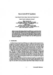
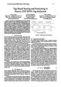
systems has customized requirements that currently are defined ad hoc. In addition, multiple, often competing, standards exist (ISO/IEC JTC1, ANSI, EPC, etc.) for RFID hardware, software, and data management. Thus, most of the RFID systems are being deployed for closed loop applications using either proprietary protocols or non-intersecting standards with non-reusable tags and readers. As a result, in most applications, RFID tag and reader hardware and software must be specifically designed for each particular application, and must be physically modified or re-designed every time the specification for the current application is adjusted, as new applications are introduced, and/or the standards are modified or new standards are developed. This keeps the overall design time long and the system costs high. Fig. 1 presents a comparison of different RFID tag design methodologies. The current state of the art tag development shown in Fig. 1(a) requires lengthy design, fabrication, and testing cycles which can take months with intellectual property (IP) reuse to years if developing new IP. A customizable RFID tag, as shown in Fig. 1(b), can handle variations in standards and requirements as they are developed with a significantly shorter time to market than current flows. Such a tag could be mass produced and tailored to a particular RFID use after fabrication. With the use of automation to program the device, the design time could be reduced to hours or days. This paper presents an extensible, low-power RFID tag system shown Fig. 2. The tag can be easily customized to work with different existing or newly developed standards and even concurrently with proprietary commands tailored to the desired application. The tag consists of a programmable controller, an air interface, and a power-aware smart buffer that sits in between. To program the controller, a
Extensible, lowpower RFID tag
Command
µprocessor core
Customized Controller FPGA IP block
Fig. 2. Extensible, low-power RFID tag.
design automation tool has been developed that allows RFID primitives or the commands employed by the RFID system to be specified using RFID macros, an assembly like format. These RFID macros are processed to generate a template file to specify the behavior for each primitive or macro. All behavior is specified using ANSI-C allowing the user to create arbitrarily complex behaviors. Finally, the RFID compiler generates the final controller used for managing the tag. This technique allows the seamless coexistence of several RFID standards such as the American National Standards Institute (ANSI) standard 256-2001 [1] and the International Standards Organization (ISO) standard 18000-7 [2]. In order to reduce the power consumption of the tag, the power-aware smart buffer manages the activation of the controller. Because RF signals broadcast to the entire system by nature, the tag will receive many RFID packets that are intended for other destinations such as point to point communications with other tags, and tags’ responses to
Design RFID Specification
Synthesis, Place & Route
Fabrication
Final Tag
Implement in VHDL
Correct Simulation?
Design Rule Checking
Testing
Current RFID tag design flow.All tag components integrated manually. Estimated time: months or years. b Smart Buffer
RFID Compiler
Smart Buffer
Response
a
Design RFID SpeciÞcation
Rx/Tx
Air Interface
Extensible, Low-power Tag
Automated RFID tag design flow.Prepackaged extensible silicon device. Estimated time: hours or days. Fig. 1. Comparison of RFID tag design philosophies.
118
A.K. Jones et al. / Microprocessors and Microsystems 31 (2007) 116–134
the reader. The smart buffer contains some logic to detect packets not intended for the local tag. Thus, the tag controller can be turned off until the smart buffer detects a packet that requires a response, saving system power. Because RFID packets are transmitted serially with kHz speed clocks, even allowing the controller to remain off while packets are buffered can contribute a significant power savings. To prove this design methodology, two RFID tag systems are presented. The first employs an embedded microprocessor core as the controller. This requires the RFID compiler to generate a C program that is compiled onto the microprocessor with its embedded C compiler. The second system replaces the microprocessor with an FPGA block requiring the RFID compiler to generate a controller in synthesizable VHDL. Both techniques integrate the smart buffer implemented directly in silicon with an existing transceiver. To prototype the system, the smart buffer was implemented in an FPGA. The remainder of the paper is organized as follows: Section 2 describes the related work in the RFID system and embedded system domains. Section 3 describes the RFID tag generation system, the stages of the RFID specification methodology and the compilation flow in detail for the microprocessor based system. Section 4 describes the algorithm and architecture for the RF Transceiver Coprocessor. Section 5 describes low-power FPGA implementation of the RFID primitive logic. Section 6 presents our results. Section 7 presents our conclusions and future research directions. 2. Related work Research and development in RFID has been focused on hardware and firmware components such as active and passive RFID tags, readers, and embedded software, for the purpose of its deployment in specific application domains. RFID is being incorporated in supply chain management, giving enterprises a real-time view on the location and integrity of their inventories [3]. RFID technology is used in a location sensing prototype system (LANDMARC) for locating objects inside buildings [4]. Novel architectures for deployments of RFID in libraries are described in [5]. RFID tags have been adopted in the Vatican Library in Rome to identify and manage its extensive book and document collection [6]. RFID tags and intelligent transponders are widespread for vehicle to roadside communications, road tolling, and vehicle access control [7]. The medical industry has also deployed RFID technology in ‘‘Mobile Healthcare Systems’’ for positioning and identifying persons and objects inside and outside the hospitals [8]. Different types of RFID prototype systems are being developed to support all aspects of aviation baggage tracking, sorting and reconciliation, which are surveyed in [9]. Recent research has focused on the collection and storage of RFID data using Geo-Time visualization [10]. Distributed Application Specification Language (DASL) has been
used to model and deploy software applications to process the RFID event data [11]. Most of the above RFID systems use proprietary hardware and software that cannot tolerate changes to the application or standard. However, the use of design automation for the development of flexible RFID systems has not been a topic of research. In the embedded systems domain, however, the need for meeting aggressive time-to-market requirements has lead to significant research to automate as many design steps as possible. Various design tools and specification methodologies such as Specification and Description Language (SDL), Architecture Description Language (ADL) and Unified Modeling Language (UML) are being used in embedded systems design. SDL [12] is increasingly being used as a formal, abstract description technique at the system level [13]. Optimizations for the performance of SDL derived system implementations and a tool that supports the complete development process are described in [14]. ADL is a language designed to specify architecture templates for SOCs. An ADL based co-design methodology that enables efficient design space exploration of SOC architectures and automatic software toolkit generation has been developed [15]. UML is an analogous approach that is a collection of notations for capturing a specification of a software system [16]. UML standards are used for specifying the requirements, documenting the structure, decomposing into objects, and defining relationships between objects in a software system. Some tools support code generation from the UML specifications, but are limited by the lack of formalized semantics. Embedded UML is a UML profile for embedded realtime system specification, design, and verification [17]. All of the above approaches have enabled the efficient development of embedded systems and mapping from specifications to the implementation models in significantly short times. Development of a complete RFID system from the specifications in general requires a large amount of design time and expertise, similar to the development of embedded systems. Like embedded systems, RFID systems will benefit from design approaches that can automatically generate target device software. Our contribution to the field of RFID systems design is a tool that can automatically generate the RFID tag controller software based on simple input specifications. This can significantly reduce the design time and the cost of deploying flexible RFID systems. 3. RFID specification methodology and compilation flow The typical format for RFID communications between the interrogator and transponder is a set of commands from the interrogator and a corresponding response or action on the transponder. The set of commands varies between the standards and must be augmented based on the needs of custom applications. Our RFID specification methodology and compilation flow automatically generates RFID tag controller code based on a description of the commands to be implemented.
119
A.K. Jones et al. / Microprocessors and Microsystems 31 (2007) 116–134
The RFID specification methodology and compilation flow are illustrated in Fig. 3. The RFID primitives from the specification of the standards and the proprietary extensions are first converted into RFID macros. The RFID Parser (rfpp), reads the macros and generates the tag behavior template. The user then defines the tag behavior in response to each RFID primitive in ANSI C. The RFID Compiler (rfcc) generates the tag controller C code
based on the input RFID macros and the tag behavior. The final C output of rfcc is compiled using an embedded compiler to generate executable code for the microprocessor of the tag. In Fig. 4, we provide an overview of the complete compilation flow for a specific set of example RFID primitives from the ISO standard. The process for converting the basic RFID structures from the standard specification
Convert to RFID Macros
RFID Parser rfpp
RFID Compiler rfcc
RFID Specification
Behavior Template
Include RFID Behavior
Embedded C Compiler
Fig. 3. RFID specification methodology and compilation flow.
Fig. 4. Example of compilation flow for ISO primitives.
µprocessor based RFID Tag
120
A.K. Jones et al. / Microprocessors and Microsystems 31 (2007) 116–134
[Fig. 4(a)] into a form read by the compiler [Fig. 4(b)] is described in Section 3.1. The process for inserting the RFID tag response behavior described in the standard [Fig. 4(d)] into the automatically generated behavior template [Fig. 4(c)] into the form read by the compiler [Fig. 4(e)] is shown in Section 3.2. Section 3.3 describes the process to generate the final program to run on the tag [Fig. 4(f)]. 3.1. Macros specification The simple assembly like descriptions corresponding to the RFID primitives and their responses are termed RFID macros. As an illustration of the RFID macro representation, a primitive ‘‘Owner id write’’ has been selected from the ISO/IEC 18000-7:2004(E) standard. The format of the fields in the primitive and its response are illustrated in Fig. 5. Each RFID primitive has a unique field called the command code or opcode which serves as the identifier. In addition to the opcode, each RFID primitive contains a number of other fields of varying lengths as positions
for data present as can be inferred from Fig. 5. Similarly, the tag response to each RFID primitive has a number of fields of varying lengths as positions of data present. Each RFID macro description has a short character string that corresponds to the name of the primitive, a number corresponding to the value of the opcode, a set of operands corresponding to the primitive’s format and a set of operands corresponding to the response format. Fig. 6 shows the RFID macros file corresponding to the Owner Id Write primitive. In order to capture the details of the lengths of each field in the primitive, the macros file has been conceptually broken into a declarations section and a main section. The declarations section allows the user to pre-declare the lengths of all the fields that will occur in the primitives and the responses. This eliminates the need to specify the field’s length multiple times because the field can occur in multiple primitives and/or multiples responses. In the main section, the primitives and the corresponding responses are defined in terms of these fields. In some cases, the fields in the primitive or the response have multiple nested fields of varying lengths. These fields can be described as shown in Fig. 6, thereby providing
Fig. 5. Owner id write primitive and response format (ISO).
Fig. 6. Macros specification.
A.K. Jones et al. / Microprocessors and Microsystems 31 (2007) 116–134
the user with the capability to adopt any level of granularity in manipulating the primitives and/or responses. In the macro below, the string used to denote the owner id write command is ionw. The decimal value of the command code corresponding to the owner id write command is ‘‘137’’. 3.2. Template for behavior The RFID interrogator (Reader) transmits an RFID primitive to the tag through an air interface. The tag responds to the interrogator’s primitive by way of changing its current state and/or transmitting a response message back to the interrogator. The user specifies tag behavior in a programming language such as ANSI C. To simplify the user interaction, the RFID parser generates a template for the response behavior indicating where the user must specify such custom behavior. Any C language constructs (conditionals, loops, etc.) can be added (or left unchanged) by the user to check the values of the fields of the incoming RFID primitive and to specify the values of the fields of the response. The template generated for the collection command (icol in the macros specification in Fig. 5) is shown in Fig. 7(a). A file containing similar templates for all the macros that were included in the macros specification file will be generated for the user. All details regarding the size and the position of the field in the interrogator command and in the response packet are built into the compiler. Hence the complexities of unpacking the command and packing the response are abstracted from the user as seen in Figs. 7(a) and(b). However, the user’s option to manipulate each individual field in the response has been preserved. Thus, the customization of responses and state changes can increase in complexity with user familiarity. The completed behavior for the icol command is shown in Fig. 7(b).
121
3.3. Compiler-generated RFID tag program The final phase of the compiler is the code generation based on the input macros specification and the tag behavior file. The compiler generates decode instructions that identify the incoming RFID primitive. For each case of an incoming command, the compiler also creates routines that unpack the command into the appropriate fields. The corresponding behavior is then attached for each possible incoming command. The routines for packing the response are then generated. The result is that the final generated RFID C program, from the above steps, receives the incoming RFID primitive, identifies it based on the value of its opcode, unpacks its fields, executes its behavior, packs its response and sends it to the interrogator. 3.4. Extensibility To demonstrate that our compiler is extensible, we illustrate its use in a potential RFID application scenario where the RFID tag has the capability to respond to primitives from multiple standards (ISO and ANSI), and to proprietary primitives. It is possible that suppliers need to supply their RFID-tagged shipments to retailers in different countries who may mandate different RFID standards e.g. shipping between Europe where ISO is likely to be in use and the USA where ANSI is used. In such a scenario, it would be greatly beneficial for the supplier to use tags that are capable of responding to both standards. In addition, in the example of warehouse management, the supplier would also want the tags to have proprietary primitives such as setting and querying positions, manufacture dates, prices, and product codes of the products. The original macros file can be extended to add the new example primitives from ANSI as well as the example custom primitives. Fig. 8 shows the new macros specification file after
Fig. 7. Tag behavior for collection command.
122
A.K. Jones et al. / Microprocessors and Microsystems 31 (2007) 116–134
Fig. 8. Extended macros specification.
a set of new primitives has been added to the original macros specification file from Fig. 5. The new macros that are being added correspond to the ANSI primitives, ‘‘Get Error’’ (ager), ‘‘Set Beeper On’’ (abpn), and the custom primitives ‘‘Set Position’’ (spos), ‘‘Get Position’’ (gpos), ‘‘Get Manufacture Date’’ (gdat), and ‘‘Get Product Code’’ (gcod). The new field declarations are appended to the declarations section and the new macros declarations are appended to the main section in the original macros file. The compiler then generates the template for the behavior of the tag in response to the current set of primitives. The user edits the templates to plug in the behavior, and the compiler generates the RFID C program to be executed on the tag. 4. The smart buffer To reduce the power consumption of the embedded processor based tag, it is necessary to decrease the time when the processor is active. Therefore, an RF transceiver coprocessor was created to manage buffering messages to and from the transceiver and activating the processor for responding to RFID primitives when necessary. Thus, the RF transceiver coprocessor or smart buffer assists the embedded processor to sleep or stay in a low-
power idle mode while any non-relevant packets arriving at the RFID tag are ignored when valid packets arrive, the smart buffer must also wake up the processor to respond appropriately. The amount of power savings allowed by the smart buffer is highly dependent on the scenerio. First, the smart buffer must consume less power than the active tag controller, which is supported by the data shown in Section 6. Secondly, the amount of power savings depends on how many successful accesses the tag receives on average. However, even if each transaction requires a full second of active time and there are 100 transactions per day (both conservative estimates) this results in nearly 99.9% inactive time for the tag. Thus, any significant savings between the smart buffer power and the active power will be realized in almost its entirely using the smart buffer. As seen in Section 6 this difference can be several orders of magnitude for the microprocessor based tag. 4.1. Algorithm for RF transceiver coprocessor The conceptual flow in Fig. 9 shows the mechanism for the RF transceiver coprocessor i.e. the smart buffer. In the first four states highlighted as green, the smart buffer
A.K. Jones et al. / Microprocessors and Microsystems 31 (2007) 116–134
Listen
123
Wakeup processor Send Interrupt
Receive preamble
Error – not match timing contraint
Check
Noise/ Not Valid Preamble
Valid Preamble Receive Manchester code
Check
Not intended for me
Proc read Transfer Data to processor
Proc write Generate Preamble
preamble
Analyze Packet
Check Tag ID Check Group ID
Check
Generate Manchester Code
Manchester Done Smart Buffer back to Listen
Fig. 9. The conceptual flow of the smart buffer.
verifies the message preamble and buffers the incoming packet. The smart buffer then checks to see if the packet was intended for this particular tag. The processor is not used to make the check, it is done in hardware while the processor remains idle or asleep. As a result, only the smart buffer consumes power. If the incoming packet is invalid, the smart buffer will ignore it and go back to the listen state. If the incoming packet is identified as an intended packet for the Tag, by matching the tag ID or group ID from the packet, the smart buffer will wake up the processor to process the packet. The processor reads data from the smart buffer and responds correspondingly. After the processor writes response data back to the smart buffer, the smart buffer generates a bit stream of data consisting of a preamble signal and the response data with Manchester coding. It is at this point that the processor returns to the low-power mode. Upon completion of sending the packet response, the smart buffer returns to listening for the next preamble.
Fig. 10 depicts the top level diagram of the smart buffer. The smart buffer has four I/O pins to the RF front end circuit. The blocks described in Fig. 10 are enumerated as follows: Preamble removal unit: Detects the incoming preamble signal and differentiates between signals intended for tags and readers. Item Manchester decoder: Converts Manchester code into binary values. Preamble generator: Generates the Manchester code for the tag response. Packet analysis unit: Detects ID flags to determine whether to wake up the processor. Interrupt process unit: Generates an interrupt to the processor. Processor control command unit: Communicates data to and from the processor. Air interface unit: Communicates data to and from the air interface.
124
A.K. Jones et al. / Microprocessors and Microsystems 31 (2007) 116–134
Fig. 10. The top-level block diagram for the smart buffer architecture.
4.2. Preamble removal unit
4.3. Manchester decoder
The preamble removal unit detects a valid incoming preamble signal. It receives bit stream data from the RF front end circuit. This digital bit stream data is converted from an analog signal the RF circuitry receives from the antenna. However, because the input signal is analog, a signal may be due to noise rather than a preamble. Therefore, the smart buffer has the ability to tolerate noise and only recognize the valid preamble signal. The specification of the preamble signal is defined in the ANSI and ISO standards [1,2]. The preamble signal begins with a series of pulses with 30 ls high followed by 30 ls low. Every preamble signal, regardless of whether it has originated from a tag or a reader has 20 of these regular pulses. These 20 regular pulses are followed by the final sync pulse, which determines whether a tag or reader originated the preamble. If an RFID packet comes from a tag, the final sync pulse is 42 ls high and 54 ls low. If an RFID packet comes from a reader, the final sync pulse is 54 ls high and 54 ls low. The smart buffer can ignore RFID packets which come from other tags by checking the length of the final sync pulse. It will only focus on RFID packets from interrogators as long as the sync pulse is 54/54 pattern. Other packets are not buffered. The implementation of the preamble removal unit uses four times oversampling within each 30 ls period for each pulse. The design utilizes counters to count the sampling period. The difference in the sync pulse can be detected by counting for how many samples the final signal is high, 5 for tags and 7 for readers.
The Manchester decoder translates the Manchester encoded data immediately following a valid preamble. It is the block for filtering and buffering incoming RFID packets. The decoder extracts a bit stream of Non-Return to Zero (NRZ) data from the encoded data. The Manchester code combines the concept of clock with synchronous data into a single serial data stream as shown Fig. 11. In order to enforce synchronization, Manchester code contains a transition in the middle of each Manchester bit. The Manchester bit represents zero (0) NRZ data if this transition is from high to low. Similarly, the Manchester bit represents one (1) NRZ data if the transition is from low to high. By representing data with a guaranteed transition for each bit, slight discrepancies of timing can be tolerated without disrupting the communicated data. The timing specification of the Manchester code is defined in the ISO and ANSI standards. The Manchester decoder block converts eight serial decoded data bits into a parallel 8-bit datum (e.g. byte). In addition, the Manchester code contains a ninth bit for synchronization which is always ‘0’. This is called a stopbit, and is removed during decoding. Each byte is stored in an output FIFO shown in Fig. 10. When the decoder detects the final bit of an RFID packet, it stops storing data into the FIFO and asserts the end of packet (EOP) signal to the interrupt process unit. Based on the analysis result, the interrupt process unit determines if it is necessary to wake up the processor.
125
A.K. Jones et al. / Microprocessors and Microsystems 31 (2007) 116–134 Table 1 Packet analysis algorithm for the ISO standard Input
Output
B/P2P
Owner ID field?
Owner ID in tag?
Process command?
B B B B P2P P2P P2P P2P
No No Yes Yes No No Yes Yes
No Yes No Yes No Yes No Yes
Yes No Yes If Owner ID match If Tag ID match If Tag ID match If Tag ID match If Tag ID and Owner ID match
Table 2 Packet analysis algorithm for the ANSI standard
Fig. 11. Example of Manchester encoding.
4.4. Packet analysis unit Based on the header information obtained from the RFID packet, the packet analysis unit attempts to determine specific characteristics of this particular packet needed to decide whether to wake of the processor for response generation. These elements include (1) the primitive operation code (or opcode), (2) the tag id for which the packet is intended, and/or (3) some other distinguishing information or id from the packet. Both the ISO or ANSI standards have their own algorithms for tags to identify RFID packets. Therefore, the packet analysis unit has the ability to switch between those two algorithms seamlessly. For example, if the tag travels to Europe or Asia where the RFID system follows the ISO standard, the smart buffer can perceive that it being accessed by ISO primitives. However, if the tag returns to the United States, it switches over to recognizing ANSI commands. For broadcast commands, both standards allow partitioning of the tags into different bins with a unique identifier where a logical bin can contain an unlimited number of tags. This is accomplished by assigning that unique id to each tag contained within the bin. In ISO this is called the Owner ID and for ANSI the Group ID. For point to point commands, a Tag ID is used distinguish the destination tag. The packet analysis algorithms are summarized in Tables 1 and 2. In both standards, commands are segregated into broadcast commands and point to point (P2P) commands. If the tag receives an ISO broadcast command, it always responds if no Owner ID is set within the tag. If an Owner ID is set, the tag only responds if an Owner ID is included in the command and it matches the stored Owner ID. For ANSI, broadcast commands are subdivided between 3 opcodes, 30, 16, and 35. If the opcode is either 16 or 35, the tag always responds. If the opcode is 30, the tag only responds if the internal Group ID matches
Input Opcode
Output Process command?
30 16 35 P2P
If Group ID matcha Yes Yes If Tag ID match
a A group ID match always occurs if the currently stored group ID within the tag is zero (0).
the primitive Group ID. ANSI specifies that a stored Group ID of zero (0) always results in a match. For point to point commands, both standards require a Tag ID match. However, ISO requires the Owner ID must match as well as the Tag ID for point to point commands with an Owner ID present in both the tag and command. Once the packet analysis unit verifies that the packet requires a response, it sends a signal to the interrupt process unit to process the packet stored in the FIFO. Because the packet analysis occurs in parallel with the packet buffering, a signal can be sent to the interrupt unit prior to the entire packet being buffered. If the packet does not require processing it is dropped from the FIFO. This prevents the processor from being powered up unless it is needed to process the packet. 4.5. Interrupt process unit The interrupt process unit will wake up the processor only when a whole RFID packet is stored into the output FIFO and the analysis result forwarded by the packet analysis unit is positive. Fig. 12 shows the state diagram for the interrupt procedure. The interrupt process unit will go back to the idle state after sending an interrupt signal to the processor. 4.6. Command control unit The command control unit fetches control commands from the processor, such as read and write data to FIFO, update Tag ID or Group/Owner ID, starts the transmission procedure, and so forth. For processor compatibility,
126
A.K. Jones et al. / Microprocessors and Microsystems 31 (2007) 116–134
the direction of I/O is from processor to smart buffer and dir = 1 is the reverse. Because the smart buffer and processor are operated in two different clock domains, a hand-shaking communication approach is required to push/pull data to/from the FIFOs. Therefore, it is necessary to dedicate more than one cycle to transmit a single byte of data between the processor and FIFO. Once the processor has generated a response and completed pushing the response data into the FIFO, it sends the transmit command. This signals the smart buffer to generate the preamble signal, convert data in the FIFO to a serial data stream and encode the bit stream data in Manchester coding. 4.7. Preamble generator
Fig. 12. The interrupt finite state machine.
it was desirable to minimize the number of lines between the processor and the smart buffer. Thus, four (4) parallel lines are utilized to communicate the processor to buffer command control. The processor to smart buffer commands are illustrated in Fig. 12. After waking up the processor, the smart buffer listens for the processor to initiate commands for data communication. As shown in Fig. 12, the control unit decodes 4-bit processor commands into 5 basic operations: transmit, update, push, pull, and null. The double circle represents a potentially multi-cycle operation. Based on different control commands, the unit will determine the direction of the bi-directional smart buffer, processor interface. In Fig. 13, dir = 0 represents that
According to the ISO and ANSI standards, the preamble generator generates a preamble signal with 20 pulses of 60 ls, 30 ls high and 30 ls low, followed by the final sync pulse. Because of this RFID packet generated from a tag, the final sync pulse is 42 ls high and 54 ls low. The preamble generator utilizes several counters to trace the period time for each pulse. Those counters are running with the smart buffer system clock at 33 MHz. Therefore, the preamble signal will be skewed less than 1 ls requiring the reader to tolerate an error of ±3.3%. In order to help the receiver filter out an ambient noise in the air, a mark state, or a stable logic low signal for 120 ls is generated and transmitted just prior to the preamble signal. While the preamble generator creates the mark state and preamble signal, the air interface unit forces the rx_enable signal low and raises the tx_enable signal. When the final sync pulse is transmitted, the preamble generator informs the Manchester encoder to begin to out-
Fig. 13. Fetch and operation diagram for the command control unit.
127
A.K. Jones et al. / Microprocessors and Microsystems 31 (2007) 116–134
set low at all times except when the smart buffer is ready to transmit an RFID response packet back to readers. Input FIFO
5. Hardware synthesis of primitives
next 8-bit data
Current 8-bit data
shift registers
stop bit
Encode
Manchester encoded data
Coding clock generator
Fig. 14. Top-level diagram for the Manchester encoder.
put its serial encoded data immediately. Any significant gap between data and the preamble signal may cause an error, which may not be tolerated in the system. 4.8. Manchester encoder The Manchester encoder starts encoding the data in the input FIFO after it is notified by the preamble generator. This notification occurs during the transmission of the final sync pulse to give the encoder enough time to have the first byte of data ready. First, the Manchester encoder converts the next available byte in the FIFO to eight (8) single serial bits. Those eight (8) bits are individually stored in single-bit shift registers. In addition, a stop bit needs to be appended for each byte of data in the shift registers. The Manchester encoded data is the output of a NRZ data XOR coding clock, shown in Fig. 11. The NRZ data is synchronized with the coding clock. According to the specification of ISO and ANSI standard, the period of coding clock is 36 ls; 18 ls high and 18 ls low. This clock signal is generated in the Manchester encoder block. The Manchester encoder combines the coding clock and serial data as shown in Fig. 14. 4.9. Air interface unit The air interface unit has two output control signals, tx_enable and rx_enable. Since the smart buffer defaults to listening for incoming signals from the air, the rx_enable signal is set high and tx_enable signal is
The overhead of using a microprocessor based controller for the RFID tag is considerable. For example, Intel StrongARM and XScale processors operate in the hundreds of mW range. While the smart buffer is intended to alleviate much of the controller’s power consumption by putting the processor to sleep, the ARM based processors can require hundreds of instructions to be executed to generate the response for a single primitive. This can result in significant energy usage even with the smart buffer. A hardware based solution is more desirable for energy consumption. However, if the RFID tag is to remain programmable, direct silicon implementation may not be possible. High-performance FPGAs tend to have undesirable power characteristics and are generally not considered for low-power applications. However, the logic required by the RFID tag primitive response generation can fit into a Xilinx Coolrunner II, which offers low-power results. This section examines extensions to the microprocessor based design flow to allow an RFID tag to be developed for which the air interface and smart buffer components are fixed and implemented in silicon and the RFID primitive logic is synthesized automatically for a Xilinx Coolrunner II. 5.1. Compiler extensions for synthesis In order to synthesize primitives into VHDL a new Hardware RFID compiler was developed based on both the automated C program generation described in Section 3.3 and the SuperCISC compilation flow described in [18,19]. The RFID compiler generates a complete application in C that is compiled for the target microprocessor in the RFID Tag. While the behavior is specified in C by the user, much of the remaining C code is automatically generated from the RFID macros. For the hardware RFID compiler, this automatically generated code segment was output in VHDL rather than C. In many ways, generating the VHDL code from the RFID macros is more natural as VHDL handles arbitrary bit widths more easily than C/C++.
Convert to RFID Macros
RFID Parser rfpp
RFID Compiler rfvhd
Xilinx ISE
RFID Specification
Behavior Template
Include RFID Behavior
SuperCISC Compiler
Fig. 15. Compilation flow for an FPGA-based tag.
FPGA based RFID Tag
128
A.K. Jones et al. / Microprocessors and Microsystems 31 (2007) 116–134
a
b
Fig. 16. Synthesis process for the ‘‘Owner id write’’ (ionw) command.
129
A.K. Jones et al. / Microprocessors and Microsystems 31 (2007) 116–134
Because C is a more universally known language than VHDL or Verilog, it is desirable to continue having the end-user specify the primitive behaviors for the RFID Tag in C code. This requires that the C code be converted in synthesizable hardware code. Preferably, this code would also be as simple as possible and optimized for power. The compilation flow the for the FPGA-based RFID tag is displayed in Fig. 15. This flow is very similar to the flow from Fig. 3, automatically generating a behavioral template from the RFID macros. The completed behavior in ANSI-C is fed into the SuperCISC compiler [18,19] and combined with automatically generated VHDL in the RFID Compiler rfvhd. The resulting synthesizable VHDL is synthesized, mapped, placed, and routed for the target FPGA device using commercially available tools. The prototype system was targeted for a Xilinx Coolrunner II, however, any low-power reprogrammable device or IP block could be used. Fig. 5 shows the conversion of the input C code into combinational hardware. First, the C code is represented in a control and data flow graph (CDFG) representation as shown in Fig. 16(a) for the ‘‘Owner id write’’ (iown) primitive. CDFGs are commonly used within compilers for transformations and optimizations. Many behavioral synthesis tools also use CDFGs as their internal representation [20,21]. The CDFG shown in Fig. 16(a) has the control flow graph (CFG) on the far left. The edges between each block represent control dependencies. Generally, control dependencies indicate that a decision must be made. Often, cycle boundaries are created due to control dependencies during synthesis of CDFGs. Each block in the CFG is a basic block containing a data flow graph (DFG). All of the basic blocks in the CFG are shown to the right of the CFG. Edges in the DFG represent data flow dependencies creating combinational
flow (e.g. no cycle boundaries) during behavioral synthesis (Fig. 16). The SuperCISC compiler translates the CDFG into an entirely combinational representation called a super data flow graph (SDFG). This process takes advantage of several well known compiler transformations such as loop unrolling and function lining as well as a technique called hardware predication to convert all control dependencies into data dependencies creating an entirely combinational representation. The SDFG for the ionw is shown in Fig. 16(b). Because the SuperCISC technique removes the need for many potentially high-power consumption sequential constructs such as registers and clock trees, SDFG based hardware implementations are extremely power efficient [22]. 6. Results The prototype microprocessor system was simulated using an Altera APEX 20 FPGA for smart buffer implementation and three different processor cores: the Intel StrongARM at 206 MHz [23], the Intel XScale 80200 at 733 MHz [24], and the 16-bit EISC microprocessor at 50 MHz from ADChips [25]. A prototype system was built with an Avnet development board, an EISC development board, and an air interface prototype board fabricated using PCB Express. The system was tested with a variety of automatically generated controller programs including anywhere from 1 to 14 Primitives. While fitting additional primitives in the prototype system is theoretically possible, limitations of available memory on the board prevented a larger program size from being used. The prototype FPGA-based system was implemented in simulation using a Xilinx Spartan 3 XC3S400 FPGA to implement the smart buffer and a Xilinx Coolrunner IIXC2C512 to implement the primitive logic programmed into the microprocessor in the previous system. The entire
Table 3 Area and performance result for implementing the smart buffer and primitive logic on a Spartan 3 XC3S400 Primitives
2
4
6
8
10
12
15
20
24
30
35
40
LUTs % used FMax (MHz)
1946 27% 70
1948 27% 70
1958 27% 70
1971 27% 70
2003 27% 68
2061 28% 70
2420 33% 68
2576 35% 67
2594 36% 66
2612 36% 65
2692 37% 65
2704 37% 67
Table 4 Area and performance result for implementing the primitive logic on a Coolrunner II XC2C512 Primitives
2
4
6
8
10
12
15
20
24
30
35
40
Macrocells % used
332 66%
335 66%
338 67%
340 67%
350 69%
366 72%
426 84%
447 88%
447 88%
447 88%
449 88%
447 88%
Product terms % used
444 25%
477 27%
514 29%
506 29%
477 27%
552 31%
772 44%
953 54%
993 56%
1106 62%
1181 66%
1213 68%
Registers % used
262 52%
267 53%
271 53%
271 53%
283 56%
307 60%
422 83%
443 87%
443 87%
443 87%
443 87%
443 87%
Func. Block Inputs % used
360 29%
379 30%
408 32%
391 31%
338 27%
396 31%
611 48%
767 60%
801 63%
870 68%
900 71%
914 72%
FMax (MHz)
49
41
41
40
49
41
41
29
33
33
26
30
130
A.K. Jones et al. / Microprocessors and Microsystems 31 (2007) 116–134
Fig. 17. Resource utilization for FPGA-based prototype systems.
system was also loaded onto a single Spartan 3 XC3S400 and tested in hardware. The system was tested with 2 primitives up to 40 primitives. Forty primitives was selected as the maximum because it provided room for all primitives of the ANSI and ISO standard, with room for several customized primitives. The area and performance results are shown in Table 3 for the XC3S400 and Table 4 for the XC2C512 and are summarized against available resources in Fig. 17. For both the microprocessor and FPGA-based tags, the final implementation would use an ASIC based smart buffer due to its unchanging design and its purpose for power savings. Thus, the FPGA-based smart buffers in both prototypes were used for functional verification only. 6.1. Power estimation Power optimization is critical in RFID systems because the power supplied to the tags is limited in the
passive case and battery drain needs to be limited in the active case. Because active systems are designed for extremely low-cost large-scale applications, frequent replacement of batteries is not feasible. So far, some research has been done to minimize power consumption of anti collision protocols [26] and to implement energy conserving access protocols [27] in RFID systems. While the smart buffer provides a power down capability to the controller, it is still important to reduce power/energy consumption while the controller is active to increase battery lifetime. 6.1.1. Microprocessor-based tag The RFID compiler was used to generate two different programs: Program A with 24 RFID primitives, Program B with 12 primitives, and Program C with 4 RFID primitives. Experiments were conducted by executing 14 primitives of Program A, 1 primitive of Pro-
131
A.K. Jones et al. / Microprocessors and Microsystems 31 (2007) 116–134 Table 5 Power consumption results for microprocessor based RFID tag during response generation Description Program Program Program Program
A (14 primitives) A (1 primitive) B (1 primitive) C (1 primitive)
Average power (mW)
Energy (lJ) a
StrongARM
XScale
EISC
StrongARM
XScale
EISCb
411 314 322 314
307 244 257 249
30 30 30 30
672 140 183 140
170 32 43 32
– – 19 17
– means program did not fit within instruction memory. a Static power estimation provided by ADChips [25]. b Energy calculation is static power consumption multiplied by measured execution time.
gram A, 1 primitive of Program B, and 1 primitive of Program C. The sim-panalyzer [28] and XTREM [29] tools were used to estimate the power dissipation of our compiler-generated microprocessor based tag for the ARM based cores. Sim-panalyzer is a cycle accurate, architecture level power simulator built on the SimpleScalar processor simulator. XTREM is a SimpleScalar-based power and performance simulator tailored specifically for the Intel XScale microarchitecture. We used SimpleScalar’s sim-profile tool to obtain ARM instruction and instruction class profiles for our software. Because an instruction set simulator was not available for the EISC processor, the application was run on the development board and the execution time was measured by setting a pin output from low to high upon each iteration. The total duration was measured using an oscilloscope. The energy consumed by the EISC was based on a static power estimate from ADChips [25], which should be within about 10% accuracy of an instruction level power estimation approach [30]. Table 5 shows the power consumption results of our program on the Intel StrongArm SA-110 [23] and Intel XScale 80200 [24], and the ADChips 16-bit EISC [25]. These results show the power consumption only during the active phase of the RFID transaction (e.g. the time after the entire packet is received by the smart buffer when the packet is processed and the response is generated by the smart buffer). During this time, the smart buffer is active, however as seen for the ASIC implementation in Table 7 this power is negligible compared to the processor power. Both ARM based processors operate in the 250–400 mW range, while the XScale uses significantly less energy (10 s versus 100 s of lJ). The EISC processor uses an order of magnitude less power than the ARM based cores, but operates much slower. However, the energy consumed is still less than half of XScale. It can be seen that the power consumption of XScale is less than that of StrongArm though they both implement the ARM Instruction Set Architecture. This is because the XScale family of microprocessors uses deep pipelines and micro-architectural optimizations for high performance [24]. Further, the reduced power consumption and greater clock speed of XScale 80200 result in its far lower energy consumption.
6.1.2. FPGA-based tag While the embedded processor approach does provide a reasonable power/energy consumption, improvement is still possible. Ideally, the EISC processor would be used for low-power purposes, however, system memory is a limitation. To improve both the power and capacity of the controller, an FPGA solution is considered. The power consumption of the FPGA devices including the Spartan 3 and Coolrunner II were estimated using Xpower from Xilinx. Switching statistics for the tool were generated from cycle-accurate, post place and route simulations of actual test data. While the Spartan 3 certainly provides plenty of capacity, its power consumption, albeit potentially lower than the ARM based processors, is still not as low as desired. Unfortunately, much of this is due to the quiescent power of 92 mW. In order to further reduce power, the Coolrunner II was explored. For this system, the smart buffer is not implemented in the reconfigurable logic of the Coolrunner. Only the user defined primitive controller generated by the compiler is implemented in the Coolrunner. The power and energy consumption of the Coolrunner-based RFID tag controller are displayed in Table 6. 6.1.3. Smart buffer implementation The smart buffer was prototyped on the Spartan 3 FPGA as well as studied for ASIC implementation using Table 6 Power and energy results for implementing the primitive logic on a Coolrunner IIXC2C512 Number of primitives 2 4 6 8 10 12 15 20 24 30 35 40
Power (mW)
Energy (lJ)
Dynamic
Quiescent
Total
Total
1.06 1.06 1.06 1.07 1.06 1.06 1.24 1.24 1.24 1.24 1.24 1.24
0.05 0.05 0.05 0.05 0.05 0.05 0.05 0.05 0.05 0.05 0.05 0.05
1.11 1.11 1.11 1.12 1.11 1.11 1.29 1.29 1.29 1.29 1.29 1.29
0.00111 0.00111 0.00111 0.00112 0.00111 0.00111 0.00129 0.00129 0.00129 0.00129 0.00129 0.00129
132
A.K. Jones et al. / Microprocessors and Microsystems 31 (2007) 116–134
Table 7 ASIC versus FPGA power consumption for portions of the smart buffer Component
Spartan 3
0.16 lm ASIC
Wake-up signal Preamble detection Manchester decoder Quiescent power
0.01 mW 0.87 mW 0.95 mW 92 mW
0.001 mW 0.005 mW 0.284 mW 0 mW
Total
93.83 mW
0.29 mW
0.16 lm OKI standard cells. While it was possible to implement FIFO blocks on the Spartan 3 FPGAs using Xilinx IP blocks, ASIC versions of these FIFOs were not available. In order to study the impact of having the smart buffer in an ASIC versus the Spartan 3 FPGA, three components were separated from the larger design and synthesized and power profiled independently. These blocks include the preamble detection, a 30 kHz wake-up signal detection, and the Manchester decoder. The results for power estimation of the ASIC and Spartan 3 based smart buffer components are displayed in Table 7. Both power analyses are based on post synthesis simulation with the exact same stimuli. The FPGA power results were computed using Xilinx Xpower and the ASIC power results were calculated using Synopsys PrimePower. Based on the results from Table 7 the ASIC version of the implementation uses orders of magnitude less dynamic power for all three components. Interestingly, the quiescent power alone is nearly three orders magnitude greater than the dynamic power of the ASIC. 7. Conclusions and future research This paper presents an extensible, low-power RFID tag with associated design automation flow. The RFID compiler automatically generates RFID tag software or hardware for both microprocessor and FPGA-based extensible tags. The compiler takes as input simple descriptions called RFID macros of the RFID primitives described in the standard and behavior for each primitive written in C. The system is extensible, in that it allows for addition (or removal) of a set of custom RFID primitives that may be a subset or superset of the original standard(s). Additionally, with the use of smart buffering, it is possible to allow the tag to save power by ignoring RFID packets destined for readers or other tags while retaining the ability to respond to valid broadcast or P2P messages. To select the appropriate tag architecture for an extensible low-power tag, consider the power consumption for several different tag systems described in Section 6.1. Based on the results from Section 6.1.3 coupled with the fact that the smart buffer does not require reconfiguration except in drastic redesign of RFID systems, implementing the smart buffer directly in silicon is the preferred option. To allow the tag controller to be configurable, a direct silicon implementation is not acceptable. Thus, the two prototypes are either microprocessor based or FPGA based for reconfigurability. Three low-power embedded
microprocessors were selected and power profiled in Section 6.1.1. In terms of energy consumption, Stron-gARM is consistently 4–6 times worse than XScale requiring hundreds of lJ compared to tens of lJ for XScale. For ease of comparison, consider program B which contained 12 primitives. This program was run or modeled successfully on all platforms. Of the microprocessors, StrongARM performed the worst, requiring about 4 times more energy than an XScale and almost 10 times that of an EISC. However, for the same primitives running on a Coolrunner II FPGA, the required power drops from tens or hundreds of mW to 1.1 mW. Additionally, the response generation computation is done much faster, requiring a single 1 MHz clock cycle to complete. Thus, the energy required by the Coolrunner is in the nJ range while the best performing processor (EISC) still requires 17 lJ. Additionally, the Coolrunner quiescent power is approximately 50 lW,a reasonable power consumption for idle modes of an active RFID tag. References [1] American National Standards Institute, Ansi ncits 236:2001, Standard Specification, 2002. [2] International Standards Organization, Iso/iec fdis 18000-7:2004(e), Standard Specification, 2004. [3] S.E. Sarma, S.A. Weis, D.W. Engels, Rfid systems, security and privacy implications, 2002, . [4] L.M. Ni, Y. Liu, Y.C. Lau, A.P. Patil, LANDMARC: indoor location sensing using active RFID, Wireless Networks 10, 2004. [5] D. Molnar, D. Wagner, Privacy: privacy and security in library RFID: issues, practices, and architectures, in: Proceedings of the 11th ACM Conference on Computer and Communications Security, 2004. [6] TI, Texas instruments’ RFID technology streamlines management of vatican library’s treasured collections, 2004, . [7] P. Blythe, RFID for road tolling, road-use pricing and vehicle access control, in: Proceedings of IEE Colloquium on RFID Technology (1999/123). [8] C. Li, L. Liu, S. Chen, C.C. Wu, C. Huang, X. Chen, Mobile healthcare service system using RFID, in: Proceedings of IEEE International Conference on Networking, Sensing and Control, vol. 2, 2004. [9] A. Cerino, W.P. Walsh, Research and application of radio frequency identification (RFID) technology to enhance aviation security, in: Proceedings of the IEEE National Aerospace and Electronics Conference, 2000. [10] D. Shuping, W. Wright, Geotime visualization of RFID supply chain data, March 2005, . [11] M. Kaundinya, A. Syed, Modeling event driven applications with a specification language (MEDASL), in: Companion to the 19th annual ACM SIGPLAN Conference on Object-Oriented Programming Systems, Languages, and Applications, 2004. [12] ITU-T, ITU-T recommendation Z.100: CCITT specification and description language (SDL), 1994. [13] A. Muth, T. Kolloch, T. Maier-Komor, G. Farber, An evaluation of code generation strategies targeting hardware for the rapid prototyping of SDL specification, in: Proceedings of the 11th International Workshop on Rapid System Prototyping, 2000, pp. 134–139. [14] C.L. Pereira, D.C.D. Silva, R.G. Duarte, A.O. Fernandes, L.H. Canaan, C.J.N. Coelho, L.L. Ambrosio, JADE: an embedded systems specification, code generation and optimization tool, in: Proceedings of the 13th Symposium on Integrated Circuits and Systems Design, 2000, pp. 263–268.
A.K. Jones et al. / Microprocessors and Microsystems 31 (2007) 116–134 [15] A. Halambi, P. Grun, H. Tomiyama, N. Dutt, A. Nicolau, Automatic software toolkit generation for embedded systems-on-chip, in: Proceedings of the 6th International Conference on VLSI and CAD, 1999, pp. 107–116. [16] J. Rumbaugh, I. Jacobson, G. Booch, The Unified Modeling Language Reference Manual, 1998. [17] G. Martin, L. Lavagno, J. Louis-Guerin, Embedded UML: a merger of real-time UML and co-design, in: Proceedings of the Ninth International Symposium on Hardware/Software Codesign, 2001, pp. 23–28. [18] A.K. Jones, R. Hoare, D. Kusic, J. Fazekas, J. Foster, An fpga-based vliw processor with custom hardware execution, in: Proceedings of the ACM International Symposium on Field-Programmable Gate Arrays (FPGA), 2005. [19] R. Hoare, A.K. Jones, D. Kusic, J. Fazekas, J. Foster, S. Tung, M. McCloud, Rapid vliw processor customization for signal processing applications using combinational hardware functions, EURASIP Journal on Applied Signal Processing, 2006. [20] X. Tang, T. Jiang, A. Jones, P. Banerjee, Compiler optimizations in the pact hdl behavioral synthesis tool for asics and fpgas, in: Proceedings of the IEEE International SoC Conference (IEEE-SOC), 2003. [21] S. Gupta, N.D. Dutt, R.K. Gupta, A. Nicolau, Spark: a high-level synthesis framework for applying parallelizing compiler transformations, in: Proceedings of the International Conference on VLSI Design, 2003. [22] A.K. Jones, R. Hoare, D. Kusic, G. Mehta, J. Fazekas, J. Foster, Reducing power while increasing performance with supercisc, ACM Transactions on Embedded Computing Systems (accepted for publication). [23] Intel, SA-110 microprocessor technical reference manual, 1998, . [24] Intel, Intel PXA27x processor family developers manual, 2004, . [25] Y. Cha, Eisc core, Presentation to University of Pittsburgh, February 2005. [26] F. Zhou, C. Chen, D. Jin, C. Huang, H. Min, Wireless application drivers for low-power systems: evaluating and optimizing power consumption of anti-collision protocols for applications in RFID systems, in: Proceedings of the 2004 International Symposium on Low power Electronics and Design, 2004. [27] I. Chlamtac, C. Petrioli, J. Redi, Energy-conserving access protocols for identification networks, IEEE/ACM Transactions on Networking (TON) 7 (1), 1998. [28] Sim-panalyzer, Simplescalar-ARM power modeling project, . [29] C. Gilberto, M. Martonosi, J. Peng, R. Ju, G. Lueh, XTREM: a power simulator for the intel xscale core, in: Proceedings of the 2004 ACM SIGPLAN/SIGBED Conference on Languages, Compilers and Tools, vol. 39, 2004, pp. 115–125. [30] J. Russell, M. Jacome, Software power estimation and optimization for high performance, 32-bit embedded processors, in: Proceedings of the International Conference on Computer Design (ICCD), 1998, .
Alex K. Jones is currently an Assistant Professor of Electrical and Computer Engineering and Assistant Professor of Computer Science at the University of Pittsburgh. He received his B.S. from the College of William and Mary in 1998. He received his M.S. and Ph.D. degrees from Northwestern University in 2000 and 2002, respectively.
133
Raymond Hoare is an Assistant Professor of Electrical and Computer Engineering at the University of Pittsburgh. He earned his B.E. degree from Stevens Institute of Technology in 1991, his M.S. from the University of Maryland in 1994 and his Ph.D. in from Purdue University, in 1999.
Swapna Dontharaju is a Ph.D. candidate in Electrical and Computer Engineering at the University of Pittsburgh. She received her B.E. in Electrical and Electronics Engineering from the Regional Engineering College (NIT), Trichy, in 2002. She received her M.S. in Computer Science and Engineering from the Pennsylvania State University, in 2004.
Shenchih Tung is a Ph.D candidate in Electrical and Computer Engineering at the University of Pittsburgh. He received his B.S. degree in Electrical Engineering from the National Taiwan Ocean University in 1997. He received his M.S. in Telecommunications at University of Pittsburgh in 2000.
Ralph Sprang is a Ph.D. student in Electrical and Computer Engineering at the University of Pittsburgh. He holds a B.S. in Electrical Engineering from the Ohio State University and an M.S. in Electrical Engineering from the Johns Hopkins University. His research interests include hardware acceleration of computation and computer architecture.
Joshua Fazekas is a M.S. student in Electrical Engineering at the University of Pittsburgh. He has a B.S. in Computer Engineering from the University of Pittsburgh. His research interests include compiler design, hardware/software codesign, and low-power hardware design.
134
A.K. Jones et al. / Microprocessors and Microsystems 31 (2007) 116–134 James T. Cain is currently a Professor of Electrical and Computer Engineering at the University of Pittsburgh. He received the B.S., M.S. and Ph.D. degrees from the University of Pittsburgh in 1964, 1966, and 1970. He has also been a visiting professor at the University of Karlsruhe in Germany.
Marlin H. Mickle is currently the Nickolas A. DeCecco Professor and Executive Director, RFID Center of Excellence. He is active in the areas of energy harvesting and high technology applications, a Life Fellow of the IEEE. He received the Carnegie Science Center 2005 Award for Excellence in Corporate Innovation.