An automatic off-line feature interaction detection method by static analysis of specifications Hélène Jouve
Pascale Le Gall
Sophie Coudert
Institut Eurecom France Telecom R&D LaMI, Univ. d’Évry BP 193 2 av. Pierre Marzin 523 pl. des Terrasses 2229 route des crêtes F- 22307 Lannion F- 91000 Évry F- 06904 Tel:(+33)296053954 Tel:(+33)160873914 Sophia-Antipolis helene.jouve@ francetelecom.com
[email protected]
[email protected]
Abstract This paper presents an automatic off-line method for detecting interactions from service specifications. Services are specified with diagrams. The detection is based on a static analysis and reveals two main kinds of interactions : when two services are triggered at the same time or when the trigger of a service leads to the trigger of another one. It is implemented in Prolog and we present a conclusive case study. The interactions are computed in terms of subscriptions, state, triggering event and conflicting results. Our algorithms can be modified to take into account new concepts introduced by VoIP and new IP services. Keywords: feature interaction, off-line detection, static analysis, Internet telephony.
1
Introduction
The feature interaction problem Telecommunication systems are constantly changing due to the introduction of new services (features) and to the evolution of underlying technologies. [6], [8], [11], [4] give a general presentation of the use of service-oriented development to help the design of telecommunication systems by modularizing their functionalities. A service may be viewed as an optional unit modifying an underlying service1 . The 1
As in many articles dealing with phone services, this pre-existent basic call service is called POTS for Plain Old Telephone Service. It ensures calls between two users.
1
particularity of such service-oriented systems is the emergence of interactions among services during their integration in the system because they are often designed separately. The mutual influence between two or more services makes the system behave differently from what has been specified for each service. Moreover, these interactions may be considered as cooperation or conflict, in other words, as good interactions or as bad ones. In order to propose care-free sets of services, network operators are interested in shortening the design cycle of services by developing ad hoc methodological approaches. This cycle is generally different from the one of classical software: a detection phase is often coupled with the first design steps. [5] gives a pragmatic example of such a service-oriented design method. Formal methods are promising in detecting interactions. Verification techniques such as theorem-proving, model-checking or formal testing have been proposed for that purpose ( [11], [18], [1], [10], [3], [21]). The main common drawback of these approaches is that they need costly efforts such as modeling telecommunication systems as automata and systematic exploration. However some works ([22], [5], [9], [15] . . . ) are based on static analysis methods. They consist of analyzing service specifications in order to reveal interactions. Most of them deal with pre-post formulas expressing properties by means of event-based transition rules. Our approach The work we present here concerns a static method for detecting interactions. Our paper is an extended version of [15]: we add a significant case study and sketch out how we are extending our method to deal with VoIP services. [14] provides a more complete case study based on the benchmarks given by the two interaction detection contests ([12], [17]). The current method, working for phone services, is fully implemented and allows the fully automatic detection of interactions from diagram specifications2 . Indeed, a classical way to specify feature is to synthesize behaviors under the form of representative message sequences ([19]). In our approach, we consider sequences of messages sent between the network and the user devices. Such a specification style based on diagrams is widely used (see for example [12], [17] with respectively Chisel sequence diagrams and state transition diagrams). To simplify algorithms, we have defined our own framework of diagrambased specifications: we made variable scope, subscriptions to features and mechanisms of aliases clear. Finally, we model diagrams of services as simple trees (translated into terms to be analyzed). Indeed, we chose Prolog to take advantage of the symbolic facilities of logic programming. With re2
In fact, this work is a significant part of two industrial and academic French projects MOECIF and ValiServ.
2
spect to the approaches using pre-post rules, dealing with diagrams offers a better consideration of state successions and a finer characterization of state equivalence. Interactions are basically made up of a configuration of service subscriptions, a triggering message and a state description. We restrict ourselves to the problem of interaction detection between two services. Our call configurations are similar to possibly interacting configurations (PIC) as defined in [16] and to the notion of terminal assignments in [21]. PICs are hand built by an enumeration of all call configurations likely to bring about some interactions between two services. Terminal assignments associate real terminal to terminal variables involved in the pre-post rules specifying features. All pertinent terminal assignments are computed by enumerating all interesting combinations of terminal variables between two pre-post rules. Unlike to [16] and [21], we do not a priori build a set of potentially interesting configurations. On the contrary, call configurations are computed on-the-fly during the interaction detection process. Thus, we are able to only consider call configurations leading to real interactions. The paper is structured as follows: Section 2 introduces the basic elements of our specification framework. Section 3 presents our method for interaction detection based on two implemented algorithms. Section 4 illustrates our approach on a representative case study. Section 5 sketches out to adapt our work to VoIP and especially to the SIP protocol.
2 2.1
Feature specifications The example of the basic system
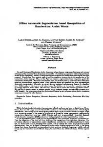
A service specification comprises a diagram expressing exchanges between the network and the connected phones, and some constraints expressing physical properties of the phones. Since we adopt a user point of view, we abstract the whole physical network and its components by a unique object, the network. We first illustrate our formalism on the example of the POTS diagram (Figure 1). The beginning of a communication involves a single phone, A. At the root node, the annotation “A : POTS” indicates that from this point, the variable A will represent a phone subscribing to POTS, and the label idle(A) specifies that A is in the idle state. Node properties are both required before messages labelling outgoing edges are sent and after messages labelling entering ones are sent. Most of the edges are labelled by a phone message and a network answer. Conventionally, a phone message such as A.call(B), begins with the phone name while a network message like start(disctone).A, ends with it. At each node, each potential future event is specified so that each possible transition is on the diagram. Whether B is 3
idle or not, there are two possible network answers to the message A.call(B). Thus there are two edges with a idle(A) A:POTS shared part labelled A.call(B). A.offhook B is introduced at this level, as start(dltone).A a subscriber to POTS. If B coremitting(A,dltone) A.onhook A.startdialing responds to an engaged equipment, then it meets the condistop(dltone).A tion ∼ idle(B) and A obtains dialing(A) idle(A) A.onhook B:POTS the line busy tone at the next A.call(B) idle(B) state (emitting(A,lbtone)). For ~ idle(B) start(rbtone).A start(rgtone).B start(lbtone ).A simplicity, we consider that diidle(A) aling an incorrect number also emitting(A,rbtone) emitting(A, lbtone ) emitting(B,rgtone) A.onhook leads to the line busy tone. NoA.onhook B.offhook tice that idle(B) and ∼ idle(B), stop(rbtone).A stop(rgtone).B stop(rgtone).B its negative, are incompatible idle(A) talking(B,A) idle(A) conditions and the transitions talking(A,B) idle(B) are deterministic. Each node is B.onhook A.onhook annotated by a number n and start(disctone).B start(disctone).A start(disctone).A an alphabetically ordered list of idle(B) idle(A) emitting(A,disctone) emitting(B,disctone) variables, the ones which are in B.onhook A.onhook its scope. Moreover, each node is implicitly prefixed by the seridle(A) idle(B) vice name POTS. On Figure 1, numbers from 1 (the root node) Figure 1: diagram of POTS to 14 (the idle(B) one) and lists of variables are given near each node. This numeration allows us to model intrinsic loop phenomena and to avoid specification redundancies. Thus, we could have replaced the node “12, (A, B)” by the alias “P OT S, 11, (B, A)”. This alias with the list (B, A) would indicate that the rôles of A and B have to be exchanged. Indeed, when B goes on hook, everything happens as if A goes on hook, except that their rôles are exchanged. All other symbols involved in the POTS diagram naturally correspond to their usual meaning. For example, the network message start(disctone).A leads to a specific tone indicating to A that there is no longer a user talking to it. By going on hook after the node 5, A enters in an idle state and do not listen to any tone. To specify services, some pieces of information are missing about state literals. A phone A cannot satisfy, in the same state, the literals talking(A, B) and idle(A). This is specified by means of axioms, called constraints, of the form talking(A, B) ⇒∼ idle(A) They allow us to restrict the set of admissible reachable states. Clearly, diagrams lack modularity: they are pertinent to describe a feature, but do not allow to specify feature integration. When 1, (A)
2,(A,B)
3,(A,B)
4,(A)
7,(A)
6,(A)
5,(A,B)
10,(A)
9,(A,B)
8,(A,B)
11,(A,B)
12,(A,B)
13,(A)
14,(B)
4
dealing with interaction detection, diagrams are convenient since a static analysis-based method only requires to compare two feature specifications.
2.2
Syntax
Among the basic data, a predefined symbol phone denotes the generic connected equipment. A data signature Σ = (S, Ω) consists of a set S of sorts such that (phone ∈ S) and a set Ω of operation definitions f : s1 × . . .×sn → s where f is an operation symbol with s1 × . . . × sn an element of3 S ∗ and s an element of S \ {phone}. Examples of sort and operation definition sets are {phone, tone} and {dialtone :→ tone, disctone :→ tone, . . .}. Connected equipments are only represented by variables in order to be anonymous and generic. We denote by V a set of variables of sort phone, provided with a total order (in fact, alphabetical). Terms with variables are built on Σ in the usual way. Specifications include some basic information: Definition 1 A feature signature Θ = (Σ, F, M, E, P ) consists of a data signature Σ = (S, Ω), a set F of feature names, a set E of phone message names (sent to the network), a set M of network message names (sent to phones), and a set P of predicate names. Each element x in F , E, M or P is provided with an arity s1 . . . sn over S ∗ , denoted by x : s1 × . . . × sn or x : ε if n = 0. For t1 , . . . , tn terms of sort resp s1 , . . . , sn and for A a phone variable, let us denote by A : f (t1 , . . . , tn ) a subscription meaning that the subscriber phone A has subscribed to f : s1 × . . . × sn in F , A.m(t1 , . . . , tn ) (resp. m(t1 , . . . , tn ).A) a phone message (resp. a network message) for m : s1 × . . . × sn ∈ E (resp. ∈ M) meaning that the phone A sends (resp. receives) the message m(t1 , . . . , tn ) to (resp. from) the network, p(t1 , . . . , tn ) for p : s1 × . . . × sn ∈ P an atomic property meaning that p(t1 , . . . , tn ) holds. A literal is either an atomic property l, or its negative denoted by ∼ l. According to the context, we call any set of literals a state condition. State Θ (V ) denotes the set of all state conditions. A system state is a state condition such that for each atomic property l, it contains either l or ∼ l. Definition 2 A call configuration is a set C = {c1 , . . . , cn } of subscriptions such that for each t of sort phone, for each subterm of any ci in C, there exists in C a subscription of the form t : f . Suppose that the Terminating Call Screening (TCS) service is introduced as TCS : phone, the subscription A : TCS(B) indicates that A subscribes 3
S ∗ denotes all the words on S (including the empty word).
5
to TCS with B as forbidden origin of incoming calls4 . {A : TCS(B), B : P OT S} is a call configuration while {A : TCS(B)} is not an acceptable one since nothing is told about the subscriptions of B. The subscription to POTS is the minimal one. Most of services are defined from this knowledge. This can be generalized by introducing a partial order relation over features. F1 ≤ F2 means5 that the specification of F2 is based on the knowledge of the one of F1 . By assumption, POTS ≤ F for all services F . To ease static analysis, diagrams are labelled rooted trees represented as finite terms. To express loop schemas or reduce diagram size, nodes are numbered, allowing alias nodes pointing at an existing numbered node. Diagrams describe system behavior by representing typical exchanges between the network and phones. They are close to Chisel diagrams ([2], [19]), specifying an alternation of messages from phones to the network and from the network to phones. Different types of label are defined for nodes and edges using an arbitrary set N (in practice IN the set of natural numbers) to systematically number nodes. Definition 3 Let us consider a feature signature Θ for a service F . • An alias for F is a pair ((G, n), (v1 , . . . , vk )) consisting of a node identifier (G, n) with n ∈ N and G ≤ F a feature, and a list (v1 , . . . , vk ) of variables in V . The set of aliases for F is denoted by Alias Θ (V ). • A state label is either a state condition or an alias for F . • An edge label is a uple made up of a set of subscriptions (possibly empty and called declaration of phones), a phone message (the only optional element, called an input), a state condition and a set of network messages S (called an output). The set of all edge labels is denoted by EdgeLabel Θ (V ). A state label is made up of literals and partly characterizes the current state of the system, while an alias is a link to a referenced node. The node identifier appearing in an alias for F has to refer to a node of a service preceding F or F itself. k is the number of variables under the scope of the referenced node. Edge labels express input and output messages leading to a system state evolution. Most of the times, outputs (network messages) occur in direct reaction to inputs (phone message) according to some conditions on the state. Conditions on edge labels are required for the given input/output message exchange but not in the source node of the transition. We can now characterize diagrams of feature specifications: 4
If one wants to express that A prevents incoming calls from both B and C, then A has to subscribe twice to the TCS service: A : TCS(B) and A : TCS(C). 5 When there is no ambiguity, we will simply identify the signature feature name to the name of the feature under specification.
6
Definition 4 A diagram D = (Node, Edge, label, I, nodelabel, edgelabel) for Θ a feature signature consists of: a rooted tree 6 , label : Node → N an injective application, I the root set of declaration of phones and nodelabel and edgelabel the labelling functions respectively from N to State Θ (V )∪Alias Θ (V ) and from Edge to EdgeLabel Θ (V ) such that each node labelled by an alias is a leaf of the rooted tree. The application label is the numeration of nodes. Occurring phone variables should be declared by a subscription. Variables used in the root node are introduced by the root set of declarations. Other variables are declared on the edge where they appear for the first time in scenarios: a kind of local variables. At each node n, the set of free variables occurring in the subdiagram sd stemming from n contains all variables which are not under the scope of a subscription declaration occurring in sd. Let us now introduce two well known services: CFB (Call Forward when dialing(A) A:POTS A.onhook A.call(B)
A:POTS dialing(A) C:POTS
A.call(B)
A.onhook
B:TCS(A) startplaying(TCSmsg ).A
B:CFB(C) idle(B) ~ idle(B) ~ idle(C) start( rbtone).A start(lbtone).A ~ idle(B)start(rbtone).A start(rgtone).B idle(C)start(rgtone).C
POTS,5,(A,B)
POTS,5,(A,C)
playing(A, TCSmsg ) A.onhook
idle(A)
POTS,10,(A) POTS,7,(A)
idle(A)
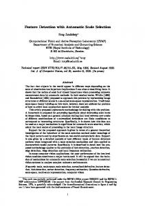
Figure 2: CFB (left) and TCS (right) diagrams.
Busy) and TCS. Figure 2 presents their diagrams. The subscription B : CF B(C) leads B to have incoming calls forwarded to the phone C when B is busy. The root node coincides with an intermediate POTS node. It ensures that the initial state of a service specification is reachable from a network with phones only subscribing to POTS. The edges labelled by A.call(B) introduce B and C with the subscriptions B : CF B(C) and C : P OT S. The diagram of CFB consists of splitting the POTS call cases: adding edges with the message A.call(B) and some conditions on the state of B and C. A set of conditions labelling an edge is a conjunction of conditions. When they label edges with the same message they have to be mutually exclusive to ensure determinism. According to the three cases, CFB is triggered or not. In particular, the first left branch stemming from the dialing(A) node is 6
A directed graph is a couple (Node, Edge) where Node and Edge are respectively the set of nodes and the set of edges (couples (source node,target node)). A rooted tree is a connected directed graph with a root: an identified node such that there is no cycle in the graph, any node being reachable from the root by a consecutive edge sequence.
7
similar to the corresponding POTS branch while the other ones are new and describe the feature execution. The branch labelled by ∼ idle(B) idle(C) means that if B is not idle and C is idle, then a communication between A and C is starting: A is listening to a ringing back tone and C to a ringing tone. There are two subdiagrams equivalent, up to some variable renaming, to the POTS subdiagram whose node identifier is (POTS, 5). To make these similarities explicit, we use aliases, graphically represented by triangles. TCS prevents incoming calls from phones chosen by the subscriber. With the subscription B : T CS(A), the POTS communication attempt in response to A.call(B) is replaced by a new refusal answer, using a specific recorded message. We define feature specifications as diagrams provided with some additional properties on system states: Definition 5 Let Θ a feature signature. A constraint is a formula l ⇒ l′ where l and l′ are literals over Θ such that phone variables occurring in l′ also occur in l. A feature specification F = (D, C) over Θ is composed of a diagram D, denoted DF , and a set C of constraints over Θ, denoted CF . Constraints are invariants on the set of reachable states. For example, talking(X, Y ) ⇒∼ dialing(Y ) is a POTS constraint specifying that a phone cannot be both talking and dialing at the same time. Each feature inherits constraints from P OT S and adds new ones, mainly when introducing new literal symbols (as playing for TCS). The restriction on the use of variables allows to deduce from a state condition all literals necessarily true w.r.t a set of constraints, which is only possible if l′ does not introduce fresh variables. We have mentioned some criteria to qualify a specification F = (DF , CF ) as well-formed. They concern the proper use of variables, alias nodes (use of variables and reference to defined nodes) and the consistent use of atomic properties within DF w.r.t constraints in CF . We will not detail these criteria here, but all of them are required to compute interactions.
3
Our method of interaction detection
Our detection method combines two major steps. The first step extracts the triggering informations of a feature F from its specification (DF , CF ). It identifies the points in DF which differ from the POTS diagram. While detecting these divergences, the algorithm collects contextual information such as subscriptions, states and triggering message. Moreover, DF is annotated with intentions. Let us illustrate this notion considering the subscriptions B : CF B(C) and C : T CS(A). When A calls B in a busy state, CFB asks the network to react as if it had received the intentional message A.call(C) 8
instead of the initial message A.call(B). But an interaction occurs with A.call(B) since the simulated message A.call(C) could originate the refusal message TCSmsg to A while CFB requires a connection between A and C. We qualify such interactions as indirect (called semantical in [22] or Sequential Action Interaction in [7]). Some other information to complete the computed intentional informations is state condition (concerning the status of idle(C)). In few words, the first step consists of computing the pertinent triggering informations given with the intentional information. The second step computes interactions by exploiting triggering information and associated intentional information. This algorithm is thus an interaction elicitation algorithm. In particular, it automatically infers the critical call configuration and triggering message leading to a given interaction.
3.1
First step : computation of triggering information
To compute the triggering information of F , we compare DF to the default diagram POTS. The exploration is done according to a breath first strategy and to the building of a variable renaming from variables of DF to the ones of DP OT S . Renaming allows to superpose the diagrams while preserving the rôles of the variables inside each one. The principles are the following ones: • We look for a node in POTS coinciding with the root node of DF , up to a variable renaming λ in order to initiate the diagram comparison. • The comparison is pursued by comparing the immediate subdiagrams. Diagram paths are recursively pairwise compared. The variable renaming λ is extended to the new encountered variables while descending the compared paths. We extract the set of paths such that the first edge of the path cannot be found in POTS. The edge source is the activation point, the edge phone message is the triggering message, the union of the edge condition and the source node label is the triggering condition, and the subdiagram linked to the edge target is the activation subdiagram. • We elicit intentional messages by looking for a network answer in POTS similar to those of the activation subdiagram. If the search is successful, the phone message at the origin of the corresponding POTS subdiagram is the intentional message we are looking for. To each intentional message is associated an intentional condition: the union of the condition labelling the corresponding POTS edge and its source node label. We also search for intentional messages inside the activation subdiagram. To conclude, triggering information is basically made up of a call configuration, a triggering message, a triggering condition, an annotated acti-
9
vation diagram7 , intentional message and condition. The information computed for CFB is synthesized in the following table. Confronting CFB with POTS identifies the CFB dialing(A) node as activation point. From this node, the diagram contains two branches sharing the A.call(B) message and the ∼ idle(B), dialing(A) condition but respectively with the idle(C) and ∼ idle(C) conditions. The triggering message is A.call(B). Computed intentional messages are in the first case A.call(C) (with the idle(C) condition) and in the second case A.call(C) (with the ∼ idle(C) condition). Call configuration A : POTS C : POTS B : CFB(C) A : POTS C : POTS B : CFB(C)
Triggering msg. A.call(B) A.call(B)
Condition ∼ idle(B) dialing(A) idle(C) ∼ idle(B) dialing(A) ∼ idle(C)
Intentional message A.call(C)
Condition
A.call(C)
∼ idle(C) dialing(A)
idle(C) dialing(A)
In the TCS diagram, the two POTS branches for the A.call(B) message are replaced by a new branch: the network sends the playing of a recorded refusal message for which any intentional message cannot be found. Call configuration A : POTSB : TCS(A)
3.2
Triggering message A.call(B)
Condition dialing(A)
Intentional msg. none
Condition none
Second step: elicitation of interactions
To detect interactions between two features F1 and F2 (possibly F1 = F2 ), we apply static analysis to their respective triggering information. Our search is decomposed into three main steps according the kind of interactions we are looking for. At first glance, there are three principal cases explaining that invocation of F1 causes an interaction with F2 . First, F1 and F2 share the same triggering message (direct interaction). Second, the intentional message associated to the triggering message of F1 coincides with the triggering message of F2 (indirect interaction). Third, the activation of F1 is likely to activate F2 via real or intentional messages. The third step simply amounts to apply in the first and second cases at each edge of the activation diagram. For i = 1, 2, let CCi , T Mi , Ci be respectively a call configuration, a triggering message and a triggering condition associated with Fi . Let IMi and ICi denote the intentional message and associated condition when they exist. The comparison begins with the search of a variable renaming λ between the two variable sets for F1 and F2 such that it unifies the (triggering or intentional) messages of F1 and F2 . It is also required that triggering conditions are compatible. It means that λ(C1 ) ∪ λ(C2 ) is a consistent state condition w.r.t. the constraints of both F1 and F2 . As soon as the comparison 7
Due to lack of space, such diagrams will be left implicit in the sequel.
10
of messages provides us with such a variable renaming, there is an interaction. An interaction is composed of a call configuration CC already defined, a triggering message T M, and a state condition T C, already computed as λ(C1 ) ∪ λ(C2 ): • Direct interactions (λ(T M1 ) = λ(T M2 )): T M = λ(T M1 ). • Indirect interactions (λ(IM1 ) = λ(T M2 ) or reciprocally). To observe an interaction, we then require that the conditions λ(IC1 ) and λ(C2 ) are consistent w.r.t. constraints of F1 and F2 . In other words, when F1 is triggered, the simulated behavior meets the triggering condition of F2 triggering. T M is the message λ(T M1 ) at the origin of the intentional message λ(IM1 ). Such an interaction can be understood as: “in the configuration CC, when F1 is triggered on the message T M1 , all happens as if the network had received the message IM1 , at the origin of an indirect F2 triggering”. We do not detail the case of indirect or direct interactions occurring with messages inside an activation diagram. We can decide whether a detected interaction is sensible or not. If after a joint triggering of F1 and F2 , the two activation diagrams are similar, then the interaction is perceived as invisible. Else, it is a visible one and there really exists a difference between service requirements. CC TM TC or
{A : POTS, B : CFB(C), B : TCS(A), C : POTS} A.call(B) {∼ idle(B), idle(C), dialing(A)}) {∼ idle(B), ∼ idle(C), dialing(A)})
CC’ TM’ TC’ or
{A : POTS, B : CFB(C), C : TCS(A), C : POTS} A.call(B) (int. message : A.call(C)) {∼ idle(B), idle(C), dialing(A)} {∼ idle(B), ∼ idle(C), dialing(A)}
The interactions between TCS and CFB are automatically computed from their diagrams and their associated constraints.
4
A case study
In this section, we present the results of a case study ordered by France Telecom (the historical French phone company), considered as a benchmark to evaluate our technique and involving three services: a voice mail service (VM), call waiting (CW) and an automatic recall service (RBF; for Ring Back when Free). They have been chosen because they were complex enough not to be considered as toy examples and not to allow experiments to be run by hand. These three services have been derived from informal specifications of France Telecom services. Our aim was to check whether the found interactions were the good ones or not, and whether all interactions were found or not. We received a real positive feedback with regard to the high level of qualitative description of interactions and with regard to the fact that our method is fully automatic,
11
without any additional knowledge given by an expert (like indications on the number of phones to consider with or without subscriptions to some services).
4.1
The three services and their triggering informations
RBF allows the subscriber A to automatically recall a phone B that was VAR A:RBF idle(A) not idle at the first VAR B:POTS idle(B) 1 called(A,B,d) A.offhook call: A is offered to currentime(1)