Complete generalization of the Ayrton-Perry formula for beam-column buckling problems JÓZSEF SZALAI1* 1
ConSteel Solutions Ltd., 1095-Hungary, Budapest, Mester utca 87.
This paper is accepted for publication in Engineering Structures on 10 October 2017
*
Corresponding author. Tel: +36 70 1998057; e-mail:
[email protected]
1
Abstract – The Ayrton-Perry (or Perry-Robertson) formula based stability resistance model (APF) is very popular in steel structural design standards. Although the original version of the model is more than 100 years old, it is still frequently used and continuously researched due to its simplicity and adaptability. The original and most widely accepted version of the APF is valid only for the flexural buckling of compression members yielding the basic formulation of the column buckling curves of several structural design codes. Recently there were more successful attempts for the extension of the APF type resistance model for other buckling modes such as torsional buckling or lateral-torsional buckling. The paper continues this research by deriving a complete closed-form universal APF type solution for steel beam-column stability problems. Rigorous mathematical solution is given for the so-called “fundamental case” which is defined by a simply supported prismatic beam-column with arbitrary cross-section subjected to uniform compression and biaxial bending. The exact interpretation and the universal form of the member slenderness, imperfection and reduction factors are presented for all possible buckling cases. The results of the paper can widen significantly the field of applicability of APF based design methods providing a theoretically consistent physical model for the beam-column stability problems.
Keywords: Ayrton-Perry formula; steel beam-column member; flexural buckling; torsional buckling; flexural-torsional buckling; lateral-torsional buckling; imperfection factor; amplification factor; second order forces; Overall Stability Design Method
2
Nomenclature Matrix-vector notations 𝑨
linear operator representing the second order stiffness matrix
𝑨𝒂𝒍𝒕
alternative form of 𝑨 for doubly symmetric cross-sections
𝑫
linear differential operator representing the first order stiffness matrix
𝑫𝟎
zero order part of 𝑫
𝑫𝟐
second order part of 𝑫
𝑭
external force vector
𝑹
resistance force vector
𝑺
internal force vector
𝑺𝑰𝑨𝒄𝒕𝒊𝒗𝒆
active part of the first order internal force vector
𝑺𝑰𝒑𝒂𝒔𝒔𝒊𝒗𝒆
passive part of the first order internal force vector
∆𝑺𝑰𝑰 𝑳𝒐𝒂𝒅
second order internal force vector increment from applied loads only
∆𝑺𝑰𝑰 𝑰𝒎𝒑
second order internal force vector increment from imperfection only
𝑼
displacement vector
𝑼𝟏
second order displacement vector due to the applied loads only
𝑼𝟐
second order displacement vector increment due to the imperfection only
𝑼𝒕𝒐𝒕 𝟐
total second order displacement vector due to the imperfection only (𝑼𝟎 +
𝑼𝟐 ) 𝑼𝟎
geometrical imperfection vector identical to a buckling mode of the system
Roman letters 𝐴
cross-section area
𝐵
internal bimoment
𝐵𝑠𝑒𝑐
bimoment resistance of the cross-section
E
elastic modulus
3
e0
lateral deflection of the compressed flange as geometric imperfection
component 𝑓𝑦
yield stress
G
shear modulus
h
height of the doubly-symmetric cross-section
𝐼𝑦 , 𝐼𝑧
second moment of inertia about the strong and weak axis
𝐼𝑤
warping moment of inertia
𝐼𝑡
St. Venant torsional constant
𝑀𝑦 , 𝑀𝑧
external or internal strong and weak axis bending moment
𝑀𝑦,𝑠𝑒𝑐 , 𝑀𝑧,𝑠𝑒𝑐 strong and weak axis bending moment resistance of the cross-section 𝑀𝑐𝑟
elastic critical bending moment for pure lateral-torsional buckling
N
external or internal compression force
Nsec
compression force resistance of the cross-section
Ncr,x
elastic critical compression force for pure torsional buckling
Ncr,y
elastic critical compression force for pure strong axis flexural buckling
Ncr,z
elastic critical compression force for pure weak axis flexural buckling
r0
radius of gyration
x,y,z
longitudinal centroidal, strong and weak axis of the member
y0,z0
position of the shear center in the principal centroidal system
u,v,w
longitudinal, strong and weak axis displacement component
u0,v0,w0
longitudinal, strong and weak axis geometrical imperfection component
𝑊𝑦 , 𝑊𝑧
section moduli about the strong and weak axis (can be elastic or plastic)
𝑊𝑤
warping section moduli (can be elastic or plastic)
Greek letters 𝛼𝑐𝑟
elastic critical load multiplication factor
𝛼𝑠𝑒𝑐
first order cross-section capacity load multiplication factor
𝛼𝑠𝑒𝑐,𝑎 , 𝛼𝑠𝑒𝑐,𝑝 first order cross-section capacity load multiplication factor for the active and passive loads respectively 4
𝛼𝑠𝑒𝑐,𝑁 , 𝛼𝑠𝑒𝑐,𝑀𝑦 , 𝛼𝑠𝑒𝑐,𝑀𝑧
first order cross-section capacity load multiplication factor
for the pure compression, strong and weak axis bending 𝛼𝑠𝑒𝑐
modified cross-section capacity load multiplication factor
𝛼𝑏
buckling resistance load multiplication factor
y,z
parameters of monosymmetry for the strong axis and weak axis asymmetry respectively
𝜂
generalized imperfection factor
𝜂
alternative form of the generalized imperfection factor
𝜆
generalized slenderness factor
𝜆̅𝑧
generalized slenderness factor for weak axis flexural buckling
𝜆̅𝑦
generalized slenderness factor for strong axis flexural buckling
𝜆̅𝐿𝑇
generalized slenderness factor for lateral-torsional buckling
𝜇
interaction parameter in the generalized imperfection factor
𝜒
generalized buckling reduction factor
𝜑
rotation about the longitudinal axis displacement component
𝜑0
rotation about the longitudinal axis geometrical imperfection component
5
1. Introduction This paper discusses the theoretically exact derivation and the consistent generalized forms of the Ayrton-Perry formula (APF) for various steel beam-column stability problems. The original APF analytically defines the load carrying capacity of a geometrically imperfect column subjected to pure compression. The formula is based on the onset of yielding in the most compressed fibre calculated from the elastic second order member forces [1]. This simple analytical model is very suitable to describe the complex mechanical behaviour of the member buckling phenomenon and to calibrate conveniently to experimental or high level numerical results, as it is demonstrated in the next section. Accordingly the APF has been adopted by several modern structural standards as the basic design model for the buckling resistance of steel members [2-5]. The first application for the purpose of standardized structural design is dated back to the early British code [6] in 1932, where supported by the experimental results of Robertson [7] the APF was introduced for the design of compressed members. Later, after the wide experimental and numerical program on column buckling the European buckling curves were established by Beer and Schulz [8] and finally the APF was used to model the multiple design buckling curves of ECCS. The basic advantage of the APF is that it can be very accurately calibrated to the experimental buckling curves by one parameter only: the imperfection factor [9]. Up to this time the APF had been used only for the modelling of flexural buckling of compression members, the fundamental problem it had been originally developed for. In 1991 it was the first time that the APF based model was proposed for a different buckling problem: in [10] it was extended for lateral-torsional buckling. However it should be noted that the authors in [10] failed to consistently derive the APF for the lateral-torsional buckling problem, thus the original form of column buckling was used and calibrated to experimental results. It is also important to see that the ECCS column buckling curves – which were established almost 40 years ago – are still unchanged and valid in the Eurocode 3 [2] and in many other design codes and proved to be accurate according to several investigations during this time. The standard design model for lateral-torsional buckling has however been modified in the later version of the Eurocode 3 [2] and is still under research due to lack of proper consistency
6
and accuracy. The main reason for this is the lack of theoretical derivation behind the valid design formula, which reveals the significance of a consistent mechanical background for the proper buckling problem. This was recognized by Chapman and Buhagiar who first derived the theoretically consistent APF for different problem than flexural buckling of compressed members: it was the torsional and flexural-torsional buckling of thin-walled members subjected to compression [11]. Later Szalai and Papp developed the theoretically consistent APF for the case of lateral-torsional buckling of beams [12] considering the buckling mode for the shape of the initial geometrical imperfections. In this work the necessary conditions were established for the consistent generalization of the APF for beam-column buckling problems. Based on these findings in [12] the APF was derived for the lateral-torsional buckling of beam-columns subjected to compression and bending considering constant compression effect. Naumes at al. [13] also applied the APF to beam-columns modelling the compressed flange as an equivalent column, and they proposed an approximate solution for non-uniform members and loading as well. Applying a similar approach recently the APF was also used to develop design model for tapered columns [14] and beams [15]. More recently a completely validated and verified new design method was proposed for the APF based resistance calculation of beam-columns [16] subjected to major axis bending and compression. Extension of the applicability of the APF is consequently useful when creating new design methods for further, specific buckling problems. The main objective of the paper is however to develop a consistent mechanical background for a new buckling design approach based on the overall elastic critical buckling analysis of complete structural models [17]. This new design approach is referred to as Overall Stability Design Method (OSDM) in this paper. The basic idea of OSDM is that it no longer separates the pure loading and buckling modes of the generally loaded members – for instance the compression and bending corresponding to flexural and lateral-torsional buckling modes – but considers the complex loads and forces evaluating the appropriate overall buckling modes. The overall buckling analysis of structural models is now available for the practical engineers by several structural design software packages and the OSDM utilizes these additional analysis results in the standard design rules for
7
member stability. Having the relevant overall buckling mode and the corresponding elastic critical load one overall slenderness and one buckling reduction factor should be calculated only. The OSDM can also be applied for not only for single, isolated members but for structural model parts or whole structural models where the overall buckling mode is dominant. A first version of this progressive and very promising design approach was published for beam-column structures by Papp [18, 19] in the 1990s. A standard design method based on these works appeared in the Hungarian Standard as an alternative procedure for the calculation of buckling resistances [20]. Later the approach was used by Müller and Sedlacek [21, 22] for the stability assessment of frame structures and a safety evaluation was also provided in order to verify its suitable reliability. Based on the latter works a standardized version of OSDM has already been published in the Eurocode 3 [2] in section 6.3.4 “General method for lateral and lateral torsional buckling of structural components” as an alternative verification method for out-of-plane buckling modes. It should be noted that all the mentioned works [18-22] and even the standard rules in Eurocode 3 [2] used only an intuitive formulation for the buckling reduction factor without any proper mechanical background. Although these formulations usually proved to be safe for specific design problems [23-26] the missing theoretical evidence and properly wide numerical or experimental verifications provide basis for the scientific criticism and confirm the need for further research of the OSDM [27]. One of the most significant drawbacks is the unjustified form of the overall buckling reduction factor. This factor is currently defined in the Eurocode 3 [2] as a derivation from the two buckling curves for pure lateral and pure lateral-torsional buckling. This solution apparently uses the APF by the form of the two different buckling curves but in a heuristic way. The consistent generalization of the APF for the proper definition of the single overall reduction factor was the subject of several works [12-13, 28-31] considering however certain buckling cases only. It is also worth to mention that the consistent APF is the theoretical base for another overall type stability design method: the Overall Imperfection Method (OIM). In this methodology the shape of the equivalent geometric imperfection is identical to one of the overall buckling shapes of the model, and the amplitude is recalculated from a relevant APF based buckling reduction factor. A
8
simple form of the OIM has already been published in the Eurocode 3 [2] for simple column buckling but recently more research studies are dealing with the generalization of the OIM to other buckling cases [32-34]. As it is clear from [34] the theoretical base for the correct amplitude definition – which is the key point of all equivalent imperfection based methods – is the existence of the proper APF for the buckling case examined. It can be stated that though the original APF is more than 100 years old but it has been continuously used and developed and is still under research in the field of standard design for member buckling problems. However up to now only specific solutions are published considering limited cases for certain members, loading and buckling forms. This paper aims to present a more comprehensive extension of the APF based on a higher level generalization and showing solutions derived for several yet unsolved buckling problems. The structure of the paper is the following: (1) the basic technique of the generalization is presented through the original simple problem of the APF for compressed members (2) then the so-called “fundamental case” is defined: it is the broadest field of problems where a closed form APF can be derived (3) the generalized APF is derived for the “fundamental case” in a universal closed form (4) the universal form of the APF is applied for specific practically significant problems, which can be regarded as sub-cases of the fundamental case. Some of the results show that the universal form includes all the known specific solutions (e.g. flexural buckling) and they can be treated as descendent of the universal form, other results present completely new solutions for important buckling problems (e.g. lateral-torsional buckling of biaxially loaded members or buckling cases of members with monosymmetric sections) (5) some specific solutions for important new cases are discussed in detail
9
2. The standard terms and form of the Ayrton-Perry formula
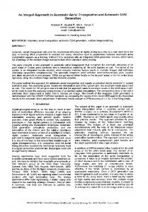
In this section the basic idea of the original APF is presented briefly and it is used for the demonstration of the main techniques for the generalization. A more detailed derivation can be found in [12] here only the key concept is presented. In Fig. 1 the basic equations of APF for compressed columns are illustrated in terms of the relationships between the compression force level (N) and the lateral displacement of the middle cross-section (v).
Figure 1.
The graphical illustration of the APF for column buckling problem
It can be well seen that the APF denotes the intersection of two curves (using the notations of [2]): (1) the second order elastic behaviour curve starting from an equivalent geometric lateral imperfection (v0,eq) and asymptotically approaching the elastic critical compression force (Ncr) as the lateral displacement is increasing:
v
1 v0,eq 1 N N cr
10
(1)
(2) the first yield criterion curve in the middle cross-section calculated from the elastic stress components from compression and second order bending, starting from the compression resistance of the cross-section (Nsec):
N Nv 1 N sec Wf y
(2)
where W is the elastic section modulus. One quite important feature of the APF should be noted here: that the intersection point can be expressed explicitly as the solution of a quadratic equation in terms of the normal force N as shown later. From this representation the basic advantage of the APF can be observed: the real buckling resistance of the member (Nb in Fig. 1) can be suitably approximated by calibrating one parameter only: the amplitude of the equivalent geometric lateral imperfection (v0,eq) which can cover the effects of all the imperfections (geometric, material, load etc.) and the partial plasticity of member as well. Eq. (1) is published first by Young [35] and it describes the relationship between the geometric imperfection and the elastic second order lateral displacement by the well-known amplification factor. This is referred to as Young’s equation. Eq. (2) is a cross-section resistance formula for compression gradually decreased by the growing bending moment induced by the increasing lateral displacement. This is referred to as section capacity equation. These two basic equations are used for the two main steps of the generalization and accordingly some properties of these equations should be underlined here: (1) in the amplification factor of the Young’s equation the quotient term in the denominator is to the first power; (2) the section capacity equation is a) explicitly expressed in terms of the first order internal force (N – in this case equal to the applied external load) b) written at the exact location of the critical cross-section (where the section utilization is the highest) which is known a priori (at midspan of the member); c) linear in terms of the first order internal force N and of the second order displacement v. 11
These properties are important requirements for the consistent derivation of the APF for any other problem. Since the generalization aims at arriving to a solution for complex beam-column problems subjected to various loads the first obvious step is the introduction of different load multiplication factors (LMFs). These LMFs represent the conservative load(s) by a single scalar value at different stages of loading of the member: – elastic critical LMF: at this load level the ideal, perfectly straight member
𝛼𝑐𝑟
reaches its critical state (bifurcation point) with regards to its elastic stability – first order cross-section capacity LMF: at this load level the most utilized
𝛼𝑠𝑒𝑐
(critical) cross-section of the ideal, perfectly straight member reaches its full utilization with regards to its elastic (or linearized plastic) resistance (excluding all the second order effects) – buckling resistance LMF: at this load level the real, (geometrically and
𝛼𝑏
materially) imperfect member reaches its elastic-plastic buckling capacity In terms of the parameters of the compressed member problem these LMFs can be written as 𝛼𝑐𝑟 =
𝑁𝑐𝑟 𝑁
, 𝛼𝑠𝑒𝑐 =
𝑁𝑠𝑒𝑐 𝑁
and 𝛼𝑏 =
𝑁𝑏 𝑁
(see Fig. 1). It is to be noted that the APF
is to determine the unknown 𝛼𝑏 from the known values of 𝛼𝑐𝑟 and 𝛼𝑠𝑒𝑐 . Using these notations further the Young’s equation and the section capacity equation can be reformulated at the buckling load level 𝛼𝑏 (which is to be determined): 𝑣 = 1−𝛼
1
𝑣0,𝑒𝑞
(3)
𝑣=1
(4)
𝑏 ⁄𝛼𝑐𝑟
𝛼𝑏 𝛼𝑠𝑒𝑐
𝛼
+𝛼𝑏
𝐴
𝑠𝑒𝑐 𝑊
Substituting Eq. (3) into Eq. (4) and multiplying by (𝛼𝑐𝑟 − 𝛼𝑏 )⁄𝛼𝑠𝑒𝑐 one can obtain the following expression: 𝛼
2
𝛼
𝛼
𝛼
(𝛼 𝑏 ) + 𝛼 𝑏 (−1 − 𝛼 𝑐𝑟 − 𝛼 𝑐𝑟 𝑠𝑒𝑐
𝑠𝑒𝑐
𝑠𝑒𝑐
𝑠𝑒𝑐
𝐴 𝑊
𝛼
𝑣0,𝑒𝑞 ) + 𝛼 𝑐𝑟 = 0 𝑠𝑒𝑐
(5)
Eq. (8) is the standard form of the APF in terms of the introduced LMFs which is a quadratic equation for unknown 𝛼𝑏 (and accordingly for the 𝑁𝑏 ) having explicit solution. Introducing three more scalar factors (notations taken form the EC3 [2]): 𝐴
𝜂 = 𝑊 𝑣0,𝑒𝑞
– generalized imperfection factor
12
𝛼
𝜆 = √ 𝛼𝑠𝑒𝑐 𝑐𝑟
𝛼
𝜒=𝛼𝑏
– generalized slenderness factor of the member – buckling reduction factor denoting the reduction in the section capacity
𝑠𝑒𝑐
due to the second order effects from the equivalent geometrical imperfection Eq. (5) can be written in the following form: 1
1
1
𝜒 2 + 𝜒 (−1 − 𝜆2 − 𝜆2 𝜂) + 𝜆2 = 0
(6)
This form is identical to the one obtained in [12] as the fundamental quadratic form of the APF using the standard notation of EC3 [2]. The solution of this equation yields the wellknown form of the column buckling curves defined in EC3 [2]: 𝜒=
1 𝛷+√𝛷2 −𝜆2
1
where 𝛷 = 2 (1 + 𝜂 + 𝜆2 )
(7)
The aim of the paper is to generalize the above equations using the presented LMFs and the introduced additional factors (imperfection, slenderness and reduction) arriving at the basic quadratic form of the APF identical to Eq. (7) for a broader field of buckling problems called: the fundamental case. Based on the findings of this section about the nature of the APF the fundamental case of beam-column buckling problems where the quadratic form of Eq. (7) can be explicitly derived is defined by the following conditions: C1
The examined single member is prismatic with any cross-section (symmetric, monosymmetric or asymmetric)
C2
The loads are conservative, uniform compression and uniform biaxial bending
C3
There are simple supports at both ends of the member. The very important consequence is that the boundary conditions for buckling are consistent, i.e. the shapes of the displacement components of the buckling mode are identical having the maximum amplitude in the middle of the member.
Furthermore during the solution of the fundamental case the usual approximations are made:
The material is homogeneous, isotropic and linear elastic up to the section capacity (even if it is the full plastic resistance)
13
In the section capacity equation the normal stress resultants are considered only (compression, bending moments and bimoment) the shear stress resultants are neglected
The second order equilibrium equations are linearized in terms of the displacement components
The displacements and rotations are small
Bernoulli’s hypotheses apply
The coordinate system and rotations follow the right hand rule
3. Solution of the fundamental case
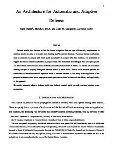
The governing differential equations of equilibrium of imperfect beam-columns describing the fundamental case of buckling problems can be found in several textbooks for instance in [36] and takes the following form: 2u ( x) N x 2 2 w( x) M y 0 EI y M y ( M z Ny0 ) ( x) 0 ( x) N w( x) w0 ( x) x 2 2 v( x) M z 0 EI z M z ( M y Nz0 ) ( x) 0 ( x) N v( x) v0 ( x) x 2 3 ( x) ( x) ( x) 0 ( x) M x 0 EI w GI t M y y M z z Nr02 3 x x x x N 0 EA
(8-11)
v( x) v0 ( x) w( x) w0 ( x) ( M y Nz0 ) ( M z Ny0 ) x x x x
where the notations are explained at the beginning of the paper and illustrated in Fig.2. Eqs. (8-11) describe the equilibrium of the external and internal forces along the member for axial force (N), bending moments about the strong (My) and weak (Mz) axis and torsional moment (Mx) respectively. For the sake of simpler derivation of the section capacity equation Eq. (11) is reformed by integrating and applying the boundary conditions to express the equilibrium of the bimoment along the member: 2 ( x) GI t ( x) M y y M z z Nr02 ( x) 0 ( x) x 2 ( M y Nz 0 )v( x) v0 ( x) ( M z Ny0 )w( x) w0 ( x)
B 0 EI w
14
(12)
The boundary conditions for the displacement functions are the following: 𝑤(0) = 𝑤(𝐿) = 0 ; 𝑣(0) = 𝑣(𝐿) = 0 ; 𝜑(0) = 𝜑(𝐿) =
Figure 2.
𝜕2 𝑤(0) 𝜕𝑥 2
𝜕2 𝑣(0) 𝜕𝑥 2
𝜕2 𝜑(0) 𝜕𝑥 2
=
=
=
𝜕2 𝑤(𝐿) 𝜕𝑥 2
𝜕2 𝑣(𝐿) 𝜕𝑥 2
𝜕2 𝜑(𝐿) 𝜕𝑥 2
𝑀𝑦
= − 𝐸𝐼
𝑦
𝑀
= 𝐸𝐼𝑧
(13-15)
𝑧
=0
The coordinate system, displacements and the end moments of the crosssection
From Eqs. (13-15) it follows that the imperfections cannot add additional bending moments and bimoment at the ends since the supports are pinned and forked. In order to achieve a general form Eqs. (8-12) are formalized introducing the following vector and matrix terms: 0 𝑢(𝑥) 𝑁 (𝑥) 𝑤 𝑤(𝑥) −𝑀𝑦 0 𝑼= ; 𝑼𝟎 = [ (𝑥) ] ; 𝑭 = [ ] 𝑣 𝑣(𝑥) 𝑀𝑧 0 𝜑0 (𝑥) [𝜑(𝑥)] 0
15
𝜕2 𝐸𝐴 2 𝜕𝑥
𝑫=
𝐸𝐼𝑦
𝜕2 𝜕𝑥 2
[
𝐸𝐼𝑧
𝜕2 𝜕𝑥 2
0 𝑁
𝑨= [
𝑀𝑧 − 𝑁𝑦0
𝑁 𝑀𝑦 + 𝑁𝑧0
𝜕2 𝐸𝐼𝑤 2 − 𝐺𝐼𝑡 ] 𝜕𝑥 𝑀𝑧 − 𝑁𝑦0 𝑀𝑦 + 𝑁𝑧0 −𝑀𝑦 𝛽𝑦 + 𝑀𝑧 𝛽𝑧 + 𝑁𝑟02 ]
Using these vectors and matrices Eqs. (8-12) can be written in matrix form: (𝑫 + 𝑨) ∙ 𝑼 = 𝑭 − 𝑨 ∙ 𝑼𝟎
(16)
Eq. (16) shows the basic form of the fundamental case. The general form of the APF is obtained from this basic form in two steps: (1) first the generalized Young’s equation is derived from Eq. (16) and (2) the section capacity equation is expanded in the second step considering the conditions described in the previous section. 3.1 Generalization of the Young’s equation
Since D and A are linear operators the solution U of Eq. (16) can be written as the sum of the solutions for the following two equations (U = U1 + U2): (𝑫 + 𝑨) ∙ 𝑼𝟏 = 𝑭
(17a)
(𝑫 + 𝑨) ∙ 𝑼𝟐 = −𝑨 ∙ 𝑼𝟎
(17b)
where U1 is the second order displacement function due to the applied loads and U2 is the second order displacement function due to the imperfections. It is important to note here that these two components of the total displacement can be separated and calculated independently only if the second order equilibrium equations are linearized in terms of the displacement components as it is assumed in the previous section. However no further requirements should be applied, so for all the linearized second order systems which can be written in the form of Eq. (16) the following generalized Young’s equation is valid. Since Eq. (17a) is independent of the imperfection it is not covered by the APF accordingly the Young’s equation can be derived from Eq. (17b) only. As it is clearly proved in [12] it is essential to consider that the shape of the imperfection 𝑼𝟎 is identical 16
to a buckling mode of the system accordingly it should satisfy the following generalized eigenvalue equation: (𝑫 + 𝛼𝑐𝑟 𝑨) ∙ 𝑼𝟎 = 𝟎
(18)
where 𝛼𝑐𝑟 is the associated eigenvalue representing the elastic critical LMF. Multiplying Eq. (17b) by (𝛼𝑐𝑟 − 1): (𝛼𝑐𝑟 − 1)(𝑫 + 𝑨) ∙ 𝑼𝟐 = −𝛼𝑐𝑟 𝑨 ∙ 𝑼𝟎 + 𝑨 ∙ 𝑼𝟎
(19)
Using Eq. (18) it can be written that −𝛼𝑐𝑟 𝑨 ∙ 𝑼𝟎 = 𝑫 ∙ 𝑼𝟎
(20)
So Eq. (19) becomes: (𝛼𝑐𝑟 − 1)(𝑫 + 𝑨) ∙ 𝑼𝟐 = (𝑫 + 𝑨) ∙ 𝑼𝟎
(21)
and the solution for the second order displacement from imperfections having a shape of a buckling mode is: 𝑼𝟐 = 𝛼
1
𝑐𝑟 −1
𝑼𝟎
(22)
And the total second order displacement from the initial imperfection is: 𝑼𝒕𝒐𝒕 𝟐 = 𝑼𝟎 + 𝛼
1
𝑐𝑟
𝑼 = −1 𝟎
1 1−
1 𝛼𝑐𝑟
𝑼𝟎
(23)
This is the generalized form of the Young’s equation written originally for compressed members in the form of Eq. (1) expressing the well-known amplification relationship between the total second order displacement and the initial imperfection. The existence of this relationship is essential for the generalization of the APF accordingly all the requirements which were assumed for this derivation – especially the linearized second order system of Eq. (16) – are necessary to consider. The solution of the complete fundamental case of Eq. (16) describing the total deformation is the sum of the two displacement components: 𝑼 = 𝑼𝟏 + 𝑼𝟐 = 𝑼𝟏 + 𝛼
1
𝑐𝑟 −1
𝑼𝟎
(24)
3.2 Generalization of the section capacity equation
The generalized section capacity equation is started from the internal second order forces acting along the member from the total deformation of Eq. (24): 17
𝜕2 𝑢
𝐸𝐴 𝜕𝑥 2
𝑁 𝐼𝐼 𝜕2 𝑤 𝐸𝐼 𝑦 𝑀 𝜕𝑥 2 𝑺 = [ 𝑦] = = 𝑫𝟐 𝑼 𝜕2 𝑣 𝑀𝑧 𝐸𝐼𝑧 𝜕𝑥 2 𝐵 𝜕2 𝜑 𝐸𝐼 𝑤 [ 𝜕𝑥 2 ]
(25)
where the linear differential operator is practically divided according to the followings: 𝑫 = 𝑫𝟎 + 𝑫𝟐 𝜕2 𝐸𝐴 2 𝜕𝑥
𝑫𝟐 = [
(26) 𝜕2 𝐸𝐼𝑦 2 𝜕𝑥
0 𝐸𝐼𝑧
𝜕2 𝜕𝑥 2
2
𝜕 𝐸𝐼𝑤 2 ] 𝜕𝑥
; 𝑫𝟎 = [
0
]
0 −𝐺𝐼𝑡
The internal second order forces can be composed of three different components: (1) the first order internal forces, (2) the increment in the second order internal forces caused by the combined loads and (3) the increment in the second order internal forces caused by the imperfections. Moreover it is necessary to separate two kinds of loads – and accordingly two kinds of internal forces for the further derivations:
active in buckling: this load induces directly the examined type of buckling
passive in buckling: this load is mechanically independent of the examined type of buckling but has additional utilization effect
For instance in the case of a member subjected to compression and (in-plane) bending if the relevant failure mode is flexural buckling in the plane of the bending moment the compression is the active load and the bending is the passive load. Mathematically the deformed shape of the member calculated from the active loads is orthogonal to the buckling shape, while the deformed shape calculated from the passive loads has parallel component(s) in the buckling shape. The APF is naturally taking into account only the active loads but the passive load effects should also be considered somehow in a complete resistance model as will be shown in the next section. Accordingly the total second order internal forces can be written as: 𝑰𝑰 𝑰 𝑺 = 𝑺𝑰𝑨𝒄𝒕𝒊𝒗𝒆 + ∆𝑺𝑰𝑰 𝑰𝒎𝒑 + 𝑺𝑷𝒂𝒔𝒔𝒊𝒗𝒆 + ∆𝑺𝑳𝒐𝒂𝒅
(27)
18
where the first two terms are the subject of the APF and third and fourth term (if they are existing) should be considered as an initial condition of the system since they are independent of the buckling. The second term of Eq. (27) can be written as: ∆𝑺𝑰𝑰 𝑰𝒎𝒑 = 𝑫𝟐 𝑼𝟐 = 𝑫𝑼𝟐 − 𝑫𝟎 𝑼𝟐 = −𝑨
1 1−
1 𝛼𝑐𝑟
𝑼𝟎 − 𝑫𝟎 𝛼
1
𝑐𝑟 −1
𝑼𝟎
(28)
where the following relationship derived from Eq. (22) inserted into Eq. (17b) was used: (𝑫 + 𝑨) ∙
1
1
𝛼𝑐𝑟
𝑐𝑟
𝑼 = −𝑨 ∙ 𝑼𝟎 → 𝛼 −1 𝟎
𝑫𝑼𝟎 = − −1
1 1−
1 𝛼𝑐𝑟
𝑨𝑼𝟎
(29)
Finally Eq. (27) takes the following form (combining the buckling independent last two terms and omitting the negative sign from Eq. (28) since in the section capacity equation all the load effects are added): 𝑺 = 𝑺𝑰𝑨𝒄𝒕𝒊𝒗𝒆 + (𝑨
1 1 1− 𝛼𝑐𝑟
𝑼𝟎 + 𝑫𝟎 𝛼
1
𝑼𝟎 ) + 𝑺𝑰𝑰 𝑷𝒂𝒔𝒔𝒊𝒗𝒆
𝑐𝑟 −1
(30)
From the internal second order forces the linear section capacity equation can be written at the maximum utilization position in general as follows: [𝑹𝑻 𝑺]𝒎𝒂𝒙 = 1
(31)
where the vector of the associated section resistances was introduced: 1 𝑁𝑠𝑒𝑐 1 𝑀𝑦,𝑠𝑒𝑐 𝑹= 1 𝑀𝑧,𝑠𝑒𝑐 1 [ 𝐵𝑠𝑒𝑐 ] It should be noted that the section resistances can be elastic or plastic as well, the linear form of Eq. (31) should only be kept for the APF derivation. In the fundamental case it is evident that the position of the maximum section utilization is at the middle of the member where the amplitudes of the imperfection components are the largest; all the subsequent equations are written to this cross-section. Inserting Eq. (30) into Eq. (31) the section capacity equation can be written as: 𝑹𝑻 𝑺𝑰𝑨𝒄𝒕𝒊𝒗𝒆 + (𝑹𝑻 𝑨
1 1 1− 𝛼𝑐𝑟
𝑼𝟎 + 𝑹𝑻 𝑫𝟎 𝛼
1
𝑐𝑟 −1
𝑼𝟎 ) + 𝑹𝑻 𝑺𝑰𝑰 𝑷𝒂𝒔𝒔𝒊𝒗𝒆 = 1 19
(32)
Introducing the following two LMFs: 𝑹𝑻 𝑺𝑰𝑨𝒄𝒕𝒊𝒗𝒆 = 𝛼
1
𝑠𝑒𝑐,𝑎
; 𝑹𝑻 𝑺𝑰𝑰 𝑷𝒂𝒔𝒔𝒊𝒗𝒆 = 𝛼
1
𝑠𝑒𝑐,𝑝
Eq. (32) has the following final form: 1 𝛼𝑠𝑒𝑐,𝑎
+ (𝑹𝑻 𝑨
1 1−
1 𝛼𝑐𝑟
𝑼𝟎 + 𝑹𝑻 𝑫𝟎 𝛼
1
𝑐𝑟 −1
𝑼𝟎 ) = (1 − 𝛼
1
𝑠𝑒𝑐,𝑝
)
(33)
The right hand side of Eq. (33) expresses that the available section capacity for the buckling resistance is decreased by the utilization effect of passive second order loads.
3.3 The generalized form of the APF for the fundamental case
Now the final task is to derive the generalized form of the APF using the section capacity equation of Eq. (33). As it was stated in Section 2 it is very important to see again that the APF is to determine the unknown buckling resistance load LMF 𝛼𝑏 from the known values of 𝛼𝑐𝑟 , 𝛼𝑠𝑒𝑐,𝑎 and 𝛼𝑠𝑒𝑐,𝑝 calculated at the actual design load level. For the solution the section capacity equation should be formulated at the buckling resistance load level 𝛼𝑏 similar to Eq. (4) accordingly the relevant terms of Eq. (33) is expressed at the buckling resistance LMF as follows: 𝛼𝑠𝑒𝑐,𝑏 =
𝛼𝑠𝑒𝑐,𝑎 𝛼𝑏
; 𝛼𝑐𝑟,𝑏 =
𝛼𝑐𝑟 𝛼𝑏
; 𝑨𝒃 = 𝛼𝑏 𝑨
(34-36)
Since the term 𝛼𝑠𝑒𝑐,𝑝 is independent of the buckling this term is constant in the derivation as a fixed initial condition for the solution. Eq. (33) can be written at the buckling resistance load level using Eqs. (34-36): 𝛼𝑏 𝛼𝑠𝑒𝑐,𝑎
+ 𝛼𝑏 (𝑹𝑻 𝑨𝑼𝟎
1 𝛼 1− 𝑏 𝛼𝑐𝑟
+ 𝑹𝑻 𝑫𝟎 𝑼𝟎 𝛼
1
𝑐𝑟 −𝛼𝑏
) = (1 − 𝛼
1
𝑠𝑒𝑐,𝑝
)
(37)
Introducing a new section capacity LMF including the fix effect of the passive second order loads: 𝛼𝑠𝑒𝑐 = 𝛼𝑠𝑒𝑐,𝑎 (1 − 𝛼
1
𝑠𝑒𝑐,𝑝
)
(38)
Eq. (37) can be rewritten:
20
𝛼𝑏 𝛼𝑠𝑒𝑐
𝛼
+ 𝛼 𝑏 𝛼𝑠𝑒𝑐,𝑎 (𝑹𝑻 𝑨𝑼𝟎 𝑠𝑒𝑐
Multiplying Eq. (39) by 𝛼𝑐𝑟 𝛼𝑏 2 𝛼𝑠𝑒𝑐
−
𝛼𝑏2 2
𝛼𝑠𝑒𝑐
+
𝛼𝑐𝑟 𝛼𝑏 2
𝛼𝑠𝑒𝑐
1 𝛼 1− 𝑏
𝛼𝑐𝑟
𝛼𝑐𝑟 −𝛼𝑏 𝛼𝑠𝑒𝑐
+ 𝑹𝑻 𝑫𝟎 𝑼𝟎 𝛼
1
𝑐𝑟 −𝛼𝑏
)=1
(39)
: 1
𝛼𝑠𝑒𝑐,𝑎 (𝑹𝑻 𝑨𝑼𝟎 + 𝑹𝑻 𝑫𝟎 𝑼𝟎 𝛼 ) = 𝑐𝑟
𝛼𝑐𝑟 −𝛼𝑏
(40)
𝛼𝑠𝑒𝑐
We introduce again the slightly modified reduction factor, slenderness (compared to those introduced in Section 2) and a generalized form of the imperfection factor: 𝛼
𝛼
1
𝜒 = 𝛼 𝑏 ; 𝜆 = √ 𝛼𝑠𝑒𝑐 ; 𝜂 = 𝛼𝑠𝑒𝑐,𝑎 (𝑹𝑻 𝑨𝑼𝟎 + 𝑹𝑻 𝑫𝟎 𝑼𝟎 𝛼 ) 𝑠𝑒𝑐
𝑐𝑟
𝑐𝑟
(41-43)
It can be seen that the slenderness and the reduction factor is dependent of the passive second order load effects also but the imperfection factor – which is connected purely to buckling – is only dependent on the active load effects as it will be demonstrated in the subcases in the next chapter. Finally the general form of the APF based quadratic equation for the reduction factor can be written by substituting Eq. (41-43) into Eq. (40): 1
1
1
𝜒 2 + 𝜒 (−1 − 𝜆2 − 𝜆2 𝜂) + 𝜆2 = 0 This simple form is completely identical to Eq. (6) which is the standard quadratic form of the APF accordingly its solution yields the reduction factor of Eq. (7) identical to the well-known form of column buckling curves defined in EC3 [2]. Eqs. (41-43) however represent the universal mechanical meaning of the inside parameters of the formula considering a much wider range of buckling problems covered by the fundamental case. These are the basic equations used in the next section to derive the consistent APF for several important specific problems.
4. The sub-cases of the fundamental case In this section the parameters of the three basic factors of the generalized APF defined in Eqs. (41-43) are written and discussed in detail for specific buckling problems which can be considered as sub-cases of the fundamental case. Some of them have already known solution; these cases are presented here in order to demonstrate that the solutions can be derived from the general Eqs. (41-43). There are however several unsolved specific but
21
practically important problems presented. The consistent APF based solutions of these cases are completely new results and can be the suitable bases for the development of efficient stability design rules. In the subsequent equations only the relevant loading and imperfection components of the specific case are inserted into Eqs. (41-43) all the terms and vector/matrix components are omitted which have zero values. 4.1 Members with doubly symmetric cross-sections
If the cross-section is doubly symmetric the basic equilibrium equations of Eqs. (8-12) take a simpler form considering that y0 = z0 = y = z = 0: 2u ( x) N x 2 2 w( x) M y 0 EI y M y M z ( x) 0 ( x) N w( x) w0 ( x) x 2 2 v( x) M z 0 EI z M z M y ( x) 0 ( x) N v( x) v0 ( x) x 2 3 ( x) ( x) v( x) v0 ( x) w( x) w0 ( x) M x 0 EI w GI t M y Mz 3 x x x x x x N 0 EA
B 0 EI w
2 ( x) GI t ( x) Nr02 ( x) 0 ( x) M y v( x) v0 ( x) M z w( x) w0 ( x) x 2
(44-48) The matrix and vector terms in the imperfection factors can be written as:
0 𝑁
𝑨= [
𝑀𝑧
𝑁 𝑀𝑦
1 𝐴𝑓𝑦 1 𝑊𝑦 𝑓𝑦 𝑀𝑧 ; 𝑹 = 𝑀𝑦 1 2 𝑁𝑟0 ] 𝑊𝑧 𝑓𝑦 1 [𝑊𝑤 𝑓𝑦 ]
where the section properties in the resistance vector can be elastic or plastic as well. Moreover an alternative form for bimoment arising from the second order displacements due to the imperfection (𝑼𝟐 in Eq.(17b)) can be written if the lateral displacement v is nonzero: 22
EI w
2 2 ( x) 2 v2 ( x) 2 2 ( x) I w EI z x 2 x 2 2 v2 ( x) I z
(49)
2 ( x) I w M y 2 ( x) 0 ( x) N v2 ( x) v0 ( x) 2 2 v2 ( x ) I z
This alternative form can lead to significantly simplified and mechanically more transparent equations; the main steps of the derivation of these are presented further in this section considering doubly symmetric cross-section. Since the shape of the buckling mode components are identical as stated in the definition of the fundamental case in condition C1, accordingly the second order displacement components have also identical shape, so it can be written: 𝜕2 𝜑2 (𝑥) 𝜕2 𝑣2 (𝑥)
=
𝜑2 (𝑥) 𝑣2 (𝑥)
=
𝜑0
(50)
𝑣0
Using Eqs. (49-50) an alternative form for A can be introduced: 0 𝑁
𝑨𝒂𝒍𝒕 =
𝑁 𝜑0 𝐼𝑤 𝑁 𝑣0 𝐼𝑧
[
𝑀𝑧 𝑀𝑦 𝜑0 𝐼𝑤 𝑀𝑦 𝑣0 𝐼𝑧 ]
and accordingly Eq. (17b) can be written in the following alternative form: (𝑫𝟐 + 𝑨𝒂𝒍𝒕 ) ∙ 𝑼𝟐 = −𝑨𝒂𝒍𝒕 ∙ 𝑼𝟎
(51)
Important to notice that the above equation uses 𝑫𝟐 instead of 𝑫 which makes the derivation easier. After some manipulations similar to those presented in Section 3.1 and 3.2 one can arrive to the alternative form of the basic the section capacity equation of Eq. (33): 1 𝛼𝑠𝑒𝑐,𝑎
+ 𝑹𝑻 𝑨𝟐 𝑼𝟎
1 1−
1 𝛼𝑐𝑟
= (1 − 𝛼
1
𝑠𝑒𝑐,𝑝
)
(52)
using a similar relationship defined in Eq.(29): (𝑫𝟐 + 𝑨𝒂𝒍𝒕 ) ∙
1 𝛼𝑐𝑟 −1
𝑼𝟎 = −𝑨𝒂𝒍𝒕 ∙ 𝑼𝟎 → 𝛼
1
𝑐𝑟 −1
𝑫𝟐 𝑼𝟎 = −
1 1−
1 𝛼𝑐𝑟
𝑨𝒂𝒍𝒕 𝑼𝟎
(53)
And finally the new form of the imperfection factor: 𝜂 = 𝛼𝑠𝑒𝑐,𝑎 𝑹𝑻 𝑨𝒂𝒍𝒕 𝑼𝟎
(54)
Eq.(54) is completely identical to Eq.(43) for doubly symmetric cross-sections but can lead to significantly simpler equations as will be shown later. It should be noted that A = Aalt in 23
the buckling cases where there is no torsional displacements (for instance pure flexural buckling) except for the case of pure torsional buckling of compressed members where Aalt has no meaning since the absence of lateral displacement. In the next subsections both forms (Eq.(43) and Eq.(54)) of the imperfection factor are presented where relevant. The derived APF terms for doubly symmetric cross-sections are summarized in Table 1. Table 1. Fundamental cases for doubly symmetric cross-sections
4.1.1 Pure strong or weak axis flexural buckling of compressed members
This case is the original problem and was presented in Section 2. The well-known terms are obtained again for the weak axis buckling case in the following: 𝑁 0 𝑰 0 𝑼𝟎 = [𝑣 ] ; 𝑺𝑨𝒄𝒕𝒊𝒗𝒆 = [ 0 ] ; 𝑺𝑰𝑰 𝑷𝒂𝒔𝒔𝒊𝒗𝒆 = 𝟎 0 0 0 0 24
𝛼𝑠𝑒𝑐,𝑎 = 𝛼𝑠𝑒𝑐 =
𝐴𝑓𝑦 1 𝑁𝑐𝑟.𝑧 = ; 𝛼 = 𝑐𝑟 𝑰 𝑁 𝑁 𝑹𝑻 𝑺𝑨𝒄𝒕𝒊𝒗𝒆 𝐴
𝜂 = 𝛼𝑠𝑒𝑐,𝑎 (𝑹𝑻 𝑨𝑼𝟎 ) = 𝑣0 𝑊
(55)
𝑧
The strong axis buckling case can be written similarly inserting the appropriate imperfection component (𝑤0 ) and axis for the elastic critical force (𝑁𝑐𝑟.𝑦 ) and section modulus (𝑊𝑦 ).
4.1.2 Pure torsional buckling of compressed members
In pure torsional buckling mode the twist of the member is the only displacement component in the imperfection and the bimoment is the only second order effect. Accordingly the factors of the APF are the following: 0 𝑁 0 𝑰 𝑼𝟎 = [ 0 ] ; 𝑺𝑨𝒄𝒕𝒊𝒗𝒆 = [ 0 ] ; 𝑺𝑰𝑰 𝑷𝒂𝒔𝒔𝒊𝒗𝒆 = 0 0 𝜑0 0 𝛼𝑠𝑒𝑐,𝑎 = 𝛼𝑠𝑒𝑐 =
𝐴𝑓𝑦 1 𝑁𝑐𝑟.𝑥 = ; 𝛼 = 𝑐𝑟 𝑁 𝑁 𝑹𝑻 𝑺𝑰𝑨𝒄𝒕𝒊𝒗𝒆 1
𝑟2𝐴
𝐺𝐼𝑡
𝜂 = 𝛼𝑠𝑒𝑐,𝑎 (𝑹𝑻 𝑨𝑼𝟎 + 𝛼 𝑹𝑻 𝑫𝟎 𝑼𝟎 ) = 𝜑0 𝑊0 − 𝜑0 𝑁 𝑐𝑟
𝑤
𝐴
𝑐𝑟.𝑥 𝑊𝑤
(56)
4.1.3 Pure lateral-torsional buckling of members in bending
In pure lateral-torsional buckling mode the two displacement components of the imperfection are the lateral displacement and the twist of the member, and the two second order effects are the weak axis bending and the bimoment. Accordingly the factors of the APF are the following: 0 0 𝑀 𝑼𝟎 = [ 𝑣0 ] ; 𝑺𝑰𝑨𝒄𝒕𝒊𝒗𝒆 = [ 𝑦 ] ; 𝑺𝑰𝑰 𝑷𝒂𝒔𝒔𝒊𝒗𝒆 = 0 0 0 𝜑0 0 𝛼𝑠𝑒𝑐,𝑎 = 𝛼𝑠𝑒𝑐 =
𝑊𝑦 𝑓𝑦 1 𝑀𝑐𝑟 = ; 𝛼 = 𝑐𝑟 𝑀𝑦 𝑀𝑦 𝑹𝑻 𝑺𝑰𝑨𝒄𝒕𝒊𝒗𝒆 25
1
𝑊𝑦
𝑊𝑦
𝑤
𝑧
𝐺𝐼 𝑊𝑦
𝜂 = 𝛼𝑠𝑒𝑐 , 𝑎 (𝑹𝑻 𝑨𝑼𝟎 + 𝛼 𝑹𝑻 𝑫𝟎 𝑼𝟎 ) = 𝑣0 𝑊 + 𝜑0 𝑊 − 𝜑0 𝑀 𝑡 𝑐𝑟
𝑊𝑦
𝑊𝑤
𝑊𝑦 𝜑0 𝐼𝑤
𝜂 = 𝛼𝑠𝑒𝑐,𝑎 𝑹𝑻 𝑨𝒂𝒍𝒕 𝑼𝟎 = 𝜑0 𝑊 + 𝜑0 𝑊 𝑧
𝑐𝑟
𝑤
(57) (58)
𝑣0 𝐼𝑧
Eq. (57) is completely the same form as it was derived in [12]. The identity of Eq. (57) and Eq. (58) can be proved by considering that in pure lateral-torsional buckling the quotient of the buckling mode components can be written as
𝜑0 𝑣0
=
𝑁𝑐𝑟,𝑧 𝑀𝑐𝑟
according to [12] and
applying it to Eq. (58). However Eq. (58) can be further simplified using the following relationship for doubly symmetric cross-sections: 1 𝐼𝑤 𝑊𝑤 𝐼𝑧
1 ℎ
=𝑊
𝑧
(59)
2
and one can arrive to the following form: 𝑊𝑦
𝑊𝑦 ℎ 𝑁𝑐𝑟,𝑧
𝜂 = 𝜑0 𝑊 + 𝜑0 𝑊
𝑧 2 𝑀𝑐𝑟
𝑧
= 𝑣0
𝑁𝑐𝑟,𝑧 𝑊𝑦 𝑀𝑐𝑟 𝑊𝑧
𝑊𝑦 ℎ 𝑁𝑐𝑟,𝑧
+ 𝜑0 𝑊
𝑧 2 𝑀𝑐𝑟
𝑊𝑦 𝑁𝑐𝑟,𝑧
= 𝑒0 𝑊
𝑧
𝑀𝑐𝑟
(60)
where e0 is the lateral deflection of the compressed flange, see Fig. 3: ℎ
𝑒0 = 𝑣0 + 2 𝜑0
(61)
The form of Eq. (60) is identical to the one derived in [29] for lateral-torsional buckling and as it was shown his solution is identical to the one obtained in [12] in the form of Eq. (57). From calibration point of view however this alternative form of Eq. (60) is more convenient including one imperfection displacement component only with a strong mechanical meaning.
Figure 3.
The imperfection components of the doubly symmetric cross-section
26
4.1.4 Flexural buckling of members subjected to compression and in-plane bending
In the previous cases there were active loads only in the present case there are active (compression) and passive load (bending) types together. This case has no general APF solution yet in the literature. Two different cases should be considered: strong axis flexural buckling with strong axis bending and weak axis flexural buckling with weak axis bending. The former is presented; the latter can be obtained in the same way considering the other axis. Factors of the APF: 0 0 𝑁 𝑀𝐼𝐼 𝑤 𝑼𝟎 = [ 0 ] ; 𝑺𝑰𝑨𝒄𝒕𝒊𝒗𝒆 = [ 0 ] ; 𝑺𝑰𝑰 =[ 𝑦] 𝑷𝒂𝒔𝒔𝒊𝒗𝒆 0 0 0 0 0 0 𝐴𝑓𝑦 𝑊𝑦 𝑓𝑦 1 1 𝛼𝑠𝑒𝑐,𝑎 = 𝑻 𝑰 = ; 𝛼𝑠𝑒𝑐,𝑝 = 𝑻 𝑰𝑰 = 𝐼𝐼 𝑁 𝑀𝑦 𝑹 𝑺𝑨𝒄𝒕𝒊𝒗𝒆 𝑹 𝑺𝑷𝒂𝒔𝒔𝒊𝒗𝒆 𝛼𝑠𝑒𝑐 = 𝛼𝑠𝑒𝑐,𝑎 (1 −
1 𝛼𝑠𝑒𝑐,𝑝
)=
𝐴𝑓𝑦 𝑀𝑦𝐼𝐼 𝑁𝑐𝑟.𝑦 (1 − ) ; 𝛼𝑐𝑟 = 𝑁 𝑊𝑦 𝑓𝑦 𝑁
𝐴
𝜂 = 𝛼𝑠𝑒𝑐,𝑎 (𝑹𝑻 𝑨𝑼𝟎 ) = 𝑤0 𝑊
(62)
𝑦
In the above factors the bending moment 𝑀𝑦𝐼𝐼 includes the second order effect from the combined loads of compression and bending only but excludes the second order effect from imperfection. The imperfection factor defined by Eq. (62) is identical to Eq. (55) (only in a different buckling plane) since the buckling is induced by the compression only, the inplane bending moment effect is considered in the slenderness through the modified section capacity LMF 𝛼𝑠𝑒𝑐 . 4.1.5 Lateral-torsional buckling of members subjected to bending and compression
This case is solved in [12] in a special way assuming the compression as a fixed initial condition. Using the derived general equations in this section the same problem is solved to conservative loading, where the first order compression and bending are the active load effects and the second order bending moment increment – due to the combined loads – is the passive load effect. The APF has the following terms and factors: 27
𝑁 0 0 𝐼𝐼 𝑀 ∆𝑀 𝑦 𝑼𝟎 = [ 𝑣0 ] ; 𝑺𝑰𝑨𝒄𝒕𝒊𝒗𝒆 = [ 𝑦 ] ; 𝑺𝑰𝑰 = [ ] 𝑷𝒂𝒔𝒔𝒊𝒗𝒆 0 0 0 𝜑0 0 0 1
𝛼𝑠𝑒𝑐,𝑎 = 𝑹𝑻𝑺𝑰
1
=
1
𝑨𝒄𝒕𝒊𝒗𝒆
𝛼𝑠𝑒𝑐,𝑁 𝛼𝑠𝑒𝑐,𝑀𝑦
1
𝛼𝑠𝑒𝑐 = 𝛼𝑠𝑒𝑐,𝑎 (1 −
𝛼𝑠𝑒𝑐,𝑝
𝜂 = 𝛼𝑠𝑒𝑐,𝑎 (𝑹𝑻 𝑨𝑼𝟎 + 𝛼
=
1
+
1
1
𝑀𝑦 𝑁 + 𝐴𝑓𝑦 𝑊𝑦 𝑓𝑦
1
)=
𝑀𝑦 𝑁 + 𝐴𝑓𝑦 𝑊𝑦 𝑓𝑦
; 𝛼𝑠𝑒𝑐,𝑝 = 𝑹𝑻 𝑺𝑰𝑰
=
𝑷𝒂𝒔𝒔𝒊𝒗𝒆
∆𝑀𝑦𝐼𝐼
Δ𝑀𝑦𝐼𝐼 (1 − ) 𝑊𝑦 𝑓𝑦
1 𝑻 𝑹 𝑫𝟎 𝑼𝟎 ) = 𝛼𝑐𝑟
𝐴
𝛼
𝐴
𝑊𝑦
𝑊𝑦
𝑤
𝑧
𝐺𝐼𝑡 𝛼𝑠𝑒𝑐,𝑎
= 𝛼 𝑠𝑒𝑐,𝑎 (𝑣0 𝑊 + 𝜑0 𝑟02 𝑊 ) + 𝛼 𝑠𝑒𝑐,𝑎 (𝑣0 𝑊 + 𝜑0 𝑊 ) − 𝜑0 𝑊 𝑠𝑒𝑐,𝑁
𝑊𝑦 𝑓𝑦
𝑧
𝑤
𝑠𝑒𝑐,𝑀𝑦
𝑤 𝑓𝑦
𝛼𝑐𝑟
(63)
𝜂 = 𝛼𝑠𝑒𝑐,𝑎 𝑹𝑻 𝑨𝒂𝒍𝒕 𝑼𝟎 = 𝛼
𝐴
𝐴 𝜑0 𝐼𝑤 ) 𝑤 𝑣0 𝐼𝑧
= 𝛼 𝑠𝑒𝑐,𝑎 (𝑣0 𝑊 + 𝑣0 𝑊 𝑠𝑒𝑐,𝑁
𝑧
𝑊𝑦
𝛼
𝑊𝑦 𝜑0 𝐼𝑤 ) 𝑤 𝑣0 𝐼𝑧
+ 𝛼 𝑠𝑒𝑐,𝑎 (𝜑0 𝑊 + 𝜑0 𝑊 𝑠𝑒𝑐,𝑀𝑦
𝑧
(64)
Both Eq. (63) and Eq. (64) are new results for the lateral-torsional buckling of beamcolumns. In Eq. (63) one can discover the imperfection terms of pure flexural buckling, torsional buckling and lateral-torsional buckling defined in Eqs. (55-57) multiplied by the suitable proportion factors considering the ratio between the compression and bending. Eq. (64) can be further simplified taking into account the following relationship (based on the relationship defined in [12]): 𝛼𝑐𝑟 𝑁 𝜑0 1 𝑁𝑐𝑟,𝑧 − 𝛼𝑐𝑟 𝑁 1 𝑁𝑐𝑟,𝑧 1 − 𝑁𝑐𝑟,𝑧 √ = √ = √ = 𝑣0 𝑟0 𝑁𝑐𝑟,𝑥 − 𝛼𝑐𝑟 𝑁 𝑟0 𝑁𝑐𝑟,𝑥 1 − 𝛼𝑐𝑟 𝑁 𝑁𝑐𝑟,𝑥 =𝑟
𝑁𝑐𝑟,𝑧
0 √𝑁𝑐𝑟,𝑧 𝑁𝑐𝑟,𝑥
1−𝛼𝑐𝑟 𝑁/𝑁𝑐𝑟,𝑧
√1−𝛼
𝑐𝑟 𝑁/𝑁𝑐𝑟,𝑥
=
𝑁𝑐𝑟,𝑧 𝑀𝑐𝑟
1−𝛼𝑐𝑟 𝑁/𝑁𝑐𝑟,𝑧
√1−𝛼
𝑐𝑟 𝑁/𝑁𝑐𝑟,𝑥
=
𝑁𝑐𝑟,𝑧 𝑀𝑐𝑟
𝜇
(65)
In the above equation we introduced a new factor: 1−𝛼 𝑁/𝑁
𝜇 = √1−𝛼𝑐𝑟𝑁/𝑁𝑐𝑟,𝑧 𝑐𝑟
(66)
𝑐𝑟,𝑥
Introducing Eq. (59), Eq. (61) and Eq. (65) into Eq. (64) the alternative form of the imperfection factor can be written as:
28
𝜂=
𝑊𝑦 𝑁𝑐𝑟,𝑧 𝑊𝑦 ℎ 𝑁𝑐𝑟,𝑧 𝛼𝑠𝑒𝑐,𝑎 𝐴 𝐴 ℎ 𝛼𝑠𝑒𝑐,𝑎 (𝑣0 + 𝜑0 )+ (𝑣0 𝜇 + 𝜑0 𝜇) = 𝛼𝑠𝑒𝑐,𝑁 𝑊𝑧 𝑊𝑧 2 𝛼𝑠𝑒𝑐,𝑀𝑦 𝑊𝑧 𝑀𝑐𝑟 𝑊𝑧 2 𝑀𝑐𝑟
𝛼
𝐴
𝑊𝑦 𝑁𝑐𝑟,𝑧
𝛼
= 𝛼 𝑠𝑒𝑐,𝑎 𝑒0 𝑊 + 𝛼 𝑠𝑒𝑐,𝑎 𝑒0 𝑊 𝑠𝑒𝑐,𝑁
𝑧
𝑠𝑒𝑐,𝑀𝑦
𝑧
𝑀𝑐𝑟
𝜇
(67)
From Eq. (64) it can be seen that the two terms connected with the compression and bending effect have identical form as it was presented for the pure cases in Eq. (55) and Eq. (60) with the modifying factor defined in Eq. (66). This means that the theoretically correct imperfection factor for the lateral-torsional buckling of beam-columns subjected to compression and strong axis bending can be composed from the imperfection factors of the pure flexural buckling of columns and pure lateral-torsional buckling of beams by this special interpolation. It is a very important result from the point of view of calibration and development of simple design formula for beam-columns. It should be noted that in a proposal for design formula for lateral-torsional buckling of beam-columns in [16] a different interpolation is used for the imperfection factor based however on heuristic concept. Using Eq. (67) the theoretically correct interpolation can be used for further design methods.
4.1.6 Lateral-torsional buckling of members subjected to biaxial bending
In this completely unsolved case the first order strong axis bending is the active load effect and the second order weak axis bending and the second order bimoment increment are the passive load effects, accordingly the following factors can be written: 0 0 0 𝑀 0 0 𝑼𝟎 = [ 𝑣 ] ; 𝑺𝑰𝑨𝒄𝒕𝒊𝒗𝒆 = [ 𝑦 ] ; 𝑺𝑰𝑰 = [ 𝐼𝐼 ] 𝑷𝒂𝒔𝒔𝒊𝒗𝒆 𝑀 0 0 𝑧 𝜑0 ∆𝐵 𝐼𝐼 0
𝛼𝑠𝑒𝑐,𝑎 =
𝑊𝑦 𝑓𝑦 1 1 1 = ; 𝛼 = = 𝑠𝑒𝑐,𝑝 𝑰 𝑰𝑰 𝑀𝑦 𝑹𝑻 𝑺𝑨𝒄𝒕𝒊𝒗𝒆 𝑹𝑻 𝑺𝑷𝒂𝒔𝒔𝒊𝒗𝒆 𝑊𝑧 𝑓𝑦 𝑊𝑤 𝑓𝑦 + 𝑀𝑧𝐼𝐼 ∆𝐵𝐼𝐼
𝛼𝑠𝑒𝑐 = 𝛼𝑠𝑒𝑐,𝑎 (1 −
1 𝛼𝑠𝑒𝑐,𝑝
)=
𝑊𝑦 𝑓𝑦 𝑀𝑧𝐼𝐼 ∆𝐵 𝐼𝐼 (1 − ( + )) ; 𝑀𝑦 𝑊𝑧 𝑓𝑦 𝑊𝑤 𝑓𝑦
29
𝛼𝑐𝑟 =
𝑀𝑐𝑟 𝑀𝑦 1
𝑊𝑦
𝑊𝑦
𝑤
𝑧
𝐺𝐼 𝑊𝑦
𝜂 = 𝛼𝑠𝑒𝑐,𝑎 (𝑹𝑻 𝑨𝑼𝟎 + 𝛼 𝑹𝑻 𝑫𝟎 𝑼𝟎 ) = 𝑣0 𝑊 + 𝜑0 𝑊 − 𝜑0 𝑀 𝑡 𝑐𝑟
𝑐𝑟
(68)
𝑊𝑤
𝑊𝑦 𝑁𝑐𝑟,𝑧
𝜂 = 𝛼𝑠𝑒𝑐,𝑎 𝑹𝑻 𝑨𝒂𝒍𝒕 𝑼𝟎 = 𝑒0 𝑊
(69)
𝑀𝑐𝑟
𝑧
The imperfection factors are identical to that of pure lateral-torsional buckling of Eq. (57) and Eq. (60) since the buckling is induced by the strong axis bending only, the weak axis bending effect is considered in the slenderness through the modified section capacity LMF 𝛼𝑠𝑒𝑐 . 4.1.7 Lateral-torsional buckling of members subjected to biaxial bending and compression
This is the most complex case with interaction between lateral and lateral-torsional buckling caused by the active loads of compression and strong axis bending and additional passive load effects from the second order strong axis bending and bimoment increment and the total second order weak axis bending. The terms of the APF are the following: 0 𝑁 0 𝐼𝐼 ∆𝑀 𝑀 𝑦 𝑼𝟎 = [ 𝑣0 ] ; 𝑺𝑰𝑨𝒄𝒕𝒊𝒗𝒆 = [ 𝑦 ] ; 𝑺𝑰𝑰 = [ ] 𝑷𝒂𝒔𝒔𝒊𝒗𝒆 0 0 𝑀𝑧𝐼𝐼 𝜑0 0 ∆𝐵 𝐼𝐼 1
𝛼𝑠𝑒𝑐,𝑎 = 𝑹𝑻𝑺𝑰
1
=
𝑨𝒄𝒕𝒊𝒗𝒆
𝛼𝑠𝑒𝑐 = 𝛼𝑠𝑒𝑐,𝑎 (1 −
1
𝛼𝑠𝑒𝑐,𝑁 𝛼𝑠𝑒𝑐,𝑀𝑦
1 𝛼𝑠𝑒𝑐,𝑝
𝜂 = 𝛼𝑠𝑒𝑐,𝑎 (𝑹𝑻 𝑨𝑼𝟎 + 𝛼
+
=
1
)=
1
1
𝑀𝑦 𝑁 + 𝐴𝑓𝑦 𝑊𝑦 𝑓𝑦
1 𝑀𝑦 𝑁 + 𝐴𝑓𝑦 𝑊𝑦 𝑓𝑦
; 𝛼𝑠𝑒𝑐,𝑝 = 𝑹𝑻 𝑺𝑰𝑰
𝑷𝒂𝒔𝒔𝒊𝒗𝒆
1
𝑊𝑧 𝑓𝑦 𝑊𝑤 𝑓𝑦 + 𝐼𝐼 + ∆𝐵𝐼𝐼 ∆𝑀𝐼𝐼 𝑀𝑧 𝑦
∆𝑀𝑦𝐼𝐼 𝑀𝑧𝐼𝐼 ∆𝐵𝐼𝐼 (1 − ( + + )) 𝑊𝑦 𝑓𝑦 𝑊𝑧 𝑓𝑦 𝑊𝑤 𝑓𝑦
1 𝑻 𝑹 𝑫𝟎 𝑼𝟎 ) = 𝛼𝑐𝑟
𝐴
𝐴
𝛼
𝑊𝑦
𝑊𝑦
𝑤
𝑧
𝐺𝐼𝑡 𝛼𝑠𝑒𝑐,𝑎
= 𝛼 𝑠𝑒𝑐,𝑎 (𝑣0 𝑊 + 𝜑0 𝑟02 𝑊 ) + 𝛼 𝑠𝑒𝑐,𝑎 (𝑣0 𝑊 + 𝜑0 𝑊 ) − 𝜑0 𝑊 𝑠𝑒𝑐,𝑁
= 𝑊𝑦 𝑓𝑦
𝑧
𝜂 = 𝛼𝑠𝑒𝑐,𝑎 𝑹𝑻 𝑨𝒂𝒍𝒕 𝑼𝟎 =
𝑤
𝑠𝑒𝑐,𝑀𝑦
𝛼𝑠𝑒𝑐,𝑎 𝐴 𝑒 𝛼𝑠𝑒𝑐,𝑁 0 𝑊𝑧
+
𝑊𝑦 𝑁𝑐𝑟,𝑧 𝛼𝑠𝑒𝑐,𝑎 𝑒 𝜇 𝛼𝑠𝑒𝑐,𝑀𝑦 0 𝑊𝑧 𝑀𝑐𝑟
30
𝑤 𝑓𝑦
𝛼𝑐𝑟
(70) (71)
The imperfection factors are identical to that of Eq. (63) and Eq. (67) since the buckling is induced by the compression and strong axis bending only, the weak axis bending effect is considered in the slenderness through the modified section capacity LMF 𝛼𝑠𝑒𝑐 . 4.2 Members with monosymmetric cross-sections
Two different cases should be considered (Fig. 4.): (1) Weak axis asymmetry: the axis of symmetry is the strong axis (e.g. channel, sigma profiles) where z0 = y = 0 and y0 ≠ 0 ; z ≠ 0; (2) Strong axis asymmetry: the axis of symmetry is the weak axis (e.g. monosymmetric I profile) where y0 = z = 0 and z0 ≠0 ; y ≠ 0. In the next two sections these two cases are examined and the factors of the proper APF are presented. Since the way of derivation of the factors are identical to the case of doubly symmetric sections only the initial matrix terms are shown and the final form of the factors are illustrated in Tables 2 and 3.
Figure 4.
The two cases of monosymmetry
31
4.2.1 Weak axis asymmetry
Table 2. Fundamental cases for monosymmetric cross-sections with weak axis asymmetry: z0 = y = 0 and y0 ≠ 0; z ≠ 0
In the case of weak axis asymmetry the eccentricity between the centre of gravity and the shear centre lies on the strong axis causing second order weak axis bending effect from the compression (effect of y0) and additional second order bimoment effect from the weak axis bending and the rotation (Wagner-effect of z). There are accordingly two major issues connected with the possible buckling modes:
For the basic case of pure compression (the compressive force is applied in the centre of gravity) there are two possible buckling modes only: the weak axis flexural buckling and the strong axis flexural-torsional buckling. Latter one is caused by the additional second order weak axis bending effect. However since the 32
weak axis flexural buckling is always gives lower critical load this is usually the relevant mode for compression members.
Because of the importance of the Wagner-effect in case of pure weak axis bending (causing quite significant second order bimoment) there is reasonable possibility for lateral-torsional buckling failure due to weak axis bending so this case is also presented (Mcr,z in Table 2). However it should be noted that the sign of the Wagnereffect depends on the sign of the applied weak axis bending. So for instance in the case of a channel section if the web is under compression (value of 𝛽𝑧 is positive) the Wagner-term is positive strengthening the torsional stiffness of the section and eliminating the possibility for lateral-torsional buckling, but if the flanges are compressed (value of 𝛽𝑧 is negative) the negative Wagner-term decreases the torsional stiffness and the lateral-torsional buckling becomes a relevant failure mode.
The matrix and vector terms in the imperfection factors can be written as:
0 𝑁
𝑨= [
𝑀𝑧 − 𝑁𝑦0
𝑁 𝑀𝑦
1 𝐴𝑓𝑦 1 ̅̅̅̅ 𝑊𝑦 𝑓𝑦 𝑀𝑧 − 𝑁𝑦0 ; 𝑹 = 𝑀𝑦 1 2 ̅̅̅̅𝑧 𝑓𝑦 𝑁𝑟0 + 𝑀𝑧 𝛽𝑧 ] 𝑊 1 ̅̅̅̅ [𝑊𝑤 𝑓𝑦 ]
The top-lined section moduli in the resistance vector should consider the sign of the bending moments and bimoment, and should accordingly be calculated at the most compressed point of the cross-section. This is however not always a straightforward problem since the significance of second order moments can be very different depending on the elastic critical LMF and the ratio of the displacement and section rotation components in the buckling shape. In such situations it is advisable to examine all the possible extreme points evaluating the APF factors in these points and taking the most unfavourable one. When the plastic resistances are used however there are no such problems since the plastic section moduli are not depending on the section points.
33
Table 2 shows the cross-section capacity LMFs and the imperfection factors for the different load cases and possible buckling modes using the above matrix and vector terms and the same way of derivation as it is presented for doubly symmetric sections. It can be seen that the cross-section capacity LMFs have the same form as in Table 1 for doubly symmetric sections except that in the case of weak axis symmetry the weak axis bending can cause lateral-torsional buckling so the Mz is always an active load effect when . The imperfection factors include the additional section parameters of y0 and z as it was explained. Table 2 gives the complete APF solution for the fundamental case of members of monosymmetric sections with weak axis symmetry.
4.2.2 Strong axis asymmetry
Table 3. Fundamental cases for monosymmetric cross-sections with strong axis asymmetry: y0 = z = 0 and z0 ≠0; y ≠ 0
In the case of strong axis asymmetry the eccentricity between the centre of gravity and the shear centre lies on the weak axis causing second order strong axis bending effect from the compression (effect of z0) and additional second order bimoment effect from the strong axis bending and the rotation (Wagner-effect of y). In this case of monosymmetry the only 34
difference in the possible buckling modes compared to the case of doubly symmetric sections is the flexural-torsional buckling mode for pure compression instead of the pure weak axis lateral and pure torsional modes. Accordingly in a member with a section of strong axis symmetry usually the relevant buckling mode for compression is the flexuraltorsional buckling. The matrix and vector terms in the imperfection factors can be written as:
0 𝑁
𝑨= [
𝑀𝑧
𝑁 𝑀𝑦 + 𝑁𝑧0
1 𝐴𝑓𝑦 1 ̅̅̅̅ 𝑀𝑧 𝑊𝑦 𝑓𝑦 ; 𝑹 = 𝑀𝑦 + 𝑁𝑧0 1 2 ̅̅̅̅ 𝑁𝑟0 − 𝑀𝑦 𝛽𝑦 ] 𝑊𝑧 𝑓𝑦 1 ̅̅̅̅ [𝑊 𝑤 𝑓𝑦 ]
Here we use also the top-lined section moduli in the resistance vector considering the sign of the bending moments and bimoment as in the previous section. Table 2 shows the crosssection capacity LMFs and the imperfection factors for the different load cases and possible buckling modes using the above matrix and vector terms and the same way of derivation as it is presented for doubly symmetric sections. It can be seen that the cross-section capacity LMFs have completely identical form as in Table 1 for doubly symmetric sections. The imperfection factors include the additional section parameters of z0 and y as it was explained. Important to note again that since the y factor is a signed sectional property depending on the sign of the strong axis bending (which flange is under compression) this term can increase or reduce the value of the relevant imperfection factors. Accordingly when the larger flange is under compression y factor takes positive value (increasing the torsional stiffness of the section) the imperfection factor has a lower value, when the smaller flange is under compression the imperfection factor is larger. Also it should be noticed that the combined loads of compression and strong axis bending causing lateral torsional buckling is again a special case. Considering that the flexural-torsional buckling due to compression has a buckling shape with a twist in the cross-section producing always bigger lateral displacement in the smaller flange it is again very important which flange is
35
under compression due to the bending. If the bending causes compression in the larger flange (which is more usual) then the pure lateral-torsional buckling shape has an opposite section twist component so with a certain amount of bending the elastic critical load and the resistance can be even increased by the stabilizing effect of the tension in the smaller flange. If the smaller flange is compressed due to the bending, then the twist components have the same sign and the second order effects are added. This phenomenon is included in the imperfection factor by the presented y factor and by the relative values of the buckling shape components v0 and . Table 3 gives the complete APF solution for the fundamental case of members of monosymmetric sections with strong axis symmetry.
4.3 Members with asymmetric cross-sections
This is the most complex instance of the fundamental case including both pairs of asymmetry parameters. Accordingly all the pure loads are active load effects the passive load effects are the second order increments only. Moreover in general all the pure load cases have associated buckling modes involving all the three displacement components w0, v0 and 0. Since the detailed description of the terms belonging to specific buckling modes at pure load cases are very similar to the ones presented in the previous sections here only the most complex interaction case with all the three loads are shown. The factors of the APF are the following: 0 𝑁 0 ∆𝑀𝑦𝐼𝐼 𝑀 𝑤 𝑼𝟎 = [ 𝑣 0 ] ; 𝑺𝑰𝑨𝒄𝒕𝒊𝒗𝒆 = [ 𝑦 ] ; 𝑺𝑰𝑰 = [ ] 𝑷𝒂𝒔𝒔𝒊𝒗𝒆 0 𝑀𝑧 ∆𝑀𝑧𝐼𝐼 𝜑0 0 ∆𝐵 𝐼𝐼 1
𝛼𝑠𝑒𝑐,𝑎 = 𝑹𝑻𝑺𝑰
𝑨𝒄𝒕𝒊𝒗𝒆
𝛼𝑠𝑒𝑐,𝑝 =
1
=
1
1
+
1
𝛼𝑠𝑒𝑐,𝑁 𝛼𝑠𝑒𝑐,𝑀𝑦 𝛼𝑠𝑒𝑐,𝑀𝑧
1 𝑹𝑻 𝑺𝑰𝑰 𝑷𝒂𝒔𝒔𝒊𝒗𝒆
𝛼𝑠𝑒𝑐 = 𝛼𝑠𝑒𝑐,𝑎 (1 −
+
=
=
1 𝑀𝑦 𝑁 𝑀 + + 𝑧 𝐴𝑓𝑦 𝑊𝑦 𝑓𝑦 𝑊𝑧 𝑓𝑦
;
1 𝑊𝑦 𝑓𝑦 𝑊𝑧 𝑓𝑦 𝑊𝑤 𝑓𝑦 + + ∆𝑀𝑦𝐼𝐼 ∆𝑀𝑧𝐼𝐼 ∆𝐵 𝐼𝐼
1 𝛼𝑠𝑒𝑐,𝑝
)=
∆𝑀𝑦𝐼𝐼 ∆𝑀𝑧𝐼𝐼 ∆𝐵𝐼𝐼 1 (1 − ( + + )) 𝑀𝑦 𝑊𝑦 𝑓𝑦 𝑊𝑧 𝑓𝑦 𝑊𝑤 𝑓𝑦 𝑁 𝑀𝑧 + + 𝐴𝑓𝑦 𝑊𝑦 𝑓𝑦 𝑊𝑧 𝑓𝑦 36
𝜂 = 𝛼𝑠𝑒𝑐,𝑎 (𝑹𝑻 𝑨𝑼𝟎 + 𝛼
𝐴
1 𝑻 𝑹 𝑫𝟎 𝑼𝟎 ) = 𝛼𝑐𝑟
𝐴
𝐴
𝐴𝑦
𝐴𝑧
0 0 = 𝛼 𝑠𝑒𝑐,𝑎 (𝑤0 ̅̅̅̅̅ + 𝑣0 ̅̅̅̅ + 𝜑0 𝑟02 ̅̅̅̅̅ − 𝑤0 ̅̅̅̅̅ + 𝑣0 ̅̅̅̅̅ − 𝜑0 𝑊 𝑊 𝑊 𝑊 𝑊 𝑠𝑒𝑐,𝑁
𝛼𝑠𝑒𝑐,𝑎 𝛼𝑠𝑒𝑐,𝑀𝑦
𝑦
𝑧
̅̅̅̅̅ 𝑊𝑦
̅̅̅̅̅ 𝑊𝑦
𝑤
𝑧
(𝑣0 ̅̅̅̅̅ + 𝜑0 ̅̅̅̅ − 𝜑0 𝑊 𝑊
𝑤
̅̅̅̅̅ ̅̅̅̅ 𝑊𝑦 𝛽𝑦 𝛼𝑠𝑒𝑐,𝑎 𝑊𝑧 ) + (𝑣 0 ̅̅̅̅̅ ̅̅̅̅̅ 𝑊𝑤 𝛼𝑠𝑒𝑐,𝑀𝑧 𝑊𝑤
𝑤
̅̅̅̅ 𝑊
+ 𝜑0
𝑧 + 𝜑0 ̅̅̅̅̅ + 𝜑0 𝑊 𝑦
𝐴𝑧0 ) ̅̅̅̅ 𝑊 𝑧
+
̅̅̅̅ 𝑊𝑧 𝛽𝑧 )− ̅̅̅̅̅ 𝑊𝑤
𝛼𝑠𝑒𝑐,𝑎
𝐺𝐼
𝑡 𝜑0 ̅̅̅̅̅ 𝑊 𝑓
𝑤
𝐴𝑦0 ̅̅̅̅̅ 𝑊 𝑦
𝑤 𝑦
(72)
𝛼𝑐𝑟
From Eq. (72) all the previously presented form of imperfection factors belonging to different special cases can deduced by neglecting the unnecessary terms, accordingly this form can be considered as the basic and most extensive description of the imperfection factor of the APF for the fundamental case.
5. Discussion
The presented results establish a consistent theoretical base for the development and calibration of Ayrton-Perry type standard resistance formulae for a wide range of buckling problems of beam-columns. The complete verification of the strength and applicability of the equations obtained (by comparison with extensive test results or numerical simulations) cannot be the purpose of this paper since it should involve a deep calibration process for the imperfection factor. This type of research was successfully done recently for some subcases: lateral-torsional buckling of beams in [31] and beam-columns in [16, 34] based on a previous theoretical work of the author [12]. These results proved the high level of mechanical transparency and flexibility of the APF making it suitable to develop powerful standard design rules for buckling resistance calculation. Accordingly the main goal of the discussion of the present results is to provide some examples for this verification process showing the applicability of the derived APFs, explaining more in detail some of the new features and clarify the limitations. In the following a recommended procedure for the APF based OSDM is considered for checking the member buckling problem. The general steps of the recommended calculations are the following (valid for the fundamental case): (1) Calculation of the first and second order internal forces and moments (N, My, Mz, B) in the midst of the member 37
(2) Calculation of the relevant overall buckling mode, the associated elastic critical LMF (cr) and the normalized buckling components in the midst of the member (v0N, w0N, 0N) (3) Analysing the load case and the buckling mode and determination of the proper buckling case from Tables 1-3 (4) Calculation of the section capacity LMFs (𝛼𝑠𝑒𝑐,𝑁 , 𝛼𝑠𝑒𝑐,𝑀𝑦 , 𝛼𝑠𝑒𝑐,𝑀𝑧 , 𝛼𝑠𝑒𝑐,𝑎 , 𝛼𝑠𝑒𝑐,𝑝 , 𝛼𝑠𝑒𝑐 ) and the overall slenderness (𝜆) from Eq. (42) (5) Determination of the calibrated suitable amplitude for the buckling mode based imperfection components (v0, w0, 0) (6) Calculation of the imperfection factor (𝜂 or 𝜂̅ ) from Eq. (43), the overall reduction factor (𝜒) from Eq. (7) and the buckling resistance LMF (𝛼𝑏 ) from Eq. (41) (7) The final check on the characteristic overall buckling resistance (without any safety factor) is as follows: 𝛼𝑏 = 𝜒𝛼𝑠𝑒𝑐 = 𝜒𝛼𝑠𝑒𝑐,𝑎 (1 − 𝛼
1
𝑠𝑒𝑐,𝑝
)≥1
(73)
In the calculation process Steps (1-2) are pure mechanical calculations available in several software products, Step (5) is the result of the mentioned calibration and verification process and Steps (3-4, 6-7) are calculations according to the equations derived in this paper. Since the calibrated amplitudes of Step (5) are not available yet for all the cases in the forthcoming examples it is always shown which value is taken for the amplitudes or for the imperfection factor. It is important to see that the calculation of the exact resistance value (where 𝛼𝑏 = 1) requires an iterative process since the nonlinearity of Eq. (73) caused by the effect of the second order passive load LMF 𝛼𝑠𝑒𝑐,𝑝 which depends on the actual load level and modifies the slenderness. However when a certain situation is checked, Eq. (73) clearly shows the adequacy of the buckling resistance in one step. The calibration process resulting in the imperfection amplitudes of Step (5) is practically started with the simpler pure buckling cases. For members with doubly symmetric crosssections it has been done for pure flexural buckling for long [7-9] and the resulted imperfection factor is used in the EC3 [2]. The pure lateral-torsional buckling is a more complex case; an APF based calibration process is presented in [31]. In order to obtain a
38
complete solution applicable for OSDM of members with doubly symmetric cross-sections the solutions for pure cases should be amended by two novel approaches:
in-plane effects can be handled by the proposed strategy with active and passive loads,
the interaction of the pure buckling cases can be modelled by Eq. (67) as a special combination of the solutions for the pure cases.
The discussion of these will be presented in the next two sections. Finally in order to study the effect of asymmetry in the cross-section the buckling of members with monosymmetric cross-sections is discussed.
5.1 Members subjected to active and passive loads
One of the main results of the paper is the mechanically consistent solution strategy for the two sources of second order effects (from imperfections and combined (in-plane) loading) by the separation of active and passive loads. This is an important deficiency in the present OSDM rules in the Eurocode 3 [2] which is not valid for in-plane buckling modes, does not include the effect of weak axis bending with out-of-plane buckling modes and heuristically propose to consider all second order in-plane effect in the section capacity LMF (denoted as 𝛼𝑢𝑙𝑡.𝑘 ) for the out-of-plane buckling modes for the sake of safety. The simplest case for the demonstration of the proposed APF solution is the flexural buckling of compressed column with in-plane bending moment, this case is described in Section 4.1.4 and the relevant factors are shown in Table 1 in rows number 5 and 6. For the example case of strong axis flexural buckling of a member subjected to compression and in-plane strong axis bending the equality of Eq. (73) can be written as follows: 𝜒
𝐴𝑓𝑦 𝑁
𝑀𝑦𝐼𝐼
(1 − 𝑊
𝑦 𝑓𝑦
) = 1 or
𝑁 𝜒𝑁𝑝𝑙
𝑀𝑦𝐼𝐼
+𝑀
𝑝𝑙,𝑦
=1
(74)
with the overall slenderness from Eq. (42): 𝑁𝑝𝑙 (1−
𝜆=√
𝑀𝐼𝐼 𝑦 ) 𝑀𝑝𝑙,𝑦
(75)
𝑁𝑐𝑟,𝑦
39
Eq. (74) is similar to an intuitive, linear interaction form for adding two utilization effects the novelty is the formulation of the slenderness in Eq. (75). It expresses the mechanically proved fact that increasing the in-plane utilization effect (passive load) will decrease the slenderness due to the lower available section capacity for the compression effect (active load). In order to demonstrate this difference two other forms are compared to Eqs. (74-75): 𝑀𝑦𝐼
𝑁 𝜒𝑁𝑝𝑙
+𝑀
𝑝𝑙,𝑦
𝑀𝑦𝐼𝐼
𝑁 𝜒𝑁𝑝𝑙
+𝑀
𝑝𝑙,𝑦
𝑁
= 1 and 𝜆 = √𝑁 𝑝𝑙
(76)
𝑐𝑟,𝑦
𝑁
= 1 and 𝜆 = √𝑁 𝑝𝑙
(77)
𝑐𝑟,𝑦
In both forms of Eqs. (76-77) the slenderness – and accordingly the reduction factor as well as the first term of the linear interaction equation – is not depending on the in-plane bending effect, and while in Eq. (76) the first order bending moment is used in the linear interaction form in Eq. (77) the second order bending moment is taken. All the three forms are evaluated for the following example:
Member length: L = 19,2 m (𝜆̅𝑦 = 1,0)
Cross-section: IPE500; material: S235
Figure 5.
The different interaction forms for flexural buckling of members subjected to compression and in-plane bending moment
40
Figure 6.
The proposed formula compared to numerical results [37] for flexural buckling of members subjected to compression and in-plane bending moment
For the imperfection factor the APF based calibrated form for compression members of the EC3 [2] is used corresponding to the buckling curve “a”. The results are shown by the interaction curves in Fig. 5. It can be seen that Eq. (76) is a simple linear interaction of the first order effects resulting a straight line, while Eq. (77) shows the usual concave curve due to the in-plane second order effects. The proposed form of Eqs. (74-75) lies between these two curves because of the new form for the slenderness as explained. In Fig. 6 the proposed form is compared to numerical simulation results taken from [37] and it can be seen that these results are absolutely verifies the accuracy of the proposed form. The other typical case for the active and passive loads is the lateral-torsional buckling of members subjected to biaxial bending. This case is described in Section 4.1.6 and the relevant factors are shown in Table 1 in row number 8. For the demonstration of the proposed form the three types of the equality of Eq. (73) – similar to the previous case – can be written as follows:
41
𝑀𝑦 𝜒𝑀𝑝𝑙,𝑦 𝑀𝑦 𝜒𝑀𝑝𝑙,𝑦 𝑀𝑦 𝜒𝑀𝑝𝑙,𝑦
𝑀𝑧𝐼𝐼
+𝑀
𝑝𝑙,𝑧
𝑀𝑧𝐼
+𝑀
𝑝𝑙,𝑧
𝑀𝐼𝐼
+
𝐵𝑝𝑙
= 1 and 𝜆 =
√
𝑀𝑝𝑙,𝑦 (1−(
𝐼𝐼 𝑀𝐼𝐼 𝑧 +Δ𝐵 )) 𝑀𝑝𝑙,𝑧 𝐵𝑝𝑙
𝑀𝑐𝑟,𝑦
𝑀
= 1 and 𝜆 = √𝑀𝑝𝑙,𝑦
+𝑀𝑧 + 𝑝𝑙,𝑧
Δ𝐵𝐼𝐼
(79)
𝑐𝑟,𝑦
Δ𝐵𝐼𝐼 𝐵𝑝𝑙
(78)
𝑀
= 1 and 𝜆 = √𝑀𝑝𝑙,𝑦
(80)
𝑐𝑟,𝑦
All the three forms are evaluated for the following example:
Member length: L = 6,16 m (𝜆̅𝑧 = 1,5; 𝜆̅𝐿𝑇 = 1,13)
Cross-section: IPE500; material: S235
The imperfection amplitudes are taken for all the calculation with the following values: v0 = 7,7 mm and 0 = 0,022 rad. These values are calibrated to obtain the lateral-torsional buckling resistance of the member subjected to pure strong axis bending moment corresponding to the numerical simulation results taken from [37]. Interesting to note that these values represent an L/467 lateral displacement amplitude measured on the compressed flange. The three interaction curves corresponding to the three Eqs. (78-80) are shown in Fig. 7. It can be seen that the proposed form of Eq. (79) lies again between the other two. However in Fig. 8 significant discrepancy can be observed between the proposed form and the numerical results of [37]. The reason for that is the significant plastic increase in the cross-section strength in the case of biaxial bending compared to the applied the linear form. It can be clearly noticed that this deviation is largest at the region where the weak axis bending effect is dominant, so the influence of buckling is less significant – represented by the decrease in the slenderness value in Eq. (78) – and therefore the resistance is governed mainly by the cross-section strength for biaxial bending. This example shows unequivocally the limitation of the APF based equations: where the plastic resistance of the cross-section differs significantly from the linear form and the buckling is not dominant – the overall slenderness factor is low – the proposed solution underestimates the real resistance. However important to note that both previously mentioned conditions should be fulfilled for this discrepancy and the APF based formula forecasts the resistance always on the safe side.
42
Figure 7.
The different interaction forms for lateral-torsional buckling of members subjected to biaxial bending moment
Figure 8.
The proposed formula compared to numerical results [37] for lateraltorsional buckling of members subjected to biaxial bending moment
43
5.2 The interpolation parameter for doubly symmetric cross-sections
The buckling resistance for the interaction of lateral and lateral-torsional buckling of members with doubly symmetric cross-sections can be calculated using a special interpolation formula of Eq. (67) for the imperfection factor. This approach makes the calibration process much easier since only the imperfection factors of the pure buckling modes should be calibrated and all the interaction cases use these factors by the special interpolation formula. In Eq. (67) the imperfection factors of the pure cases are weighted by the corresponding cross-section utilization ratio, and the factor of lateral-torsional buckling is further modified by an additional coefficient of Eq. (66), and briefly can be written as: 𝛼
𝛼
𝜂 = 𝛼 𝑠𝑒𝑐,𝑎 𝜂𝑁 + 𝜇 𝛼 𝑠𝑒𝑐,𝑎 𝜂𝑀𝑦 𝑠𝑒𝑐,𝑁
(81)
𝑠𝑒𝑐,𝑀𝑦
where 𝜂𝑁 and 𝜂𝑀𝑦 are the calibrated imperfection factors for pure lateral and pure lateraltorsional buckling respectively. Since for a member with doubly symmetric cross-section it is always true: 𝛼𝑐𝑟 𝑁 < 𝑁𝑐𝑟,𝑧 < 𝑁𝑐𝑟,𝑥 the coefficient 𝜇 is always less than 1, which means it decreases the value of the imperfection factor. In order to illustrate the effect of 𝜇 the full coefficients of the pure imperfection factors are shown in Fig. 9 for 3 different slenderness values and without the effect of 𝜇 (𝜇 = 1) using the following example members:
Member length:
L = 2,42 m (𝜆̅𝑧 = 0,6; 𝜆̅𝐿𝑇 = 0,51) L = 5,66 m (𝜆̅𝑧 = 1,4; 𝜆̅𝐿𝑇 = 1,08) L = 9,70 m (𝜆̅𝑧 = 2,4; 𝜆̅𝐿𝑇 = 1,59)
Cross-section: IPE500; material: S235
It can be seen that without the 𝜇 factor the pure imperfection factors are linearly interpolated while taking into account it decreases the coefficients considerably. This reduction is larger for higher slenderness values. In order to understand the reason for this Fig. 10 shows the normalized elastic critical force and bending moment for the 3 cases. The same tendency can be observed as in Fig. 9 for the 𝜇 factor; namely the deviation from the linear interaction is larger as the slenderness is increasing. Since the APF is
44
Figure 9.
The interpolation coefficients for different slenderness
Figure 10.
The elastic critical interaction curves for members subjected to compression and strong axis bending
based on a linear interaction between the pure cases through the linear section capacity equation (Eq. (31)) this nonlinear relationship between in the elastic critical force and bending moment cannot be accurately accounted for in the imperfection factor, this is 45
corrected by the 𝜇 factor. Accordingly as the elastic critical interaction curves of Fig. 10 are deviating positively from the linear line this effect is compensated by the negatively deviating imperfection curve in Fig. 9. Obviously this effect and the whole influence of the imperfection factor are decreasing in low and high slenderness regions; accordingly the most important cases are the medium slenderness problems. Finally Fig. 11 shows a comparison with numerical simulation results for the important middle slenderness case (𝜆̅𝑧 = 1,4; 𝜆̅𝐿𝑇 = 1,08) taken from [38] illustrating the interaction curves for the normalized buckling resistance calculating the imperfection factor with or without the 𝜇 factor. It can be clearly observed that the use of the 𝜇 factor moves the interaction curve closer to the numerical results. From the error curves () it can be seen that the inaccuracy in the middle region of the interaction is decreased from 5% below 2%. Although it is also worth to note that the simple linear interaction (𝜇 = 1) gives also quite close and always safe results even in this significant middle slenderness case.
Figure 11.
The proposed formula compared to numerical results [38] for lateraltorsional buckling of members subjected to compression and strong axis bending moment
46
5.3 Buckling issues for monosymmetric cross-sections
The detailed discussion of the effect of cross-section asymmetry on the APF terms derived is out of the range of this paper. In this section only the buckling cases of members with monosymmetric I sections are discussed showing the most important consequences of asymmetry. It can be noticed that just a very few and far not comprehensive numerical or experimental test results are available for the real buckling resistance of monosymmetric I sections, accordingly the discussion is focusing on the examination of the APF parameters, how they are influenced by the degree of asymmetry. In the following the two basic buckling cases are investigated: (1) the flexural-torsional buckling of compressed members and (2) the lateral-torsional buckling of members under strong axis bending. Two monosymmetric I sections (S2 and S3) are analysed together with one symmetric I section (S1) for comparison, the section dimensions and the most important properties are listed in Table 4. (b1 and b2 are the different width of the flanges having same thickness (tf)).
Table 4. Parameters of the I sections analysed
Since all the sections are classified as Class 1 (compact, plastic), the plastic section moduli are used, and all the necessary section properties were calculated using the ConSteel software [39]. Figs. 12-13. show the calculated reduction factors (Eq. (7)) and the imperfection factors (second row in Table 3.) of the flexural-torsional buckling case as the function of the associated slenderness using an amplitude of e0 = L/300 for the initial 47
Figure 12.
The reduction factors of monosymmetric I sections for flexural-torsional buckling
Figure 13.
The imperfection factors of monosymmetric I sections for flexural-torsional buckling
48
geometrical imperfection in all cases. It can be noticed that although the imperfection factors show some differences especially in case of section S3 with bigger asymmetry, the reduction factor curves are very close to the one calculated for the symmetric section belonging to weak axis flexural buckling. It means that although the imperfection factor for the flexural-torsional buckling of columns with monosymmetric cross-section is much more complicated containing many terms compared to the simple weak axis buckling case in the most important middle slenderness region these factors give very similar values for the same equivalent imperfection amplitude. On the other hand in higher slenderness regions, where the imperfection factors differ significantly, the influence of the imperfections reduces considerably, so the buckling curves on the whole range show remarkable similarity. Consequently the well proved buckling curves for weak axis buckling of columns with symmetric I sections seems to be practically adequate for the flexural-torsional buckling of columns with monosymmetric cross-sections. Figs. 14-15. show the calculated reduction factors (Eq. (7)) and the imperfection factors (third row in Table 3.) of the lateral-torsional buckling case as the function of the associated slenderness using again an amplitude of e0 = L/300 for the initial geometrical imperfection measured on the compression flange in all cases.
Figure 14.
The reduction factors of monosymmetric I sections for lateral-torsional buckling 49
Figure 15.
The imperfection factors of monosymmetric I sections for lateral-torsional buckling
In this example two cases are calculated for each different monosymmetric section: (1) compression on the wider flange (dashed lines) and (2) compression on the narrow flange (chain lines). Obviously the curves of the first case show lower values for imperfection factors and higher values for reduction factors, while the second case is opposite. Form Fig. 14 it can be concluded that in case of lateral-torsional buckling there is more significant difference compared with the case with symmetric cross-section as the degree of asymmetry is increasing. Moreover the sign of the bending moment makes considerable difference in the imperfection factors as well as in the reduction factors. This feature is due to the different sign of the y factor as it was discussed in Section 4.2.2.
50
6. Conclusion
The paper presented a closed-form universal Ayrton-Perry type solution for steel beamcolumn stability problems. Rigorous mathematical solution was given for the so-called “fundamental case” which is defined by a simply supported prismatic beam-column with arbitrary cross-section subjected to uniform compression and biaxial bending. The fundamental case is the broadest field of problems where a closed form APF can be derived and can be regarded as the basic model of all beam-column buckling problem types. The solution started from the usual governing differential equations of equilibrium for imperfect beam-columns, where the shape of the imperfection takes the form of a buckling eigenmode of the system. In the first part of the solution the generalized form of the Young’s equation derived giving the well-known amplification relationship between the second order displacements and the imperfection. In the next step the linearized section capacity equation is generalized. In this step the two sources of second order effects – generated by the imperfection and the combined loads respectively – are separated by the active and passive load concept. Finally describing the exact meaning of the different generalized load multiplication factors, the slenderness, the imperfection and the reduction factors the standard form of the universal APF was given. This general form was then expressed in detail for important sub-cases characterizing various different buckling problems for members with symmetric, monosymmetric and asymmetric cross-sections providing a wide range of specific solutions. These solutions showed that the existing particular forms of the APF for certain buckling cases which can be found in the literature are the derivatives of the presented universal APF. In addition to these cases several new solutions were given for important yet unsolved buckling situations. The results of the paper can be very useful when creating new stability design methods for beam-columns especially for the so-called Overall Stability Design Method (OSDM) where the base of the design is the calculation of overall elastic critical buckling loads. Accordingly the main field of application of the presented solutions is the further development and calibration of the OSDM.
51
References
[1]
Ayrton WE, Perry J. On Struts. The Engineer, 1886
[2]
European Standard, Eurocode 3. Design of Steel Structures – Part1-1: General rules and rules for buildings, EN 1993-1-1, 2005.
[3]
Australian Standard – Steel structures. AS 4100 – 1998. Standards Australia, 2012.
[4]
Indian Standard – General construction in steel – Code of practice. IS 800 : 2007. Bureau of Indian Standards, 2007.
[5]
ABNT - Associação Brasileira de Normas Técnicas, 2007, "NBR 8800 – Revised Draft: Design and Construction of Structural Steel and Steel-Concrete Buildings: limit states method" (In Portuguese), Jan. 2007.
[6]
British Standard Institution. The use of structural steel in building. BSI, London, 1932, BS 449.
[7]
Robertson A. The strength of struts. ICE Selected Engineering Papers, ICE, London, 1925, Paper 28.
[8]
Beer H, Schultz G. Theoretical basis for the European column curves. Construction Métalique 1970;3.
[9]
Maquoi R, Rondal J. Mise en Equation des Nouvelles Courbes Européennes de Flambement. Revue Construction Métalique 1978;1.
[10]
Maquoi R, Janss J. EC3 design model for lateral torsional buckling resistance. In: International conference on steel and aluminium structures. 1991.
[11]
Chapman JC, Buhagiar D. Application of Young’s buckling equation to design against torsional buckling. Proc. Instn Civ. Engrs Structs & Bldgs, 1993; 99; Aug.; 359-369.
[12]
Szalai J, Papp F. On the theoretical background of the generalization of Ayrton– Perry type resistance formulas. Journal of Constructional Steel Research 2010; 66: 670-679.
[13]
Bijlaard F, Feldmann M, Naumes J, Sedlacek G. The “general method” for assessing the out-of-plane stability of structural members and frames and the
52
comparison with alternative rules in EN 1993 – Eurocode 3 – Part 1-1. Steel Construction 2010; 3: 19-33. [14]
Marques L, Taras A, Simoes da Silva L, Greiner R, Rebelo C. Development of a consistent buckling design procedure for tapered column. Journal of Constructional Steel Research 2012; 72: 61-74.
[15]
Marques L, Simoes da Silva L, Greiner R, Rebelo C, Taras A. Development of a consistent design procedure for lateral-torsional buckling of tapered beams. Journal of Constructional Steel Research 2013; 89: 213-235.
[16]
Tankova T, Simões da Silva L, Marques L and Andrade A. Proposal of an AyrtonPerry Design Methodology for the Verification of Flexural and Lateral-Torsional Buckling of Prismatic Beam-Columns. Conference proceedings, 8th International Conference on Advances in Steel Structures (ICASS), Lisbon, Portugal (2015)
[17]
Szalai J. The “General Method” of EN 1993-1-1. New Steel Construction, Vol. 19, No. 4, April 2011, pp. 30–31 and June 2011.
[18]
Papp F. Overall imperfection method in computer aided design of beam-column steel structures. The Fifth International Conference on Civil and Structural Engineering Computing and Artificial Intelligence: CIVIL-COMP93. Edinburgh: Civil-Comp Press, 1993. pp. 81-86.
[19]
Papp F. An automatic procedure for computer aided design of steel beam-column structures. Journal of Constructional Steel Research 1998; 46:380-381.
[20]
MSZ ENV 1993-1-1 NAD. Hungarian National Application Document for Eurocode 3: Design of steel structures. Part 1-1: General rules. General rules and rules for buildings, 2001.
[21]
Müller C. Zum Nachweis ebener Tragwerke aus Stahl gegen seitliches Ausweichen. RWTH Aachen University, PhD thesis, 2003, Aachen, Shaker Verlag, Institution series – steel structures, No. 47.
[22]
Sedlacek G, Müller C. Zur Vereinheitlichung der Stabilitatsregeln im Eurocode 3. Stahlbau 2004; 73:733-744.
53
[23]
Simões da Silva L, Marques L, Rebelo C. Numerical validation of the general method in EC3-1-1 for prismatic members. Journal of Constructional Steel Research 2010; 66: 575-590.
[24]
Marques L, Simões da Silva L, Rebelo C. Numerical validation of the general method in EC3-1-1 – lateral and lateral-torsional buckling of non-uniform members. 5th European Conference on Steel and Composite Structures. Eurosteel 2008, Graz.
[25]
Papp F, Rubert A, Szalai J. DIN EN 1993-1-1-konforme integrierte Stabilitätsanalysen für 2D/3D-Stahlkonstruktionen (Teil 1-3). Stahlbau 2014; 83: Heft 1, 2, 5.
[26]
Szalai J, Papp F. Theory and application of the general method of Eurocode 3 Part 1–1. In: Dunai L, editor. 6th European conference on steel and composite structures. Budapest, Hungary; 2011.
[27]
Nethercot D. Steel research after EC 3 and EC 4. Steel Construction 4 (2011); No.3: 133-140
[28]
Szalai J. Analysis of the resistance of steel beam-columns on probabilistic basis. PhD Dissertation, Budapest University of Technology and Economics, 2005.
[29]
Stangenberg H.
Zum
Bauteilnachweis offener stabilitäts
- gefährdeter
Stahlbauprofile unter Einbeziehung seitlicher Be - anspruchungen und Torsion. RWTH Aachen University, PhD thesis, 2007, Aachen, Shaker Verlag, Institution series – steel structures, No. 61. [30]
Naumes J. Biegeknicken und Biegedrillknicken von Stäben und Stabsystemen auf einheitlicher Grundlage. RWTH Aachen University, InstitutsBericht Nr. 70, PhD Dissertation, 2009, Aachen: Shaker Verlag.
[31]
Badari B, Papp F. On design method of lateral-torsional buckling of beams: state of the art and a new proposal for a general type design method. Periodica Polytechnica Civ Eng 2015;59(2):179–92.
[32]
Agüero A, Pallarés L, Pallarés FJ. Equivalent geometric imperfection definition in steel structures sensitive to flexural and/or torsional buckling due to compression. Eng Struct 2015;96:160–77.
54
[33]
Agüero A, Pallarés L, Pallarés FJ. Equivalent geometric imperfection definition in steel structures sensitive to lateral torsional buckling due to bending moment. Eng Struct 2015;96:41–55.
[34]
Papp F. Buckling assessment of steel members through overall imperfection method. Eng Struct 2016;106:124–136.
[35]
Young T. A course of lectures on Natural Philosophy and the Mechanical Arts, London. Royal Institution of Great Britain, 1807.
[36]
Chen W, Atsuta T. Theory of beam–columns. Space behavior and design, vol. 2. McGraw-Hill; 1977. p. 539–78.
[37]
Ofner R. Traglasten von Stäben aus Stahl bei Druck und Biegung. Technische Universitat Graz, PhD thesis, 1997, Graz, Heft 9.
[38]
Badari B. New method for the design of steel members subjected to bending and interaction of compression and bending (in Hungarian). PhD Thesis, Budapest Univerity of Technology and Economics, 2016.
[39]
ConSteel Structural Analysis Software, www.consteelsoftware.com
55