Control of Temperature in Constant-Level Bath. To maintain a constant ...... Gillett, W. B., Aranovitch, E., and Moon, J. E., 1983, "Solar Collector. Testing in the ...
An Automation of Collector Testing and Modification of ANSI/ASHRAE 93-1986 Standard B. J. Huang Professor.
S. W. Hsieh Research Assistant. Department of Mechanical Engineering, National Taiwan University, Taipei, Taiwan 10764
The steady-state performance test of solar collectors using ANSI/ASHRAE 93-1986 Standard was revised and an automation for the testing was carried out in the present study in order that the test can be easily performed outdoors in areas with variable weather conditions. It was shown that the 95 percent settling time of the collector T95 can be adopted as the time basis in the selection of steady-state period for the test. To make the best use of the time available for the testing, the steady-state period defined by ANSI/ASHRAE 93-1986 Standard was changed to the r9S plus five minutes, or ten minutes, whichever is larger. To reduce scatter uncertainty in the test results, the test periodfor the efficiency calculation was chosen as the segment of the last five minutes in the steady-state period and a steadiness condition defined statistically was adopted. To shorten the time for each test run a PC-based expert testing system, which is completely automatic and requires no operator, was developed in the present study. Using this expert system associated with the modified ANSI/ASHRAE 93-1986 Standard, we can effectively carry out the collector test at variable weather conditions with small scatter uncertainty and can substantially shorten the duration of a test.
I
Introduction ASHRAE 93-77 Standard (1977) and its revised version ANSI/ASHRAE 93-1986 Standard (1986) for the performance test of solar collectors is basically a steady or quasi-steady testing method and has been adopted worldwide as a reliable method for the rating of collectors. However, it has been noted that several problems may arise for testing outdoors in use with this standard and by manual operation. In many parts of the world, e.g., southeastern Asia and northern Europe, where the weather is usually not at clear sky conditions for most of the time in a year, the maximum time suitable for the steady-state testing is thus quite limited. If manual operation for the testing is employed in these areas, it might take a very long time (sometimes it takes a month, for example, in Taiwan) to complete a test. To cope with this steady-state testing problem, different transient testing methods have been proposed recently (Gillett et al. 1983; Emery and Rogers, 1984; Oreszczyn and Jones, 1987; Wang et al., 1987). Two different testing standards have even been established by U.K. (1987) and China (1984). However, implementation of the Chinese transient testing method (Wang et al. 1987) requires a prior test of the collector to determine the impulse response or weighting function of the collector and needs a presumed second-order quasi-dynamic model of the collector for the filtering manipulation of the Contributed by the Solar Energy Division of THE AMERICAN SOCIETY OF MECHANICAL ENGINEERS for publication in the JOURNAL OF SOLAR ENERGY E N -
GINEERING. Manuscript received by the ASME Solar Energy Division, Nov. 1989; final revision, June 1990.
measured dynamic data. Thus, it will be subject to errors in the final results due to the uncertainty in the determination of the impulse response function and in the use of the quasidynamic model. The British transient testing method basically employs the deconvolution approach (an off-line nonparametric system identification technique) to identify the collector impulse response function first and then proceed to evaluate the collector parameters through some mathematical manipulations. It has been known that system identification using the off-line deconvolution method involves tedious computation and hence probably needs a mainframe computer with large storage capacity. Besides, the identified results will be biased if the system input (e.g., solar irradiation) is not persistently exciting or the measured output signals are corrupted by non-Gaussian random disturbances or noises (Hsia, 1977). It is conceivable that non-Gaussian external disturbances such as variations of ambient temperature, wind speed/direction, etc., could be introduced during the collector testing period (one hour for each testing point required by the British standard). Thus, the impulse response function identified may be seriously biased. The steady or quasi-steady testing dictated by ASHRAE 9377 or ANSI/ASHRAE 93-1986 Standards is thus superior to the transient testing from the points of view described above. However, several problems may arise if the steady-state testing was performed not under the conditions of "clear sky" (i.e., substantially free of clouds). ANSI/ASHRAE 93-1986 Standard is a revised version of ASHRAE 93-77 Standard by adding the "steadiness" requirement for solar irradiance, collector
Journal of Solar Energy Engineering
NOVEMBER 1990, Vol. 112/257
Copyright © 1990 by ASME Downloaded 05 Nov 2008 to 140.112.113.225. Redistribution subject to ASCE license or copyright; see http://www.asme.org/terms/Terms_Use.cfm
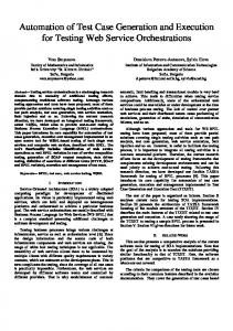
"test period" for data recording and efficiency calculation
5
5 min
I/////////H h"
steady-state period (20 min or 4 T )
H
Fig. 1 Steady-state period and test period given by ANSI/ASH RAE 1986 Standard
93-
inlet fluid temperature and mass flow rate prior to and during the period when the data are taken. It is required by ANSI/ASHRAE 93-1986 Standard that: (1) the test should be performed during periods when the sky is clear such that the solar irradiance incident upon the collector aperture plane does not vary more than ±32 W/m for durations of ten minutes or 2 time constants, whichever is greater, both prior to and during the period when the data are taken; (2) the fluid inlet temperature Tt and the flow rate should remain constant within ±2 percent (or ±1.0°C) and .000315 1/s whichever is greater, respectively, for 15 min prior to each period in which data will be taken to calculate the efficiency values; and (3) the ambient temperature shall vary by no more than ± 1.5°C during the same interval. The efficiency values are determined by integrating the data over a time period equal to the time constant or five min, whichever is larger. That is, the test should remain at a steady or quasi-steady condition for a continuous 20 min or 4 time constants, whichever is larger (Fig. 1). Though the above testing conditions would result in small scatter uncertainty, it could become time-consuming when performed in areas with variable weather condition, for example in Taiwan. It will be examined in the present study to see whether it is possible to shorten the required steadystate period. The efficiency calculation is based on the data recorded in the test period as shown in Fig. 1. This revision given in ANSI/ ASHRAE 93-1986 Standard can reduce the error due to the effect of collector transient response induced before the steadystate period, which was also found by many researchers (e.g.,Exell et al., 1988; Edwards and Rhee, 1981; Proctor, 1984). Edwards and Rhee (1981) first noted the effect of collector dynamics on steady-state testing results and derived a correction method based on a first-order or one-node dynamic model of the collector. Proctor (1984) has also noted this problem
and defined the "steady state" as the condition when the variation of the mean fluid temperature inside the collector is less than 0.75 °C over the testing period. Furthermore, the minimum length of the testing period shall be three residence times of fluid in the collector or two residence times plus five min if the residence time is longer than five min. The data at the middle residence time or the five-min segment of the testing period is to be recorded and used for the efficiency evaluation. The purpose of taking an additional two residence times or the five-min segment is to ensure that the dynamic effect before the testing period will not pass to the recorded data. The use of residence time, however, is questionable. From the point of view of system dynamics, the collector transient response is well related to the time constant, instead of the residence time which is usually smaller than the time constant (Prapas et al. 1988). Furthermore, the "settling time" is more precise and appropriate for estimating the time period in which the transient effect is present and thus was used in the present study as the time criterion for selection of the steady-state period. The time constant defined by ANSI/ASHRAE 93-1986 Standard is based on a first-order or one-node model of collectors which has been proved to be unable to accurately predict the dynamic responses (Smith, 1986). Hence, a modification using the second-order time constant based on a two-node model was made and from which the settling time was used as the time base in the selection of steady-state period for the test. The steadiness of the testing conditions as well as some other requirements given by ANSI/ASHRAE 93-1986 Standard were also modified in the present study such that the test can be easily performed in areas with variable weather conditions. In the meantime, to make the best use of the available time suitable for steady-state testing, an expert testing system was also developed.
II Automation of Collector Testing To shorten the duration of steady-state collector testing, a PC-based intelligent automatic testing system or expert system was developed in the present study. The hardware of the expert system consists of: (1) a test stand; (2) a constant level and constant temperature bath for supplying a steady flow to the collector; (3) a flow control valve for flow rate regulation; (4) a PC-based numerical controller for temperature and flow rate
Nomenclature Ac = collector aperture area, nr Cp = heat capacity of fluid, kJ/kgK pR(Ta)„ = thermal performance parameter of collector at solar noon, dimensionless FRUL = thermal performance parameter of collector, W/ m2oC IT = irradiation on the collector slope, W/m2 IT = average irradiation on the collector slope, W/m2 m = mass flow rate through collector, kg/s m = average mass flow rate through collector, kg/s Q = heater power in the bath, kW 258 / Vol. 112, NOVEMBER 1990
qu = rate of energy delivered by collector,W s = sample standard deviations Ta = ambient temperature, °C Tbath = fluid temperature in the constant-level bath, °C Te = fluid temperature at the exit of the collector, °C Tt = fluid temperature at the inlet of the collector, °C T'i.max = maximum fluid temperature at the inlet of the collector given by the manufacturer, °C V = volumetric flow rate, cc/ min j)„ = solar-noon efficiency T = first-order time constant, sec
time delay in the secondorder model, sec effective second-order time constant, sec T = 95 percent settling time, sec f = damping ratio of the collector, dimensionless At = time period of steady-state data recording, sec temperature rise across the AT,, collector (= Te — Tt), °C AT. = average temperature rise across the collector (= Te - T,), °C ATia T, - Ta, °C Td
95
AT,„ = T, - T„ °C Transactions of the AS ME
Downloaded 05 Nov 2008 to 140.112.113.225. Redistribution subject to ASCE license or copyright; see http://www.asme.org/terms/Terms_Use.cfm
adjustment; (5) a cover-up actuated by an air hydraulic cylinder through the PC for the shading of sunshine during the time constant test; (6) a data acquisition system for the measurement of irradiation, temperatures, flow rate, wind speed, etc.; and (7) an electronic timer to automatically turn the whole test system on in the morning and off at night. (See Fig. 2 for the testing system configuration and Fig. 3 for the schematic of operation.) The whole test system can be divided into two categories according to its function: the automatic measurement and the automatic control systems. An IBM-PC was used for data acquisition, decision making on the steadiness of testing conditions and the data recording action, computation in the temperature and flow rate control, data analysis and results plotting, sequential control of the whole testing procedures, etc. 1 Automatic Measurement System Design. The automatic measurement system consists of a YOKOGAWA 3880 hybrid recorder, an IEEE488 GPIB interface, and several sensors and their signal conversion circuits. A PSP pyranometer was used to measure the incident radiation upon the collector slope IT with ±2.5 percent uncertainty (including span error due to temperature dependence,linearity error, and cosine response error, all given by the manufacturer). A three-cup windmeter was used to measure instantaneous wind speed. T-type thermocouples were used to measure the temperatures at the collector inlet, the ambient, and the bath. To reduce the uncertainty in the measurement of temperature differences across the collector inlet and outlet, ATej ( = Te - T{), and across the ambient air and the collector inlet, i.e., Tt - Ta, two thermopiles made of five pairs of T-type thermocouples were used. The thermopiles were calibrated against a HP 2804 high
precision quartz thermometer to give an uncertainty < ±0.07°C (Huang, 1988). A turbine-type flowmeter MK508 with analog signal output was used to measure the mass flow rate through the collector and was calibrated with an uncertainty of < ± 2 percent. The automatic measurement is actually a data acquisition process which was controlled by a subroutine written in C language. The maximum uncertainty obtained in the present study in determining the collector efficiency r] is around 6.3 percent (including both measurement and scatter uncertainties) in which the scatter uncertainty due to random fluctuation of the process contributes a greater part. (See the Appendix.) 2 Automatic Control System Design. The hardware of the automatic control system essentially consists of a control valve for flow rate regulation; an electrical heater with SCR circuit to regulate the temperature in the constant level bath; a solenoidal valve to flush tap water into the bath if cooling is required during temperature control; an air hydraulic actuator to move the cover-up during the test of time constant; and an AD/DA interface to send control signals to control valve, SCR, and air actuator of the cover-up. (/) Control of Temperature in Constant-Level Bath. To maintain a constant water temperature at the collector inlet and avoid flow fluctuations due to blockage of water vapor bubbles, the electrical heater was installed inside the bath. So, there is a large transportation time delay in temperature wave front from the bath to the inlet of the collector (about 6 m apart). Since the desired temperature to be controlled is at the collector inlet and the temperature set point is inside the bath, an empirical relation, which was derived and determined experimentally, was used to set the bath temperature T bath for a desired inlet temperature 7): Thath —
PUMP
Fig. 2
Ti-(C/V)Ta 1-C/V '
(1)
where V is the volumetric flow rate in cc/min and C is a constant determined experimentally to be 135.2 min°C/cc. The water temperature in the bath was controlled digitally. The control signal generated from a control algorithm was first converted into a standard 0 - 10 V output through an 8-bit D/A interface. The analog signal was then used to trigger the SCR so that the heating rate of the electric heater inside the bath can be adjusted within the range 0 — 7 kW. PI, P, and ON/OFF control algorithms were used interchangably in the temperature control of the bath.The controller switches into PI algorithm when the bath temperature reaches ±2°C of the setting value. P-control algorithm was used when cooling is required. ON/OFF control associated with the maximum heating rate was used during the switching phase in order to accelerate the response. It takes about 15 min for each inlet temperature regulation and Tt can be controlled to within ± 1 °C (Fig. 4).
I
Configuration of testing system
DATA RECORDING, ANALYSING & RESULTS PLOTTING
IBM PC
CONTROLLER
ADC
VALVES HEATERS ACTUATORS
TEST STAND & CONSTANTLEVEL BATH
IEEE 488 INSTRUMENT
SENSORS
Fig. 3 Schematic of testing system operation Journal of Solar Energy Engineering
NOVEMBER 1990, Vol. 112 / 259
Downloaded 05 Nov 2008 to 140.112.113.225. Redistribution subject to ASCE license or copyright; see http://www.asme.org/terms/Terms_Use.cfm
PI CONTROL OF BATH TEMPERATURE 1
T
1
~1
r
1
1
r
SETTING VALUE
*^r"f^V^^A^^^T V
COLLECTOR INLET TEMPERATURE
10
I ^ 0
. w r - W 40
80
^^A^iywuJ 120
160
Vwww^-J 200
23T-+A' I (t)A
T95. Therefore, a correction with respect to the ramp response can also be made if necessary (Huang and Lu, 1982), though it is usually not required. VI Some Other Modifications At this stage, we have modified ANSI/ASHRAE 93-1986 Standard mainly in the selection of test period based upon the collector settling time and the statistical definition of steadiness condition. The following modifications were also made in the present study. (1) Number of Test Points. ANSI/ASHRAE 93-1986 Standard requires to take at least 16 data points in each solarnoon efficiency test. Among these points, at least four data points shall be taken for each value of T,-; two of the four data points shall be taken during the time period preceding solar noon and the other two shall be taken in the period following solar noon. The specific period being chosen so that the data points represent times symmetrical to solar noon. This requirement is made so that any low frequency transient effects (with response time in the order of several hours) that may be present will not bias the test results. This low frequency transient effect is mainly due to the long time response of the insulating or constructing material of the collector. In tropical areas, e.g., Taiwan, there is no collector freezing problem and the collector is usually operated at lower 7) Ta so that the insulation of the collector can be designed with relatively light weight material as compared to that required in high latitude areas. The low frequency transient response thus can be ignored. In this case, the test points can be chosen based upon the inlet fluid temperature alone. The scatter uncertainty for tests at each 7) is then less important than the variation of Tt. Hence, for simplification, at least eight test points is recommended to be taken according to the evenly distributed inlet fluid temperatures described as follows.
modification requires to take the eight steady-state test points evenly distributed for the inlet temperature ranging from ambient temperature 7„ to 7,-,max(3) Range of Ambient Temperature. ANSI/ASHRAE 931986 requires that the range of ambient temperatures for all reported test points comprising the efficiency curve shall be less than 30°C. If this requirement is obeyed for the tests in tropical areas, then the time available for the test in a year will be greatly reduced. However, it can be seen from the principles of the collector heat transfer that this requirement is not important as compared to the others such as steadiness and selection for test period, etc. Thus, the range of ambient temperature is not given in the present modification. (4) Wind Speed Range. ANSI/ASHRAE 93-1986 requires that the average wind speed shall be between 2.2 and 4.5 m/s during the test period and a minimum of 20 min or four first-order time constants, whichever is greater, for glazed collector under test just prior to the beginning of the test period. For the cases in which the natural wind conditions do not satisfy the above requirements, the natural wind may be supplemented with artificial wind. In many tropical areas such as Taiwan, the natural wind varies year around over a wide range. For the test results to be met with the situation of practical applications, it is recommended in the present study that the wind speed range still follow the requirement of ASHRAE 93-77 Standard. That is, the allowable average wind speed in the test is between 0 and 4.5 m/s. We summarize the modifications of ANSI/ASHRAE 931986 Standard in Table 2. The test results presented in Fig. 6 and 12 are based on the test method with this modifications.
VII Discussion and Conclusions The steady-state performance test of solar collectors using ANSI/ASHRAE 93-1986 Standard was revised and an auto(2) Distribution of Inlet Temperatures. ANSI/ASHRAE mation for collector testing was carried out in the present study 93-1986 Standard requires to take steady-state test points at in order that the test can be easily performed in areas with four different inlet fluid temperatures according to the distri- variable weather conditions. It was found that the time conbution obtained by setting 7, - T„ to 0, 30, 60, and 90 percent stant derived from the first-order dynamic model is unable to of the value of 7, - Ta at the manufacturer's recommended predict the transient response of the collector accurately. A maximum operating temperature of the collector. The present modification using the second-order time constants based on
Journal of Solar Energy Engineering
NOVEMBER 1990, Vol. 112/265
Downloaded 05 Nov 2008 to 140.112.113.225. Redistribution subject to ASCE license or copyright; see http://www.asme.org/terms/Terms_Use.cfm
Table 2 Summary of the present modification on ANSI/ASHRAE 931986 Standard ANSI/ASHRAE 93-1986
Present Modifications
Time constant
first-order r
second-order re or 795
Test period definition
20 minutes or 4 r
10 minutes or r95 + 5 minutes
Steadiness definition
absolute
statistical
Steadiness for IT
< ± 3 2 W/rr?
s,T < 0.0257 r
Steadiness for T;
±1°C
not changed
Steadiness for m
< ±0.02m
s m < 0.01m
Steadiness for ATia
not given
* A I \ . < 0.5°C
Number of test points
at least 16
at least 8
No. of test points at each 2;
at least 4
at least 1
Time-symmetry test
required
not required
Average wind speed range
2.2 ~ 4.5 m/s
0 ~ 4.5 m/s
T{ distribution
by 0,30,60,90% of
evenly-distributed between
{Ti,mal-Ta)
r „ and Ti,ma*
u = 2 percent; ,= Vo.01 2 + 0.022 = 2.24 percent
w,TiS = 2.5 percent; w/r,„ = 2.5 percent; w / r = \/o.025 2 + 0.0252 = 3.54 percent. For ATei, the maximum scattering was .found to be around 0.2°C and the maximum scatter uncertainty is thus wATehs = 0.2/4.5 = 0.044 for a minimum ATei = 4.5°C observed in the tests. The maximum measurement uncertainty is wATehll = 0.07/4.5 = 0.016. Therefore, from equation (A2), wAr = V0;0442 + 0.0162 = 4.7 percent. Hence, the maximum combined uncertainty w, in the present experiments can be estimated by equation (Al),
= Vo.02242 + 0.03542 + 0.0472 = 6.3 percent. By following the statistical definition of the steadiness and assuming that all the measurement uncertainties are at 20:1 odds, this uncertainty can be considered to be at 20:1 odds (or 95 percent confidence).
.Readers of... lar Energy Engii Solar Engineering — 1990 Editors: J. Taylor Beard, M.A. Ebadian This publication includes selected technical innovations, as well as indications of the political status of solar energy in a national policy. Selected research reports have come from such areas as solar energy fundamentals, analysis of heat transfer, and thermodynamic systems for energy conversion. 1990 Order No. H00581 $90 List / $63 ASME Members
ISBN No. 0-7918-0472-0
436 pp.
To order, write ASME Order Department, 22 Law Drive, Box 2300, Fairfield, NJ 07007-2300 or call 1-800-THE-ASME (843-2763) or FAX 1-201-882-1717.
Journal of Solar Energy Engineering
NOVEMBER 1990, Vol. 112 / 267
Downloaded 05 Nov 2008 to 140.112.113.225. Redistribution subject to ASCE license or copyright; see http://www.asme.org/terms/Terms_Use.cfm