WSEAS TRANSACTIONS on COMMUNICATIONS
Jyh-Horng Wen, Chuan-Wang Chang, Sheng-Fong Lin
An Effective Cancellation Technique of Cochannel Interference Based on Multiuser Detection Scheme for MFSK/FH-SSMA Systems JYH-HORNG WEN1, CHUAN-WANG CHANG2,3,* and SHENG-FONG LIN2 1 Department of Electrical Engineering, Tunghai University 2 Department of Electrical Engineering, National Chung Cheng University 3 Department of Electrical Engineering, Chien Kuo Technology University No. 1, Chieh Shou N. Rd., Changhua City, Taiwan, R.O.C. TEL:+886-4-7111111 Ext.3234 Email:
[email protected] *Correspondence address
Abstract: - The performance of a multilevel frequency shift keying/frequency hopping-spread spectrum multiple access (MFSK/FH-SSMA) system over a cochannel interference scenario is dependent on multiuser detection schemes. Many investigations have demonstrated huge potential capacity and performance improvement by using multiuser detection schemes. However, their schemes are extremely complex while the total number of users is increased because the multiuser interference becomes larger. In this paper, we propose a novel multiuser detection scheme to reduce the complexity of decoding process. The performance of the system with the proposed scheme over a nonfading channel is simulated and compared with that of conventional and other multiuser interference cancellers. Simulation results show that the proposed scheme reduces the system complexity and improves the bit error rate (BER). Key-Words: - Multilevel Frequency Shift Keying (MFSK), Frequency Hopping-Spread Spectrum Multiple Access (FH-SSMA)
Frequency diversity is achieved by applying an FH
1. Introduction in
pattern onto a data pattern and is obtained to
communication systems, such as DS-SSMA [1]-[3]
mitigate multipath and diversity of the interferences
and FH-SSMA[4],[5], permit many simultaneous
as seen by any given user [6], [7]. However, the user
users to share a single transmission medium through
capacity in FH-SSMA systems is hampered by
the assignment of unique codeword or hopping
multiuser cochannel interference (CCI). The term
pattern to each user, respectively. Nevertheless,
“CCI”, or named “hit”, occurs when more than one
unlike in DS-SSMA where the data bandwidth is
users’ tones occupy a specific frequency slot at the
spread by direct modulation with a wideband
same time. An MFSK/FH-SSMA system was
spreading code, the spreading code in FH-SSMA is
proposed by Goodman [7] to reduce the effect of
used to control the sequence of carrier frequencies.
hits.
The
spread
ISSN: 1109-2742
spectrum
techniques
248
In
addition,
by
properly
designing
Issue 4, Volume 9, April 2010
WSEAS TRANSACTIONS on COMMUNICATIONS
Jyh-Horng Wen, Chuan-Wang Chang, Sheng-Fong Lin
frequency-hopping patterns, CCI can also be
2. System Description
minimized as few as possible. Various kinds of
In an MFSK/FH-SSMA system, there are M
address code sets have been studied [8].
pairs of transmitters and receivers. Fig. 1 shows the
For MFSK/FH-SSMA systems, Mabuchi et al.
block diagram of one transmitter. In the transmitter,
proposed a multiuser detection scheme based on
every k bits of the input binary data are stored in a
canceling CCI [9]-[14]. In the scheme, the receiver
k-bit buffer. The k-bit message is then mapped into a
decodes all users’ candidate data symbols jointly
symbol selected from one integer of the set
and then these symbols are utilized to produce the
{0,
estimates of the received data matrix. By using the
user, where K=2k . The symbol xm with symbol
maximum likelihood decision rule, the matrix that
duration of Ts is subdivided into L chips and then
has the most number of coincident entries with the
the vector Xm = ( Xm,0, Xm,1,…, Xm,L-1 ) is produced,
received data matrix is selected. A modified
where Xm,i = xm for i = 0, 1,…, L-1. Fig. 2 shows an
Mabuchi scheme was proposed by Lin et al. [15],
instance of the encoding procedure, where the data
which further improved the system performance.
vector X1 = (3, 3, 3, 3, 3) is showed in the matrix
However, these two schemes are unacceptable in
representation for K = 8 (k = 3) and L = 5. Each
many applications because of their huge amount of
element of the resulting vector Xm is then translated
computational complexity especially when the total
in frequency by an amount that is determined by the
number of users increases in the system. Therefore,
corresponding element of hopping sequence Rm,
another scheme based on modification of Mabuchi’s
where Rm is generated by different address element
scheme was proposed by us to improve the system
γm(m=1,2,…, M) selected from GF(K). The symbol
complexity [16]-[19]. Furthermore, an effective
GF(K) denotes the finite field (Galois field) of K
interference cancellation algorithm that we proposed
elements. Let the address (hopping) pattern of user
will get outstanding performance especially in
m be denoted by a vector
nonfading environments.
1, 2," , K − 1} and denoted by xm for the mth
R m = ( Rm,0 , Rm,1 , " , Rm, L −1 )
The rest of this paper is organized as follows.
(1)
In Section 2, a novel multiuser detection scheme
where Rm,i ∈ GF(K) represents the frequency
used in MFSK/FH-SSMA systems is proposed to
channel occupied by the address at time slot i. With
cope with the increasing complexity resulting from
the addition operator denoted by “♁”, we will
the augmentative number of active users. The
derive the encoded data pattern Ym by imposing the
algorithm here gives a new method in choosing the
hopping pattern Rm upon the data pattern Xm. That is,
candidate rows that will dramatically reduce the
the vector Ym = (Ym,0, Ym,1, … , Ym,L-1) transmitted by
complexity of the system. In Section 3, the
user m can be derived from Ym=Xm+Rm, where Ym,l,
numerical analysis of the complexity of this system
Xm,l, and Rm,l ∈ {0, 1, 2, …, K-1}. The addition rule
is carried out. In Section 4, computer simulations for
denoted by “♁” here is exclusive-OR (XOR)
various kind of schemes in the MFSK/FH-SSMA
addition (the addition is operated after Rm and Xm
system will be carried out and the results of them
are transformed into binary digits). As a result, the
will also be discussed. Finally, in Section 5, the
center frequencies of the data pattern elements are
main results of this paper are summarized.
changed (hopped) by the elements of the hopping pattern. The matrix representation of Y1 in Fig. 2
ISSN: 1109-2742
249
Issue 4, Volume 9, April 2010
WSEAS TRANSACTIONS on COMMUNICATIONS
Jyh-Horng Wen, Chuan-Wang Chang, Sheng-Fong Lin
shows an example of the output of the frequency
Proposition 2: In the decoded matrix, any two
synthesizer derived from the hopping pattern R1 =
frequency tones selected arbitrarily
(4, 3, 6, 7, 5) and the data symbol pattern X1 = (3, 3,
from L tones of the same undesired
3, 3, 3).
user are different. The proof of this proposition will be presented in
Without loss of generality, it is assumed that
Appendix.
user 1 is the desired user and the others are the undesired ones to CCI. Moreover, it is assumed that
There is an important concept concealed in
the FH patterns of all users are known and are
proposition 2, where it exhibits each tone in an
distinct to each other.
incorrect row must comes from different users in the decoded matrix. That is, all the undesired users will at most contributes one of its tones to a specific
2.1. Address Code Assignment
incorrect row. The concept showed above will
In this section, we briefly review the method of
provide an important idea of “PO row”.
hopping pattern assignment and invoke some propositions
to
show
the
properties
of
the
transmission patterns. In order to make the detection
2.2. A Novel Multiuser Detection Algorithm Based on Mabuchi’s Scheme for MFSK/FH-SSMA System
precisely, the address pattern sets having good cross-correlation properties must be found. From the results presented in [8], it has been shown that the
In this section, a novel decoding algorithm for
code set constructed by Einarsson is the optimal one
multiuser detection scheme is proposed to improve
for the MFSK/FH-SSMA system [6].
the complexity of the MFSK/FH-SSMA system. Fig.
Let the address pattern of user m be denoted by
3 shows the receiver structure of the proposed
the vector Rm. Einarsson [6] proposes the following
scheme. As we know, two previous works on
equation to generate a set of K addresses.
multiuser detection schemes proposed by [9] and
R m = (γ m , γ m β , γ m β 2 , " , γ m β L −1 ) ,
[14] will generate great amounts of candidate
(2)
matrices as the number of the active users increases.
where γm is an element of GF(K) assignment to user
For the reason, the algorithm we proposed will
m and β is a fixed primitive element of GF(K). To
focus on the reduction of the number of candidate
see what transmitted signals Ym(m=1,2,…,M) can
matrices. In our scheme, the majority rows would be
interfere with each other, properties of the pair of
selected as the candidate rows of the desired user,
transmitted sequences are enumerated as follows.
while on the other side, the row named “PO row”
Let Y1 and Y2 denote two sequences generated by
(Pseudo-Optimal row) would be respectively chosen
two different hopping sequences R1 and R2,
for the other users in their decoded matrices. The
respectively. It is noted that the properties showed
algorithm of the proposed multiuser detection
next are all based on the word synchronous system.
scheme
Proposition 1: With appropriate choice of β, two
summarized as follows:
transmitted vectors with different
the
MFSK/FH-SSMA system is
2.2.1. Firstly, the receiver detects the energy in each
address will coincide in at most one
time-frequency cell of the received matrix.
chip [6].
ISSN: 1109-2742
for
The energy in each cell is the summation of
250
Issue 4, Volume 9, April 2010
WSEAS TRANSACTIONS on COMMUNICATIONS
Jyh-Horng Wen, Chuan-Wang Chang, Sheng-Fong Lin
transmitted tones from all active users. Fig. 4
user, all the L tones of the user for decoding
shows an example where K = 8, L = 3 and M
will appears in the correct row in nonfading
= 5.
environments.
the number of interference user increases, it
symbols of each user in Fig. 4 (d). In the
is not necessarily that the correct row is
desired user’s (user 1) decoded matrix D1, are
considered
property
row” among the K rows. Nevertheless, when
5) and then choose the candidate of the data
rows
two
that has the most chances to become the “PO
symbols by the FH patterns Rm (m= 1, 2, …,
majority
the
described above, the correct row is the one
2.2.2. The receiver decodes every user’s data
the
From
always the “PO row”, the name “Pseudo” is
as
thus applied.
candidates of the correct data symbol in the desired user’s decoded matrix. While in the
2.2.5. Let Jm (1≤ Jm≤K) denote the number of the
other users’ decoded matrix, the “PO row” is
candidate rows decoded by the hopping
selected as candidates of the correct data
pattern Rm. Therefore, when in the receiver of
symbol. The reason for the choice of
user 1, J1 means the number of majority rows
majority row instead of “PO row” in the
and Jm (m≠1)
desired user’s decoded matrix is to enlarge
decoded matrix, respectively. Each candidate
the probability of selecting the correct row.
of the desired user’s data symbols is
Fig. 4 (d) shows the decoded matrices of
re-encoded and added with the candidate of
users derived from the hopping patterns Rm
the other users’ data symbols using the
(m= 1, 2, …, 5) and the received matrix in
“energy SUM“ operation. Since each time we
Fig. 4 (c).
select one candidate row from each user,
means the PO rows in the mth
M
∏ Jm candidate matrices
there are total
2.2.3. Definition of PO row: A row which satisfies
m=1
the following two conditions is named as the
generated from this procedure. The example
“PO row”, the first condition is that the row is
in Fig. 4 (d) shows that there are two
a complete row (majority row) and the
candidates for the data symbols of users 1
second is that this complete row must be the
and one candidate for the data symbols of the
row having the largest energy among the K
other three users. Therefore, there are total
rows. The name “PO row” is denominated by
two candidate matrices, “t2” and “t4”,
us and is of the full name “Pseudo Optimal
derived from the “sum” operation of each
row”. This is because in most of the situations,
re-encoded
the row belonging to the “PO row” is
matrix
generated
from
the
combination of candidate rows. Nevertheless,
generally the correct data row.
there are four candidate matrices in the
2.2.4. The reason for choosing the PO row: From
Mabuchi’s scheme.
proposition 2, one interference user will at M
2.2.6. Among these ∏ Jm candidate matrices, we
most contribute one tone out of its L tones to
m=1
a specific row. Moreover, owing to the
choose the one that has the most number of
matched dehopping pattern for the desired
ISSN: 1109-2742
coincident cells with the original received
251
Issue 4, Volume 9, April 2010
WSEAS TRANSACTIONS on COMMUNICATIONS
Jyh-Horng Wen, Chuan-Wang Chang, Sheng-Fong Lin
considered.
matrix. In other words, the energy of each cell in the candidate matrix is the same with
Since Jm (1≤ Jm≤K) denote the number of the
that in the original received matrix, and the
candidate rows (complete rows) decoded by the
number of the cells is the maximum. Finally,
hopping pattern Rm. In both of the multiuser
the correct data symbol of the desired user
M
detection schemes in [9] and [14], there are ∏ Jm
would be extracted. In Fig. 4 (e), the fourth
m=1
candidate matrix named “t4”, which consists
(1≤ Jm≤K) candidate matrices of received matrix in
of data symbols (7, 5, 3, 2, 2) extracted from
each scheme. The symbol Ncandi is defined as the
each decoded matrix, is the one that has the
number of the candidate matrices normalized by the
most number of coincident cells with cells of
number of symbols per user [9] and is used to
the
measure the system complexity.
received
matrix
in
Fig.
4
(c).
Consequently, we can decode the correct data N candi =
symbol “7” of the desired user (user 1) from
Number of total candidate matrices Number of total symbols per user
.
(2)
the selected candidate matrix “t4”. On the contrary, there are four candidate matrices
In the following, theoretical analysis will be
generated in the Mabuchi’s scheme and
established. Firstly, the independence between all
random choice between the matrices “t2” and
the decoded matrices is assumed. A tight bound
“t4” would be applied. Finally, a decoding
proposed by [6] derives the probability that an
error in the Mabuchi’s scheme happens.
incorrect row to be evolved into a complete row. Thus, in each of the decoded matrix, the probability
In this example, we have shown that the
for an incorrect row to become a complete row is
proposed scheme can decode the correct data symbol even when the errors will occur in the
Pcmp =
Mabuchi’s scheme.
1 M −1− i ⎤ ⎡ ) Π ⎢ 1 − (1 − ⎥. i= 0 K −i ⎣ ⎦ L −1
(3)
Over the K-1 incorrect rows, the probability that exactly q unwanted rows belong to the complete
3. Performance Analysis of System Complexity
rows is ⎛ K − 1⎞ P( q) = ⎜ ⎟ ⎡⎣ Pcmp ⎤⎦ ⎝ q ⎠
3.1. The Number of Candidate Matrices in Mabuchi’s Scheme
⎡⎣1 − Pcmp ⎤⎦
K −1− q
.
(4)
The mean value concerning the average number of
In this subsection, the number of candidate
incorrect complete rows in a decoded matrix is
matrices generated in the decoding process of
defined and expressed as
Mabuchi’s and Lin’s scheme is analyzed (it is the
__ K −1 ⎧⎛ K −1⎞ q K −1−q ⎫ J m = Σ q ⋅ ⎨⎜ ⎬. ⎟ ⎡⎣ Pcmp ⎤⎦ ⎡⎣1 − Pcmp ⎤⎦ q= 0 q ⎠ ⎩⎝ ⎭
same in both schemes). The analysis here assumes time and frequency synchronization of the FH pattern generator in the transmitter and receiver.
(5)
Finally, through the multiplication of all the number
Hop synchronous is also assumed. The situation
of candidate matrices in each decoded matrices, the
where there is no noise or fading in the system is
ISSN: 1109-2742
q
averaged number of candidate matrix is derived as
252
Issue 4, Volume 9, April 2010
WSEAS TRANSACTIONS on COMMUNICATIONS
Jyh-Horng Wen, Chuan-Wang Chang, Sheng-Fong Lin
scheme and the Lin’s scheme in a non-fading
M
____ __ ⎞ ⎛ N candi = ⎜ 1 + J m ⎟ . ⎜ ⎟ ⎝ ⎠
channel. For instance, given nine users, Pb(M) =
(6)
3.11×10-6
= 4.06×10⁻² for the conventional receiver,
It is noted that the number “1” in equation (6)
Pb(M) =
-3
5.7×10 for the Mabuchi’s canceller, and Pb(M) =
represents the correct complete row which occurs
2.8×10⁻⁵ for the Lin’s canceller. Noted that, as the
inevitably in interference only channel.
number of active users M increases, the bit error rates (BER) of the Mabuchi’s scheme, the Lin’s
3.2. Reduction Efficiency of System Complexity
scheme and the proposed scheme approach the bit error rate of the conventional scheme. This is
In this subsection, a parameter η is defined to
because there are too many ambiguous candidates in
measure the degree of complexity reduction. The
the decoded matrix, which dramatically decreases
reduction efficiency of the system complexity is
the probability of correct decisions in all schemes.
defined as
η=
for the proposed canceller, while Pb(M)
Fig. 5 reveals that when the BER is fixed at 10-3,
( N ) Mabuchi − ( N ) Proposed ( N ) Mabuchi
there are 6 users supported by the conventional ,
scheme, 8 users in the Mabuchi’s scheme and 12
(7)
users in both the Lin’s and the proposed schemes. The result shows that high traffic load is admitted in
where N is the average candidates (candidate rows
the proposed scheme under a fixed value of BER.
or matrices per symbol, per user) in the process of decoding.
4.2. Analysis of System Complexity In this subsection, the system complexity of the system using the proposed CCI canceller is
4. Numerical and Simulation Results
compared with the Mabuchi’s CCI canceller. The
In this section, the presented numerical results
analysis in this subsection is concentrated on the
are evaluated for various values of system
number of candidate rows and matrices. Moreover,
parameters K, M and L. To better illustrate, the
in the conventional scheme, none of the candidate
results will be presented into two parts: “analysis of
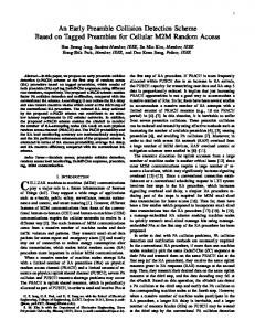
matrices will be generated. Fig. 6 shows the number
bit error rate” and “analysis of system complexity”.
of candidate matrices Ncandi versus the number of active users M in log scales for the two schemes: the
4.1. Analysis of Bit Error Rate
Mabuchi’s canceller in [9], and the proposed
In this section, the performance of the system
receiver. The number of the candidate matrices was
using the proposed CCI canceller is compared with
with K=16 and the hopping pattern length L=5. As
those systems using the conventional, the Mabuchi’s
expected, the value Ncandi in the Mabuchi’s receiver
and the Lin’s CCI canceller. Fig. 5 shows the bit
increases nonlinearly as M increases. On the
error probability versus the number of active users
contrary, the value Ncandi increases almost linearly in
for the four schemes K=16 and L=5 without fading.
the proposed receiver as M increases. Besides, the
As expected, the proposed scheme performs better
numerical and simulated results of Ncandi in the
than the conventional scheme, the Mabuchi’s
ISSN: 1109-2742
Mabuchi’s scheme will also be compared. From this
253
Issue 4, Volume 9, April 2010
WSEAS TRANSACTIONS on COMMUNICATIONS
Jyh-Horng Wen, Chuan-Wang Chang, Sheng-Fong Lin
figure, it is shown that these two curves are most of
generality, we assume that user 1 is the desired user.
the time coincidence in values. Table. 1 shows the
For the mth user(m≠1), we have Ym=Rm+Xm·1. After
detail values of the number of candidate matrices for
decoding by the hopping pattern of the desired user,
the Mabuchi’s scheme and the proposed scheme,
the frequency position at the ith chip of the mth user
and the reduction efficiency of these two schemes is
is
also calculated. As shown in Table 1, when the
Ym ,i − R1,i = (γ m − γ 1 ) β i −1 + xm .
number of active users M is greater than 11, the
(8)
reduction efficiency η will attain more than the percentage of ninety. Moreover, the reduction
Now consider the next symbol Ym,j-R1,j at chip
efficiency increases as the number of active users
position j, where j≠ i. We have
increases.
Ym, j − R1, j = (γ m − γ 1 ) β j −1 + xm .
Finally, Fig. 7 shows the complexity reduction
(9)
efficiency η versus the number active users M for the candidate matrices and candidate rows in a
If we assume equation (8) is equal to equation (9),
non-fading channel. From the results in this figure,
then we will derive
it can be observed that in spite of the reduction
β i −1 = β j −1 .
efficiency of candidate rows is not large, the
(10)
efficiency is almost reaches to the percentage of 100 as the number of active users M approaching to K.
The result derived in equation (10) conflicts with the finite field rule described in [20], where the conditions to the orders i, j of
β
meets i, j ≤ L
and L ≤ K-1. That is, any two frequency tones
5. Conclusions
selected from L tones of the same undesired user are
This paper developed a novel algorithm for the
different in the decoded matrix.
multiuser detection schemes to decrease system complexity in MFSK/FH-SSMA systems. The performance of the system has been analyzed and
Acknowledgment. This work was supported by the
compared with those of conventional the Mabuchi’s
National Science Council (Taiwan) under grant NSC
and the Lin’s CCI canceller. Simulation results show
98-2218-E-029 -004 -.
that the proposed scheme has much lower system complexity than the two multiuser detection
References:
schemes proposed by Mabuchi and Lin. Moreover,
[1]
C. Pateros, “Novel direct sequence spread spectrum
the bit error probability of the proposed scheme also
multiple access technique,” IEEE 21st Century Military
outperforms
Communications Conference Proceedings, vol. 1, pp.
the
other
detection
schemes
in
nonfading channels.
564-568, Oct. 2000. [2]
Y.K. Jeong, J.H.Cho, and J.S. Lehnert, “An asymptotic analysis of band-limited DS/SSMA systems,” IEEE
Appendix:
International Symposium on Information Theory, pp. 434,
In this section, the proof of the proposition 2 in
July. 2004.
section 2 will be presented. Without loss of
ISSN: 1109-2742
[3]
254
Yeon Kyoon Jeong, Joon Ho Cho, and J.S. Lehnert,
Issue 4, Volume 9, April 2010
WSEAS TRANSACTIONS on COMMUNICATIONS
[4]
[5]
Jyh-Horng Wen, Chuan-Wang Chang, Sheng-Fong Lin
“Performance bounds on chip-matched-filter receivers for
of interference for direct-sequence spread-spectrum
bandlimited DS/SSMA communications,” IEEE Trans.
multiple-access system,” IEEE J. Select. Areas Commun. ,
Commun., vol. 53. , no. 1, pp.131 –141, Jan. 2005.
vol. SAC-8, pp. 675-682, May 1990.
J.F.
Weng,
G.Q.
Xue,
Tho
Le-Ngoc,
and
S.
[13] R. Kohno, H. Imai, and M. Hatori, and S. Pasupathy, “An
Tahar, ”Analysis of multilevel-quantized soft-limiting
adaptive
detector for an FH-SSMA system,” IEEE International
spread-spectrum multiple-access communication networks
Conference on Communications, vol. 3, pp. 1380-1384,
in a power line,” IEEE J. Select. Areas Commun. , vol.
Jun. 2000.
SAC-8, pp. 691-699, May 1990.
Daeyoung Park, G.L. Byeong, “Iterative decoding in convolutionally systems,”
and
IEEE
turbo
coded
International
[7]
[8]
G.
Einarsson,
“Address
cochannel
interference
for
MFSK/FH-SSMA
algorithm for M-ary frequency shift keying signals,” IEEE
Conference
21st
on
assignment
Century
Military
Communications
Conference
Proceedings, vol. 2, pp. 1123-1128, oct. 2004.
for
a
[15] S.-Y. Lin, G.-C. Yang, S.-C. Tseng, and C.F. Hong,
time-frequency-coded, spread-spectrum system,” Bell Syst.
“Improved
Tech. J., vol. 59, no. 7, pp. 1241-1255, Sep. 1980.
MFSK/SSMA systems,” IEEE J. Select. Areas Commun.,
D.J.
Goodman,
P.S.
Henry,
and
V.
K.
Prabhu,
cochannel
interference
cancellation
for
vol. 17, no. 11, pp. 1940-1952, Nov. 1999.
“Frequency-hopping multilevel FSK for mobile radio,”
[16] H. Zhang, H. Yang, R. Luo, H. Wang, “Improved
Bell Syst. Tech. J., vol. 59, no. 7, pp. 1257-1275, Sep.
multiuser detector for fast FH/MFSK systems with
1980.
soft-limiter,”IEEE 2005 Int. Symposium on Microwave,
B.G. Haskell, “Computer simulation results on frequency
Antenna, Propagation and EMC Technologies for Wireless
hopped MFSK mobile radio-noiseless case,” IEEE Trans.
Commun., Vol 2, pp. 1464 – 1467, Aug. 2005.
Commun., vol. com-29, no. 2, pp.125 –132, Feb. 1981. [9]
of
[14] Y. Zaihe, Y.Q. Shi, and S. Wei, “A practical classification
Communications, vol. 9, pp. 2784-2788, Jun. 2001. [6]
canceller
[17] Z. Yu, C.C. Chai, T.T. Tjhung, “Multiuser detection
T. Mabuchi, R. Kohno and H. Imai, “Multiuser detection
algorithm based on iterative interference cancellation for
scheme based on canceling cochannel interference for
MC-MFSK systems,” Personal, Indoor and Moible Radio
MFSK/FH-SSMA system,”
IEEE
J.
Select.
Areas
Communications, IEEE 2004 PIMRC, vol. 4, pp. 2915 –
Commun., vol. 12, no. 4, pp. 593-604, May 1994.
2919, Sep. 2004.
[10] R. Kohno, H. Imai, and M. Hatori, “Cancellation
[18] Z. Yu, T.T. Tjhung, C.C. Chai, “Performance of
technique of cochannel interference in asynchronous
MC-MFSK systems with IIC-based multiuser detection
spread spectrum multiple access system,” Trans. On The
over
Institute of Electronics, Information and Communication
Telecommunications Conference, vol. 2, pp. 893-897, Dec.
Engineerings Japan, vol. J65-A, no. 5, pp.416-423, May
2004.
1983.
Rayleigh
fading
channels,”
IEEE
Global
[19] S. Ahmed, L.L. Yang, L. Hanzo, “Successive Interference
[11] S. Verdu, “Optimum multiuser asymptotic efficiency,”
Cancellation in Clipped and Product Combining aided
IEEE Trans. Commun., vol. COM-34, pp. 890-897, Sept.
FFH Multi-User Systems,” IEEE Vehicular Technology
1986.
Conference, vol. 5, pp. 2188-2192, Spring 2006. [20] B. W. Stephen, Error Control System for Digital
[12] R. Kohno, H. Imai, and M. Hatori, and S. Pasupathy,
Communication and Storage, NJ: Prentice Hall, 1995.
“Combination of an adaptive array antenna and a canceller
ISSN: 1109-2742
255
Issue 4, Volume 9, April 2010
WSEAS TRANSACTIONS on COMMUNICATIONS
Binary Data Buffer k-bits
Jyh-Horng Wen, Chuan-Wang Chang, Sheng-Fong Lin
XOR Addition
Transform to K levels
X1
♁
Y1
Energy Detector
Frequency Synthesizer
Hopping B 1 Sequence R1
Delay
♁
Choose Majority rows
Address Pattern R1
Com parison
♁
Sum
Data Decision
Transform to Binary
Binary Data
Address Pattern R1 . . .
Fig. 1
♁
Block diagram of an MFSK/FH-SSMA
Address Pattern R1
transmitter ♁
Choose P.O. rows
Address Pattern R2
Address Pattern R2
Data Matrix X1 = (3,3, 3,3,3)
7 6 5 4 3 O O O O O 2 1 0 Tc
TS = LTc
FH Code Matrix
R1 = (4,3,6,7,5), γ 1 = 4
7 O 6 O 5 O 4 O 3 O 2 1 0
TS
♁
. . .
Encoded Data Matrix Y1 = (7, 0, 5, 4, 6)
♁
7 O 6 O 5 O 4 O 3 2 1 0 O
. . . ♁ Address Pattern RM
TS
Choose P.O. rows
Address Pattern R2
♁ Address Pattern RM . . .
♁ Address Pattern RM
Fig. 2 An example of the encoding procedure for an MFSK/FH-SSMA transmitter
Fig. 3
The receiver structure of the proposed scheme for the MFSK/FH-SSMA system
ISSN: 1109-2742
256
Issue 4, Volume 9, April 2010
WSEAS TRANSACTIONS on COMMUNICATIONS
Jyh-Horng Wen, Chuan-Wang Chang, Sheng-Fong Lin
1e+0 ○○ ○
1e-1
Bit error probability
1e-2
◇◇ ◇
1e-3 1e-4 K= 16, L= 5, interference-only
1e-5
conventional scheme (analytical) conventional (simulation) Mabuchi's scheme (analytical) Mabuchi's scheme (simulation) Lin's scheme (analytical) proposed scheme (simulation)
1e-6 1e-7 ○
1e-8 ○
4
○
6
8
10
12
14
16
Active users M
◇
Fig. 5
○
BER versus the number of active users M using
◇
the
○
conventional
canceller,
the
Mabuchi’s
◇ ○
canceller, the Lin’s canceller, and the proposed canceller in a non-fading channel ◇ ◇ ○ ○ ○ ○○
◇
○
◇ ◇ ○ ○
◇ ◇ ○ ○
◇ ◇
◇
○
○ ○ ○ ○ ◇
◇ ◇ ○
◇ ◇◇○ ○ ○
◇
○
○
○ ○◇
1e+5 Mabuchi's scheme (simulation) Mabuchi's scheme (analytical) Proposed scheme (simulation)
1e+4 ◇
○
○
○
○ ◇
◇ ○ ○ ○
○
◇
◇
○ ○
◇
K= 16, L= 5, interference only
◇
◇
Ncandi (log scale)
◇
◇
○ ◇ ○
◇ ○
1e+3
1e+2
1e+1
1e+0
Fig. 4 An example of decoding procedures proposed by
1e-1 4
us
6
8
10
12
14
16
Active users M
Fig. 6
The number of candidate matrix
Ncandi (per
symbol, per user) versus the number of active users M using the Mabuchi’s canceller and the proposed canceller in a non-fading channel
ISSN: 1109-2742
257
Issue 4, Volume 9, April 2010
WSEAS TRANSACTIONS on COMMUNICATIONS
Candidate matrices Candidate rows (not for the desired user)
100
Complexity reduction efficiency η
Jyh-Horng Wen, Chuan-Wang Chang, Sheng-Fong Lin
K= 16, L= 5, interference only 80
60
40
20
0 2
4
6
8
10
12
14
16
Active users M
Fig. 7
The complexity reduction efficiency η versus the number active users M in a non-fading channel, where the efficiency η is defined in equation (7)
Reduction Efficiency
Active users M
Mabuchi’s Scheme
Proposed Scheme
5
1
1
0
6
1.011
1.004
0.673
7
1.06
1.018
4.16
8
1.23
1.056
14.05
9
1.69
1.135
33.01
10
3.10
1.278
58.71
11
8.50
1.529
82.01
12
45.75
1.969
99.69
13
367.7
2.657
99.28
14
2604.5
3.86
99.85
15
20584.8
5.849
99.97
η
Table. 1 The number of the compared candidate matrices and the reduction efficiency (K = 16, L = 5,non-fading channel)
ISSN: 1109-2742
258
Issue 4, Volume 9, April 2010