An Effective NF-FF Transformation with Helicoidal Scan Tailored for Elongated Antennas: an Experimental Validation F. D’Agostino (1)
(1),
F. Ferrara (1), J.A. Fordham (2), C. Gennarelli (1), R. Guerriero M. Migliozzi (1), G. Riccio (1), C. Rizzo (3)
(1),
D.I.I.I.E. - University of Salerno, via Ponte Don Melillo, 84084 Fisciano (SA), Italy.
[email protected]
(2)
MI Technologies, 1125 Satellite Blvd, Suite 100 Suwanee, Georgia 30024-4629, USA.
[email protected]
(3)
MI Technologies Europe, 3 Hither Green Southbourne Emsworth, PO10 8JA, UK.
[email protected]
A b s t r a c t – This work concerns the experimental validation of a new near-field – far-field transformation technique with helicoidal scanning tailored for elongated antennas. Such a transformation is based on the theoretical results relevant to the nonredundant sampling representations of the electromagnetic fields and uses a proper source modelling particularly suitable to deal with this kind of antennas. By employing such an effective modelling, instead of the spherical one, it is possible to remarkably reduce the error related to the truncation of the scanning zone, since measurement cylinders with a diameter smaller than the source height can be used. The validity of this innovative scanning technique is assessed by comparing the reconstructions obtained from the data directly measured on the classical cylindrical grid with those recovered from nonredundant measurements on the helix.
I. INTRODUCTION The techniques for the reconstruction of antenna radiation patterns from near-field (NF) measurements have been widely investigated and used for applications ranging from cellular phone antennas to large phased arrays and complex multibeam communication satellite antennas [1]-[4]. They have been proved to be efficient and attractive alternatives to conventional far-field (FF) and compact range measurements. Moreover, NF measurements can be performed in a controlled environment, as an indoor shielded anechoic chamber, which allows one to overcome those drawbacks that, due to weather conditions (rain, snow, etc.), electromagnetic (EM) interference and other, cannot be eliminated in FF measurements. Each member of the antenna measurement techniques community can profit today by about fifty years of research activity on NF data acquisition and related NF–FF transformations. Over these years, many solutions have been proposed to meet the demands of the various applications. In this framework,
significant improvements in the performance of NF measurements have been recently achieved. They are based on the spatial bandlimitation properties of radiated EM fields [5], on their nonredundant sampling representations [6], and on the optimal sampling interpolation (OSI) expansions of central type [7]. In particular, a significant reduction of the number of required NF data (and, as a consequence, of the corresponding measurement time) has been obtained for all the conventional scannings [3]. Moreover, innovative scannings have been proposed to further reduce the time needed for data acquisition. They are implemented, as suggested by Rahmat-Samii et alii in [8], by means of a continuous movement of the positioning systems of the probe and antenna under test (AUT). In particular, the helicoidal scanning [9], [10], the planar [10], [11] and spherical [10], [12] spiral scannings have been accomplished. In all the cases, by assuming the AUT enclosed in the smallest spherical surface able to contain it, a nonredundant sampling representation of the voltage data acquired by the measurement probe on the considered curve (helix or spiral) has been developed by applying the theoretical results on the nonredundant representations of EM fields [6]. This, in addition to the choice of the curve step equal to the sample spacing needed to interpolate the data along the corresponding meridian curve (generatrix, radial line, meridian), has allowed one to get the desired two-dimensional OSI formula. It has been so possible to recover the NF data required by the NF–FF transformation technique using the corresponding conventional scanning [3]. Unfortunately, the use of the spherical AUT modelling, even if quite general, prevents the possibility of considering measurement cylinders with a radius smaller than one half the AUT maximum size. This drawback occurs in the helicoidal scanning when considering elongated antennas. Obviously, this reflects in an increase of the error related to the truncation of the measurement surface. In fact, for a given size of the scan zone, such an error raises on increasing the radius. Moreover, the “volumetrical” redundancy of the spherical modelling
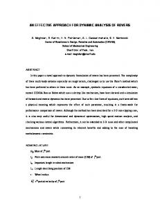
gives rise to an increase in the number of the NF data when the AUT geometry departs from the spherical one. To overcome these drawbacks, a new NF-FF transformation technique with helicoidal scan, which makes use of a proper AUT modelling, has been developed in [13]. Such a modelling is obtained by considering the AUT as enclosed in the smallest surface S formed by a cylinder ended in two half-spheres (see Fig. 1). Accordingly, it is particularly suitable to deal with elongated antennas, but remains quite general and contains the spherical modelling as particular case. z
d
S
y ( h ) being a phase function to be determined. The bandlimitation error, occurring when the reduced voltage is approximated by a bandlimited function, results to be negligible as the bandwidth exceeds a critical value Wh [6]. Accordingly, it can be effectively controlled by choosing a bandwidth equal to c 'Wh , where c ' is an excess bandwidth factor slightly greater than unity for an electrically large AUT. The two-dimensional OSI algorithm for reconstructing the voltage from a nonredundant number of its samples collected by the probe along a proper helix has been obtained in [13], by developing a nonredundant sampling representation of the voltage on a helix, whose step must be chosen equal to the sample spacing required to interpolate the data along a generatrix. This target has been achieved by heuristically extending the rigorous approach in [10], valid when adopting the spherical AUT modelling, to the case of elongated antennas. In such a case, it is convenient to choose the surface S coincident with a cylinder of height h' ended in two half-spheres of radius a' (see Figs. 1 and 2).
h
h' x
z
y
P1 P(h)
2a'
s'1
R1
h
a' s' J h' O
x
Fig. 1 Helicoidal scanning
R2
This work provides the experimental validation of such an innovative NF–FF transformation technique. The experimental validation has been carried out at the laboratory of antenna characterization of the University of Salerno, where an advanced cylindrical NF measurement facility supplied by MI Technologies is available.
P1
s'2
C'
Fig. 2 Relevant to a cylinder generatrix
II. HELICOIDAL SCANNING FOR ELONGATED ANTENNAS For reader’s convenience, the main results concerning the reconstruction of the voltage from the knowledge of a nonredundant number of its samples acquired by the measurement probe along a helix [13] are summarized in the following. Let us consider an AUT and a non directive probe scanning a proper helix lying on a cylinder of radius d (see Fig. 1) and adopt the spherical coordinate reference system (r , J , j ) to denote the observation point P. Since the voltage V measured by such a probe has the same effective spatial bandwidth of the field, the theoretical results on the nonredundant representation of EM fields [6] can be applied to it. Accordingly, if the AUT is enclosed in a convex domain bounded by a surface S with rotational symmetry and the observation curve is described by a proper analytical parameterization r = r (h ) , it is convenient to introduce the probe “reduced voltage” V˜ (h ) = V (h ) e jy (h )
(1)
By adopting Wh = b l' /2p (l' being the length of the intersection curve C ' between the meridian plane and S), the phase function y and the parameterization h to be used for describing a generatrix become [6], [13]:
y = ( b 2)[ R1 + R2 + s1' - s2' ]
(2)
h = ( p l')[ R1 - R2 + s1' + s2' ]
(3)
where (see Fig. 2)
R1,2 =
l' = 2 (h' + p a')
(4)
( z m h'/2)2 + d 2 - a'2
(5)
are the distances from P to the tangency points P1,2 on C ', and s1',2 are their arclength coordinates given by:
Ê a' d + R1 ((h'/2) - z ) ˆ s1' = a'sin -1 Á ˜ Ë ¯ R12 + a'2
(6)
È Ê a' d + R2 ((h'/2) + z ) ˆ ˘ s2' = h' +a' Í p - sin -1 Á ˜˙ Ë ¯˚ R22 + a'2 Î
(7)
It must stressed that, in any meridian plane, the curves y = const and h = const become those displayed in Fig. 3, instead of the circumferences and radial lines of the spherical modelling.
(2), and the parameter x is b / Wx times the curvilinear abscissa of the projecting point that lies on the spiral wrapping the surface S . Moreover, as suggested in [13], Wx must be chosen equal to b / p times the length of the spiral wrapping the surface S from pole to pole. Namely, the spiral, g and x are such that they coincide with those relevant to the spherical modelling, when the surface S leads to a sphere. In light of these results, the voltage at any point Q of the helix can be recovered via the OSI expansion [13]: m0 + p
V˜ (x ) =
Â
V˜ (xm ) W M (x - x m ) D M '' (x - x m )
(9)
m = m 0 - p +1
where m0 = Int[(x - x (fi )) Dx ] is the index of the sample nearest (on the left) to the output point, 2p is the number of retained samples V˜ (x m ) , and
xm = x (fi ) + mDx = x (fi ) + 2 p m (2 M " +1)
(10)
with M " = Int( c M ' ) + 1 and M ' = Int( c 'Wx ) + 1. Moreover, DM " (x ) =
y = const.
W M ( x) =
h = const.
Ï x = d cos(f - fi ) Ô Ì y = d sin(f - fi ) Ô z = d cot [J (h )] Ó
(8)
wherein f is the angular parameter describing the helix, f i is the value of f at P0 , and h = kf . Such a helix is obtained by projecting a proper spiral wrapping the surface S modelling the AUT on the scanning cylinder via the curves at h = const [13]. In order to allow the two-dimensional interpolation, the step of the spiral must be equal to the sample spacing needed to interpolate the voltage along the generatrix. Then, the parameter k is such that the step, determined by two consecutive intersections (at f and f + 2p ) with a given generatrix, is chosen equal to the sample spacing Dh = 2 p (2 N " +1) , where N " = Int( c N ') + 1, being N ' = Int( c 'Wh ) + 1. Accordingly, being Dh = 2 pk , it follows that k = 1 (2 N "+ 1) . The function Int( x ) gives the integer part of x and c > 1 is an oversampling factor needed to control the truncation error. The phase function g and the parameterization x to be used for obtaining a nonredundant sampling representation along the helix can be determined according to the heuristic approach proposed in [13]. In particular, by generalizing the corresponding relations valid when adopting the spherical AUT modelling, the phase function g coincides with y defined in
[
(
(11)
)2 ]
TM -1 + 2 cos( x / 2) cos(x /2)
Fig. 3 Curves y = const and h = const
The equations of the helix, when imposing its passage through a fixed point P0 of the generatrix at j = 0, are:
sin((2 M " +1)x 2 ) (2 M " +1) sin ( x 2)
TM [ -1 + 2 cos 2 (x /2)]
(12)
are the Dirichlet and Tschebyscheff Sampling functions, wherein TM (x ) is the Tschebyscheff polynomial of degree M = M " - M ' and x = pDx . The OSI formula (9) can be used to evaluate the “intermediate samples”, namely, the voltage values at the intersection points between the helix and the generatrix passing through a given point P. Once these samples have been evaluated, the NF data required by the probe compensated NF–FF transformation technique with cylindrical scanning [14] can be reconstructed via the following OSI expansion: n0 + q
V˜ (h(J ),j) =
Â
V˜ (hn )W N (h - h n) DN " (h - h n)
(13)
n = n0 - q +1
where n0 = Int[(h - h0 ) / Dh ] , V˜ (h n ) are the voltage intermediate samples,
hn = hn (j ) = h(fi ) + kj + n Dh = h0 + n Dh
(14)
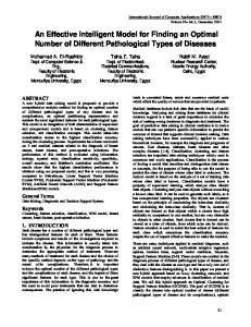
and all the other symbols have the same or analogous meaning as in (9). III. EXPERIMENTAL RESULTS The technique described in the previous section has been experimentally assessed in the anechoic chamber of the antenna characterization laboratory of the University of Salerno, where an advanced cylindrical NF measurement facility supplied by MI Technologies is available. The chamber, whose
Output voltage amplitude (dB)
Fig. 4 Photo of the antenna under test
-20 -30 -40
p= q=6 c = 1.20 c' = 1.35
-50 -60 -70 -80 -90 -100 -80 -60 -40 -20
0
20
40
60
80 100 z (cm)
Fig. 5 Amplitude of the probe voltage on the generatrix at j = 0∞ . Solid line: measured. Crosses: interpolated.
Output voltage amplitude (dB)
dimensions are 8 m ¥ 5 m ¥ 4 m , is provided with pyramidal absorbers ensuring a background noise due to the residual reflections lower than – 40 dB. It is equipped with a rotating table and a vertical scanner, so that, by properly matching their movements, the NF data can be acquired at any point on the cylindrical surface surrounding the AUT. The rotating table MI-6111B, mounted with its rotary axis parallel to the vertical scanner, ensures an angular precision of ± 0.05∞ , whereas the vertical scanner, whose height is 240 cm, is characterized by a linear precision of ± 0.005 cm . The controller MI-4190 is used to control the positioners motion and is completed by the option MI-4193, so that it is able to simultaneously drive both the positioners. Moreover, it is connected to a host computer by means of a IEEE-488 interface. The amplitude and phase measurements are performed by means of a computer-controlled vectorial network analyzer Anritsu 37247C, characterized by wide dynamic range, high sensitivity and linearity over the range from 40 MHz to 20 GHz. The probe is an open-ended rectangular waveguide MI-6970-WR90, whose end is tapered for minimizing the diffraction effects. The AUT, located in the plane x = 0, is a resonant slotted waveguide array 37.7 cm long, fed at the center of the bottom broad wall by a coaxial line, operating at 10 GHz (see Fig. 4). It has been obtained from a WR-90 waveguide by cutting in it two rows each of 10 round-ended slots. These rows are at the same distance from the center line of the broad waveguide wall. The slots are longitudinally directed and uniformly spaced by l g / 2, wherein l g is the guide wavelength. According to the sampling representation described in the Section II, the AUT has been modelled as enclosed in the surface S formed by a cylinder of height h' = 37.5 cm ended in two half-spheres of radius a' = 2.5 cm . The probe output voltages have been acquired on a helix lying on a cylinder with h = 237 cm and d = 18 cm. In order to assess the effectiveness of the two-dimensional OSI expansion, the amplitudes of the recovered probe voltage relevant to the generatrices at j = 0° and j = 45° are compared in Figs. 5 and 6 with those directly measured on the same generatrices. As can be seen, the reconstructions are everywhere very good, save for the peripheral zone (below about –60 dB), wherein the error is caused both by the truncation of the scanning zone and the residual environmental reflections. Note that, due to the filtering properties of the interpolation functions, the spatial harmonics relevant to the noise sources outside the AUT spatial bandwidth are cut away. This reflects in a smoother behaviour of the reconstructed voltage with respect to the measured one. The comparison between the phase of the recovered voltage and the measured one on the generatrix at j = 0° is also reported in Fig. 7. In order to improve the readability of the plot, such a comparison is shown only in the range [0 cm, 100 cm]. It is worth noting that all the reported reconstructions have been obtained by using c ' = 1.35 , c = 1.20 , and p = q = 6. In order to assess the overall effectiveness of the proposed NF–FF transformation technique, the FF pattern in the principal planes H and E, reconstructed from the acquired helicoidal
-20 -30 -40
p= q=6 c = 1.20 c' = 1.35
-50 -60 -70 -80 -90 -100 -80 -60 -40 -20
0
20
40
60
80 100 z (cm)
Fig. 6 Amplitude of the probe voltage on the generatrix at j = 45∞ . Solid line: measured. Crosses: interpolated.
NF data, is compared in Figs. 8 and 9 with that obtained by using the software package MI-3000 from the knowledge of the data directly measured on the classical cylindrical grid. The same software has been used to get the FF reconstructions from the helicoidal NF data. To this end, the two-dimensional OSI algorithm has been employed for recovering the cylindri-
(880) needed by the nonredundant NF–FF transformation with cylindrical scanning [15] and is significantly less than that needed by the NF helicoidal scanning technique [16], which requires the same number of the classical cylindrical approach. As a conclusion, the helicoidal scan retains the accuracy of the classical cylindrical approach and allows one to remarkably reduce the time required for the data acquisition.
Output voltage phase (degrees)
200 150 100 50 0 -50
p= q=6
-100
c = 1.20
-150
c' = 1.35
[1]
-200 0
20
40
60
80
100 z (cm)
Fig. 7 Phase of the probe voltage on the generatrix at j = 0∞ . Solid line: measured. Crosses: interpolated.
Field amplitude (dB)
20
[2] [3] [4]
p=q=6 c = 1.20
10
[5]
c ' = 1.35 0
[6]
-10 -20
[7] -30 25
50
75
100
125 150 Q (degrees)
[8]
Fig. 8 H-plane pattern. Solid line: reference. Crosses: reconstructed from NF data acquired via helicoidal scanning. [9] 25 Field amplitude (dB)
20
[10]
15 10
[11]
5
p=q=6
0
c = 1.20
-5
c ' = 1.35
-10 -180 -135
-90
-45
0
[12]
45
90
135
180
F (degrees)
[13]
Fig. 9 E-plane pattern. Solid line: reference. Crosses: reconstructed from NF data acquired via helicoidal scanning.
cal data required to carry out the NF–FF transformation. As can be seen, in both the planes, there is a very good agreement, thus assessing the validity of the proposed NF–FF transformation with helicoidal scanning. It is interesting to compare the number of data (788) needed by such a NF–FF transformation with that (5 120) required by the traditional cylindrical NF scanning to cover the same scanning zone. Note that this number is comparable with that
[14] [15]
[16]
REFERENCES A.D.Yaghjian, “An overview of near-field antenna measurements,” IEEE Trans. Antennas Propagat., vol. AP-34, pp. 30-45, January 1986. “Special Issue on near-field scanning techniques,” IEEE Trans. Antennas Propagat., vol. AP-36, pp.727-901, 1988. C.Gennarelli, G.Riccio, F.D’Agostino, and F.Ferrara, Nearfield – far-field transformation techniques, vol. 1, CUES, Salerno, Italy, 2004. C.Gennarelli, G.Riccio, F.D’Agostino, F.Ferrara, and R. Guerriero, Near-field – far-field transformation techniques, vol. 2, CUES, Salerno, Italy, 2006. O.M.Bucci and G.Franceschetti, “On the spatial bandwidth of scattered fields,” IEEE Trans. Antennas Propagat., vol. AP-35, pp. 1445-1455, December 1987. O.M.Bucci, C.Gennarelli, and C.Savarese, “Representation of electromagnetic fields over arbitrary surfaces by a finite and nonredundant number of samples,” IEEE Trans. Antennas Propagat., vol. 46, pp. 351-359, March 1998. O.M.Bucci, C.Gennarelli, and C.Savarese, “Optimal interpolation of radiated fields over a sphere,” IEEE Trans. Antennas Propagat., vol. AP-39, pp. 1633-1643, 1991. R.G.Yaccarino, L.I.Williams, and Y.Rahmat-Samii, “Linear spiral sampling for the bipolar planar antenna measurement technique,” IEEE Trans. Antennas Propagat., vol. AP-44, pp. 1049-1051, July 1996. O.M.Bucci, C.Gennarelli, G.Riccio, and C.Savarese, “Nonredundant NF–FF transformation with helicoidal scanning,” JEMWA, vol. 15, pp. 1507-1519, 2001. F.D’Agostino, C.Gennarelli, G.Riccio, and C.Savarese, “Theoretical foundations of near-field–far-field transformations with spiral scannings,” Progress in Electromagn. Res., PIER 61, pp. 193-214, 2006. O.M.Bucci, F.D’Agostino, C.Gennarelli, G.Riccio, and C.Savarese, “Probe compensated FF reconstruction by NF planar spiral scanning,” IEE Proc. - Microw., Antennas Propagat., vol. 149, pp. 119-123, 2002. O.M.Bucci, F.D’Agostino, C.Gennarelli, G.Riccio, and C.Savarese, “NF–FF transformation with spherical spiral scanning,” IEEE Antennas Wireless Propagat. Lett., vol. 2, pp. 263-266, 2003. F.D’Agostino, F.Ferrara, C.Gennarelli, R.Guerriero, M.Migliozzi, and G.Riccio, “NF – FF transformation with helicoidal scanning: an effective source modelling for elongated antennas,” Int. Jour. of Microw. and Opt. Technol. vol. 3, pp. 275-282, July 2008. W.M.Leach Jr. and D.T.Paris, “Probe compensated NF measurements on a cylinder,” IEEE Trans. Antennas Propagat., vol. AP-21, pp. 435-445, July 1973. O.M.Bucci, C.Gennarelli, G.Riccio, and C.Savarese, “NF– FF transformation with cylindrical scanning: an effective technique for elongated antennas,” IEE Proc. - Microw., Antennas Propagat., vol. 145, pp. 369-374, October 1998. S.Costanzo and G.Di Massa, “Far-field reconstruction from phaseless near-field data on a cylindrical helix,” J. Electromagn. Waves Appl., vol. 18, pp. 1057-1071, 2004.