Phil. Trans. R. Soc. A (2008) 366, 3155–3173 doi:10.1098/rsta.2008.0090 Published online 23 June 2008
REVIEW
An efficient approach to converting three-dimensional image data into highly accurate computational models B Y P. G. Y OUNG 1, * , T. B. H. B ERESFORD -W EST 1 , S. R. L. C OWARD 1 , B. N OTARBERARDINO 1 , B. W ALKER 2 AND A. A BDUL -A ZIZ 3 1
School of Engineering, Computing and Mathematics, University of Exeter, North Park Road, Exeter EX4 4QF, UK 2 ARUP Campus, Blythe Valley Business Park, Solihull, West Midlands B90 8AE, UK 3 NASA Glenn Research Center, 21000 Brook Park Road MS 6-1, Cleveland, OH 44135, USA
Image-based meshing is opening up exciting new possibilities for the application of computational continuum mechanics methods (finite-element and computational fluid dynamics) to a wide range of biomechanical and biomedical problems that were previously intractable owing to the difficulty in obtaining suitably realistic models. Innovative surface and volume mesh generation techniques have recently been developed, which convert three-dimensional imaging data, as obtained from magnetic resonance imaging, computed tomography, micro-CT and ultrasound, for example, directly into meshes suitable for use in physics-based simulations. These techniques have several key advantages, including the ability to robustly generate meshes for topologies of arbitrary complexity (such as bioscaffolds or composite micro-architectures) and with any number of constituent materials (multi-part modelling), providing meshes in which the geometric accuracy of mesh domains is only dependent on the image accuracy (image-based accuracy) and the ability for certain problems to model material inhomogeneity by assigning the properties based on image signal strength. Commonly used mesh generation techniques will be compared with the proposed enhanced volumetric marching cubes (EVoMaCs) approach and some issues specific to simulations based on threedimensional image data will be discussed. A number of case studies will be presented to illustrate how these techniques can be used effectively across a wide range of problems from characterization of micro-scaffolds through to head impact modelling. Keywords: biomechanics; finite element; finite volume; image-based meshing; material characterization; orthopaedics
* Author for correspondence (
[email protected]). One contribution of 12 to a Theme Issue ‘The virtual physiological human: building a framework for computational biomedicine I’.
3155
This journal is q 2008 The Royal Society
3156
P. G. Young et al.
1. Introduction Computational modelling offers the prospect of providing both a better insight into a range of biomechanical problems and improved tools for the design of medical devices and the diagnosis of pathologies. Early biomechanical applications of the finite–element method (FE) were principally in orthopaedics. Owing to computational limitations, these early FE studies predominantly used two-dimensional or axisymmetric modelling (Rybicki et al. 1972; Svesnsson et al. 1977; Pedersen et al. 1982; Berkelmans et al. 1992) and, as a consequence, the geometric fidelity was relatively poor. As increased computational power became more widely available larger models became feasible and results from threedimensional models were increasingly reported in the literature (Crowninshield et al. 1980; Hampton et al. 1980; Carter et al. 1982; Vasu et al. 1982). More recently, considerable attention has been focused on the generation of high-fidelity models constructed from data obtained from three-dimensional imaging modalities such as computed tomography (CT) and magnetic resonance imaging (MRI; Taylor et al. 1996; Viceconti et al. 1998). However, most approaches to converting three-dimensional images into meshes for use in FE or computational fluid dynamics (CFD) analysis necessitate significant user interaction and often still involve some appreciable simplification of the model geometry (Cebral & Loehner 2001; Antiga et al. 2002). A major reason for the lack of automation is the use of traditional approaches to meshing in the model construction pipeline. These meshing techniques were developed to generate models from computer-assisted design (CAD) data and, quite naturally, they are based on generating volume discretizations starting from bounding surfaces. Most approaches mooted to date for generating three-dimensional volume meshes from image data have therefore involved an intermediary step of surface reconstruction, which is then followed by the use of these traditional CAD-based meshing algorithms (Viceconti et al. 1998; Schmitt et al. 2001; Wirtz et al. 2003)—a process which is time consuming, not very robust and can be virtually intractable for the complex topologies and geometries typical of much image data. CAD-based meshing techniques fail to exploit the fact that for three-dimensional imaging data surfaces are not explicitly defined but only implicitly as the surface boundaries of a segmented volume of interest. Exploiting this difference leads to a far more accurate, robust and direct approach that combines the geometric detection and mesh creation stages in one process. The field of three-dimensional physics-based simulation based on threedimensional imaging data is still relatively new and lies at the interface between a number of disciplines. An overview of popular meshing algorithms and more recently developed grid-based meshing approaches will be given with a discussion on relative advantages and disadvantages for use in generating meshes from imaging data. Some issues specific to image-based simulation are discussed and a number of case studies that serve to illustrate these issues, as well as to demonstrate the versatility of the proposed approach, are then presented. 2. On image-based model generation Data from three-dimensional imaging modalities generally consist of a regular Cartesian grid of greyscale data representing the relative signal strength Phil. Trans. R. Soc. A (2008)
3157
Review. Image-based meshing (a)
(b)
(c)
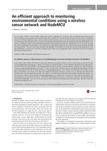
Figure 1. Reconstructions from CT scan of a dry cadaveric bone: (a) segmented volume of interest—voxel mesh, (b) surface mesh generated from marching cubes algorithm (no interpolation), (c) rendered view of surface mesh generated from marching cubes algorithm (including partial volume-based interpolation).
throughout the scanned volume obtained from the imaging modality. The most basic step that must be carried out is segmentation: that is, the identification of volumes of interest (VOI) within the image by classification of voxels into appropriate groups (bone, tendon, fat, muscle, etc.). Segmentation of medical images is an important area of active interest and the techniques available span the gamut from manually ‘painting’ voxels through to use of level set methods to identify contours (Sethian 1999). Clearly, the accuracy of any resultant model will be largely dependent on the accuracy of the initial segmentation and this will be a function not just of the image resolution but a number of other factors including noise, poor contrast between tissues and motion artefacts as well as, for semi-automated and manual approaches, inter-operator differences stemming from interpretation of images. In the following overview, it will be assumed that segmentation of all VOIs in the image has been carried out. Techniques for generating smooth high-quality volume meshes that are as faithful as possible to the boundaries implicitly defined by the original segmented data volumes will be discussed. (a ) Surface reconstruction from three-dimensional image data Where traditional meshing techniques are to be used on segmented threedimensional data, an initial step of reconstructing a suitably smooth surface representation must precede the application of meshing algorithms. One technique is to extract contours for the different slices and to loft a surface through these contours (Meyers et al. 1992). This approach suffers from significant drawbacks: the two-dimensional contouring usually involves fitting splines around the segmented two-dimensional cross sections based generally on manual selection of control points and this can lead to pronounced geometric discrepancies between bounding curve and parent segmented data; stacking the contours is problematic particularly where bifurcations occur as there is an inherent ambiguity regarding connectivity across the two slices, which needs to be resolved manually; and the approach cannot be applied to multiple VOIs as there is a loss of conformity of Phil. Trans. R. Soc. A (2008)
3158
P. G. Young et al.
surfaces at interfaces between different parts due to the curve fitting process. This approach leads to a significant loss of both surface detail and geometric accuracy and for anything but the most simple topologies reconstruction is virtually intractable. For the high-resolution imaging data obtained nowadays, by far the most popular approaches to surface extraction are based on the marching cubes algorithm (Lorensen & Cline 1987). The algorithm is based on considering the centre points of voxels in the image to be the vertices of a lattice or the grid of cubes. Based on whether a vertex is considered inside or outside the VOI, the edges bridging vertices inside and outside the object can be bisected and a configuration of triangular patches is assigned to each cube based on a predetermined surface tessellation for that ‘case’, which is stored in a look-up table. Indeed, there are only a finite number of ways (i.e. 28Z256) that a cube can be intersected by an isosurface and this can be further reduced by exploiting the rotational symmetries so that a much smaller number of cases need to be pre-defined (15 in the case of Lorensen & Cline’s original algorithm). The algorithm is extremely robust and faithful to the segmented VOI and provides C0 continuous triangulated surfaces that are guaranteed closed and manifold. The resultant surface extracted is used as the starting point for either generation of higher order CAD representation, such as non-uniform rational B-splines NURBS-based surfaces, or as triangulated bounding surfaces to be used for meshing using, for example, advancing front (AF) or Delaunay meshing techniques. Clearly, where the image data are of continuously varying signal strength, such as a temperature field, improved accuracy and smoothness can straightforwardly be obtained using exactly the same approach but intersecting at appropriately distanced interpolation points between vertices rather than simply bisecting the edges between vertices. While a priori, this approach may not seem applicable to image data obtained from scanning discrete structures, such as a CT scan of an engine, if certain conditions are met, then the measured signal strength at the interface between the structure and the background, say air, will reflect the percentage of the structure ‘occupying’ that voxel region—this is sometimes termed partial volume effect. When this is the case, the surface extraction from the marching cube using interpolation values is not only appreciably smoother but has enhanced fidelity (sub-voxel accuracy). In figure 1, the original stepped surface of a segmented volume from a cadaveric bone CT scan as well as surfaces generated from the marching cube approach, both with and without the use of partial volume information, are shown—the dramatic improvement in surface smoothness with partial volume interpolated data can clearly be seen. Unfortunately, for many, if not most, medical image datasets, this is not the case; segmentation is not principally based on thresholding and the resultant segmented data often consist of multiple VOIs with multiple areas of contact with one another—in effect, one is dealing with a stack of binary VOIs. The challenge then is to generate smooth surfaces that are faithful to the original segmentation. In the strictest sense for marching cube-based reconstructions, this requires the isosurfaces to be constrained to pass between the ‘in’ and ‘out’ vertices and interpolation points, both across conforming interfaces and at the intersection between three or more parts, need to be common to all VOIs. This ensures ‘image-based’ geometric and topological accuracy is achieved and to this end a multi-part smoothing algorithm has been implemented based on a reworking of the algorithms proposed by Taubin (2000). Phil. Trans. R. Soc. A (2008)
Review. Image-based meshing
3159
A significant drawback of the original marching cube algorithm is that it cannot handle cases in which more than two VOI meet (the so-called three-part junctions). This is a more limiting restriction than it might appear at first since the background needs to be considered as a part or VOI as well; for example, the intersection between two structures and the air cannot be reconstructed. However, two of the present authors ( P.G.Y. and T.B.H.B.-W.) have extended the marching cube algorithm to handle the intersection of up to eight different VOIs meeting at a junction (the maximum number that can meet in a Cartesian grid). This will be explained in more detail below when volume meshing based on marching cubes is discussed in §2c. (b ) Automated unstructured three-dimensional mesh generation: traditional techniques Unstructured three-dimensional mesh generation techniques can be broadly divided into hexahedral (hex) and tetrahedral (tet) mesh generation. To date, no techniques have been developed which can robustly mesh a single VOI of arbitrary geometry and topology with good-quality hex elements—let alone multiple VOIs. This is due to the strict nodal connectivity requirements that effectively constrain the hex mesh structure to consist of either stacks of elements or closed loops. Although techniques for hex meshing of CAD geometries have been developed (Armstrong 1995; Smith 1996; Liu & Gadh 1997), they are rarely fully automated requiring sometimes significant user interaction. To construct a pure hex mesh for the typically complex geometries and topologies of natural structures using the current state of the art in the field is difficult at best and often intractable. For a comprehensive review of techniques for hex meshing, the reader is referred to the excellent paper by Blacker (2001). For tet mesh generation, the two most common and widely adopted approaches to automated unstructured mesh generation are the AF approach and Delaunay tetrahedralization. Advancing Front. In the AF approach (van Phai 1982; Peraire et al. 1987; Lo ¨hner & Parikh 1988; Jin & Tanner 1991; Lo ¨hner et al. 1992), an initial surface triangular discretization is used as the starting point and additional nodes are added on the inside of the domain to generate a first layer of tetrahedra. This is then followed by another set of nodes forming another layer of tetrahedra piggy backing on the first, hence the name ‘advancing front’. Clearly, as the fronts move, there is a requirement to check whether the advancing fonts are coming together and poor element qualities can result where the fronts collide. The principal drawbacks are that success of the technique in generating meshes with low distortion is dependent on (i) an initial high-quality triangulated surface with appropriately sized surface element distribution and (ii) having sufficient ‘room’ to advance the front. Generation of appropriate surface discretizations for the AF becomes nontrivial when the surfaces are non-manifold involving multiple domains. Delaunay meshing. Delaunay meshing (Cavendish et al. 1985; Shenton & Cendes 1995) is an alternative technique that starts from a distribution of points within a convex hull. A Dirichlet tessellation of the domain is generated; this consists of polyhedral cells (Voronoi cells) enclosing each distributed point and each of these cells has the property that any point within the polyhedron is closer to its generating point than to the generating point of any other polyhedron. Phil. Trans. R. Soc. A (2008)
3160
P. G. Young et al.
Connecting the generating points across the polyhedral boundaries results in a Delaunay tetrahedralization of the volume. The tetrahedra generated using this process have the interesting property that spheres circumscribing their vertices will not contain any other vertex point in the domain. The tetrahedralization procedures used in practice are often based on the algorithm proposed by Bowyer (1981): a tet or hex convex hull bounding an initial point distribution is defined, a Delaunay tetrahedralization is carried out and additional points are introduced removing all tetrahedra whose circumsphere encompasses the new point. The void created by the deletion of these tetrahedra is then re-tetrahedralized by connecting all vertices on the void faces to the new point and the process is then repeated with the introduction of a new point. Clearly, mesh refinement can be relatively easily carried out by controlling the spatial distribution and density of points. If the original defined bounding surface needs to be recovered accurately, the mesh is then constrained to match the geometric surface of the problem through a process of boundary recovery and in the process element qualities can be prejudiced. In particular, Delaunay meshing is prone to generation of sliver elements (Cavendish et al. 1985). For a thorough review of both AF and Delaunay meshing techniques, the reader is referred to the paper by Lo¨hner (1997) and a more recent review of Delaunay mesh construction by Dyer et al. (2007). (c ) Grid-based methods: voxel and volumetric marching cube (VoMaC ) meshing The meshing approaches described above depend on using a surface mesh as a starting point. For image data, the surfaces used would generally be based on surfaces extracted from a marching cube-derived approach but these surfaces may need to be further processed for meshing to be successful and this processing generally involves manual editing with a possible attendant loss of accuracy. Often what is required is manual repositioning of only a very small percentage of all the mesh surface nodes, which although tractable with small models, becomes quickly a daunting task with large three-dimensional meshes particularly with inner cavities and multiple parts. The meshing process can be greatly simplified and made significantly more robust by either altogether bypassing the surface generation stage (voxel approach) or tailoring the mesh generation to the original surface generation method used thereby collapsing both volume and surface mesh generation into a single process (as in the VoMaC approach). Recent developments and challenges in this field will be discussed below. (i) Voxel approach A simple direct approach first proposed by Keyak et al. (1990) is to combine the geometric detection and mesh creation stages in one process—a process which is often referred to as the voxel method. Once the voxels have been appropriately classified using any of a wide range of possible segmentation techniques into different masks (e.g. representing bone, muscle, tendons, etc.), these voxels are straightforwardly exported as hex elements. This approach has a number of advantages: implementation is trivial; the mesh is entirely made of hexahedra; element qualities are optimal (at least for isotropically sampled or resampled data); any number of different masks can be Phil. Trans. R. Soc. A (2008)
3161
Review. Image-based meshing (a)
(b)
6
7
5
6
7
5
4
4 2
2 3
1
3
1
0
0
Figure 2. Tetrahedral base case for: (a) cube with all vertices ‘in’ the object, i.e. no isosurface running through the model, and (b) a cube with single isosurface running through it.
(a)
(b)
(c)
(d )
Figure 3. Hex–tet ratio improvement and mesh coarsening techniques illustrated on a cylindrical volume model: (a) original voxel mesh; (b) tetrahedralized using VoMaCs; (c) tetrahedralized with internal hexahedral grid and surface tetrahedral elements resorbed, where possible, into hexahedra; (d ) same as in (c) but with octree-type decimation away from boundaries. Phil. Trans. R. Soc. A (2008)
3162
P. G. Young et al.
handled and conformity of meshes at interfaces is intrinsically guaranteed. In addition, because the meshing process is carried out directly from the imaging data, and there is a one-to-one correspondence between parent image sample values and elements, it is easy to assign inhomogeneous material properties to elements in one or more mesh domains based on the parent image signal strength. This approach has been used with some success to study the mechanical behaviour of cancellous bone (Fyhrie et al. 1992). There are, however, clearly a number of drawbacks to the voxel method. First and foremost, the surfaces of mesh domains, including interfaces where different domains meet, are clearly stepped. Beyond giving the models an unrealistic ‘Lego brick’ appearance, this will seriously prejudice a number of physics-based simulation results in particular where processes modelled are dependent on surface area (such as thermal transport, electromagnetic radiation and chemical diffusion) as the surface area will be appreciably overestimated. One of the central problems with the resultant inaccuracy in surface area is that it does not necessarily improve with finer resolution obtained by better scanning or super-sampling the image data—in effect, there is no guaranteed convergence to the correct surface area with mesh refinement (e.g. for a sphere meshed as cubic voxels as the element side length over radius of sphere ratio tends to zero, the p ratio ffiffiffi of the voxel mesh surface area to that of a perfect sphere will tend to 3= 3 z1:73—in other words, in the limit, the surface area is overestimated by more than 70%). Additionally, in structural mechanics, the stepped boundary representation will preclude the analysis of sliding at mesh interfaces as the mesh domains are effectively interdigitated. A second drawback is the lack of mesh size control. The basic approach does not adapt element size to features or allow for localized mesh refinement as the spatial discretization is uniform over the whole domain and is determined by the sampling rate. Although arbitrarily fine meshes can be obtained straightforwardly by super-sampling the image data, where only localized refinement is required this is a very inefficient approach and rapidly leads to very large and computationally intractable problems. (ii) VoMaCs and extended VoMaCs The marching cubes approach was adapted (Mueller & Ruegsegger 1994) for the generation of volume meshes by having for each base case the surface hexahedral parent element discretized into tetrahedra such that the surface faces were compatible with the marching cube faces—in other words, for every base case, rather than simply determine surface triangulations, a complete tetrahedralization of the hexahedral volume is pre-computed and provided in a look-up table. The technique effectively combines most of the advantages of the voxel-based method but overcoming the issue of having stepped mesh surface definition. However, in one particular aspect, the VoMaC approach is not an improvement on the voxel approach as it is applicable only to single mesh domains (or more precisely only to nested or multiple spatially unconnected domains), inheriting this limitation from the original marching cube surface extraction algorithm on which it is based. Phil. Trans. R. Soc. A (2008)
Review. Image-based meshing
3163
Table 1. Comparison of distortion metrics for mesh generated using EVoMaC (CSCANFE, Simpleware Ltd 2006) and using an AF approach (ABAQUS, Inc. 2004). (EVoMaC mesh was imported into ABAQUS and the mesh verification tool in ABAQUS CAE was used to generate mesh statistics.)
number elements number nodes shape factor
aspect ratio face corner
% elements !0.1 % elements !0.04 worst shape factor average worst aspect ratio worst maximum angle worst minimum angle
advancing front
EVoMaC
173 181 38 678 2.5% (4319) 1% 0.0000001Oworst 2.2 70 1748 0.68
127 600 26 200 0.11% (143) 0% 0.04 1.9 5 1398 128
Some of the disadvantages of the VoMaC approach have been addressed by developing suitable schemes and algorithms that have been implemented into a flexible mesher CSCANFE (Simpleware Ltd 2006) that is part of an integrated image processing and meshing environment SCANIP (Simpleware Ltd 2006). Multi-part meshing. Both the marching cubes surface generation approach and the VoMaC approach were extended by two of the present authors ( P.G.Y. and T.B.H.B.-W.) to take into account intersections between three or more parts. In Cartesian (voxelized) space, there are up to eight possible parts meeting at a vertex and the nominal number of base cases to be solved increases from 256 to 4096. If one starts with a five tetrahedral carving of a parent cube, the complexity is compounded by the need to have a so-called ‘black and white’ scheme in order to ensure not just nodal but face connectivity at interfaces between tetrahedralized cubes—this is deemed desirable to avoid incompatible displacement in structural finite-element analyses and is an absolute requirement for finite volume meshes. However, exploiting symmetries (rotational, mirroring, etc.) the number of cases can be brought down to 70 fundamental base cases. This development has allowed the extended VoMaC (EVoMAC) approach to have all the advantages of the voxel approach overcoming the limitations of single part meshing inherent in the original VoMaC approach. Both the fully tetrahedralized cube and an example terahedralization of a cube with an isosurface running through it are shown in figure 2. Improving hex/tet ratio. The resultant meshes can clearly either be all tet or mixed hex–tet. Internal voxels can be converted to hexahedra rather than tetrahedralized providing that care is taken in generating a layer of transitional elements at the tet to hex interfaces. This can be achieved using very simple transitional schemes including either combinations of pyramidal and tet elements or, where supported, polyhedral elements (cells for CFD). In addition, the hex– tet ratio can be further improved by converting the surface tetrahedra (those cut by an isosurface) to hexahedra for base cases that do not spawn additional nodes and thereby maintain an eight-noded hexahedral topology (figure 3c,d ) providing hex quality, as measured by appropriate distortion metrics, is sufficiently high. Phil. Trans. R. Soc. A (2008)
3164
P. G. Young et al. (a)
(b)
(c)
(d )
(e)
(f)
Figure 4. Foam samples meshed using (a) EVoMaC and (b) AF approaches. Surface tetrahedra with shape factors below 0.04 flagged on surface of mesh. (c– f ) Full foam model at various stages of compression resulting from impact loading simulation in LS-DYNA (LSTC 2003).
Mesh density control. As previously discussed, one drawback of voxel-based approaches is the uniformity of the element density throughout the mesh. A simple technique has been implemented to reduce element numbers by coarsening the mesh away from boundaries. This is essentially an octree-based approach and the process used is to identify and collect clusters of eight voxels within the interior and collapse them into larger (2!2!2) elements with appropriate transitioning tetrahedra to finer grid (figure 3d ). The process can be repeated with clusters of eight larger hexahedra amalgamated, always ensuring adequate transitions. The technique can be reasonably effective where there is a large volume to surface area ratio and a small voxel side length to characteristic length ratio. Interestingly, it can be shown that this scheme will always reduce the number of nodes (vertices) in the problem but may not always reduce the Phil. Trans. R. Soc. A (2008)
3165
Review. Image-based meshing
percentage of total elements (%)
30 25 20 15 10 5 0
0.2
0.6 0.4 cell squish index
0.8
1.0
Figure 5. Comparison of distribution of Cell Squish Index (1 is poor, 0 is good) for mesh generated using EVoMaC (CSCANFE, Simpleware Ltd 2006) and using a Delaunay tetrahedralization (GAMBIT, Fluent, Inc. 2008). EVoMaC mesh was imported into FLUENT and the mesh verification tool in FLUENT ( Fluent, Inc. 2004) was used to generate mesh statistics. Dashed line, Delaunay; dotted line, EVoMaC.
number of elements. Nonetheless, the approach is rudimentary and there is still a lack of appropriate techniques for element size control in the current EVoMaC approach in order to better capture geometric complexity, to better model field parameter of interest in a localized region of interest and to more effectively decrease the element numbers. 3. Illustrative case studies A number of short case studies will be carried out in order to illustrate some of the issues raised and concepts discussed above and to demonstrate the range of problems which can be treated robustly using the EVoMaC approach. (a ) Open-celled foam structure: single part meshing Although most three-dimensional imaging techniques were initially developed for use as patient diagnosis tools, they have been adopted in the materials’ research field for qualitative and quantitative characterizations of the microstructural behaviour of a range of natural and man-made materials including bioscaffolds. More recently, the use of these images as the basis for generating finite-element and finite volume models for use in physics-based simulations has gained ground (Abdul-Aziz et al. 2006; Berre et al. 2006; Watson et al. 2006; Notarberardino et al. 2008). Imaging and segmentation. High-resolution three-dimensional micro-CT scan data of a scaffold structure were obtained, and the data were straightforwardly segmented using threshold and flood fill tools in SCANIP (Simpleware Ltd 2006). Mesh generation and quality comparison. A three-dimensional triangulated surface mesh using the marching cubes implementation in SCANIP (Simpleware Ltd 2006) was generated and exported as an STL file for meshing within GAMBIT (Delaunay-based mesher, Fluent, Inc. 2008) and the same surface mesh was Phil. Trans. R. Soc. A (2008)
3166
P. G. Young et al.
exported to ABAQUS (ABAQUS, Inc. 2004) for volume meshing using their AF mesher. In addition, a three-dimensional volumetric mesh was generated using EVoMaC techniques implemented in CSCANFE (Simpleware Ltd 2006) and exported as an ABAQUS input deck (.inp) as well as a FLUENT (Fluent, Inc. 2004) format file (.msh). Mesh qualities based on metrics provided by ABAQUS CAE were used to compare the EVoMaC with the AF-generated meshes and the results are given in table 1. The meshed structures are shown in figure 4 with shape factors falling below a threshold of 0.04 highlighted for the AF mesh. Although the AF successfully meshed the domain, the mesh quality was very poor with element side ratios as high as 70. In figure 5, the cell squish distribution, a measure of cell quality for CFD applications, for the Delaunay meshed volume is plotted against the results obtained from the EVoMaC approach and again the latter approach is seen to provide a better quality mesh. A range of different quality metrics were checked but owing to space limitations the results will be omitted here. Analysis. A model based on a larger sample was generated using EVoMaC in order to carry out dynamic and quasi-static nonlinear finite-element analysis using the software package LS-DYNA (LSTC 2003) to simulate large deformations using an explicit solver. The full-size EVoMaC model was compressed between two rigid platens and foam-to-foam contact was modelled using a self-contact algorithm with zero friction. The finite-element analysis simulating compression (approx. 85% strain) took over 8.5 hours on a dual Intel Xeon processor PC cadenced at 2.8 GHz and the foam at various stages of compression is shown in figure 4. (b ) Instrumented hip: multipart modelling Imaging and segmentation. A CT scan of in-plane resolution 0.77 mm and slice-to-slice separation 1 mm was resampled isotropically to 1 mm in all directions using linear interpolation, a metal artefact reduction filter was applied and six masks were segmented in SCANIP (Simpleware Ltd 2006) as shown in figure 6 using a combination of thresholding, flood filling and manual painting. Mesh generation and quality comparison. Multi-part surface meshes (in STL format for GAMBIT and as multiple surface triangular element input deck for ABAQUS) were exported for a small subset of the data in order to compare image-based meshing of multiple domains including three-part intersections with different meshing algorithms. The surface meshes used as a starting point for volume meshes in GAMBIT (Fluent, Inc. 2008) and ABAQUS (ABAQUS, Inc. 2004) were generated using algorithms implemented in CSCANFE (Simpleware Ltd 2006) and were smooth, of high surface element quality and perfectly conforming. A full volumetric mesh was also generated based on the same data and conforming to the same surface mesh in CSCANFE and is shown in figure 6c (note that the surface faces shown on this mesh are identical to the input surface meshes used in GAMBIT and ABAQUS). Both ABAQUS and GAMBIT failed to mesh the multi-part surface meshes with volume meshes: in ABAQUS, errors occurred at the location of the three-part junction even after selecting different subsets of the image (but keeping three-part junction problem; figure 7). Clearly, such three-part problems can be, and are indeed routinely, meshed using AF and Delaunay algorithms; however, this is not usually starting from a surface discretization generated from image data. Again, undoubtedly, the multi-part Phil. Trans. R. Soc. A (2008)
Review. Image-based meshing
3167
triangulated surface could be modified or remeshed to allow volume meshing using these algorithms. However, it is unclear to the authors how this can be done robustly and automatically using current state of the art (i.e. given arbitrary multi-part segmented image data can surfaces be generated which are guaranteed to be meshable using AF and Delaunay?). This is where the EVoMaC approach excels; regardless of the geometric and topological complexity and the number of segmented VOIs, the data can be meshed robustly and accurately. This is as a direct result of the fact that with the EVoMaC approach adequate element qualities are in effect ensured a priori as they all are based on a finite pool of mesh discretization cases (the base cases). Convergence study. There is an important and fundamental difference between meshes generated from CAD data and meshes generated from reverse engineering image data. In the case of CAD data, the geometric accuracy of the solid model is usually not in question. In order to ensure that simulation results have converged, the field parameter of interest, for example the stress at a point, is plotted for meshes of increasing density (or meshes using higher order elements) until the numerical predictions are shown to be relatively insensitive to further refinement. Alternatively, more sophisticated, and less computationally expensive, methods of ensuring convergence of finite-element analysis results can be applied. As with CAD-based models, this check must also be carried out for image-based models; however, there is a further need to ensure that the simulation results are not affected by inaccuracies in the recovery of the geometry, and possibly topology, of the original physical object from the image data. Indeed, unlike for CAD, in image-based models, the geometry is inferred approximately from a finite number of sampling points. It is therefore very important to ensure that the simulation results, the field parameters of interest, are not just insensitive to mesh density but also to the image sampling rate—this could be termed convergence to geometry. In order to carry out a mesh density convergence, the original CT data were resampled to produce a number of different FE models with resolutions from 1 mm (219 470 nodes) to 2.5 mm (22 286 nodes), a model was also produced from the 2 mm (39 337 nodes) model using higher order elements (267 664 nodes). The models were then simulated under four-point bending and strains were analysed across four areas that corresponded to the areas of the strain gauges used for comparison between the experimental sample and FE models. As the sampling rate is increased to produce a higher resolution image, both the mesh density and the geometrical accuracy of the models are increased. This produces a dual convergence to both the field parameter of interest and the geometry. An acceptable level of convergence was demonstrated with an average of 0.49% difference in strains between models with 219 470 and 164 737 nodes. The model produced with higher order elements showed an average difference of 5.8% between 39 337 and 267 664 nodes, with the same geometry. This suggests that the strain is relatively insensitive to the mesh density and more heavily influenced by the geometrical accuracy. Numerical convergence studies provided strong evidence of the robustness of the solutions obtained: models with significantly different mesh densities and based on different image resolutions were generated and good agreement was obtained between stress and strain responses in all the different constituent components of the model (bone, cement, cup and implant). In effect, this provides a degree of confidence that numerical Phil. Trans. R. Soc. A (2008)
3168
P. G. Young et al.
(a)
(b)
(c)
Figure 6. CSCANFE meshes: full model (proximal femur, hemi-pelvis, acetabular cup and cement bed, implant and cement mantle) shown (a) opaque and (b) transparent. (c) Small subset of model used for comparative mesh generation using EVoMaC, AF and Delaunay approaches.
results obtained were prejudiced by neither the approximations in the representation of the field parameter variation throughout the system nor the inherent approximation in the geometric representation of the mesh domains. Interestingly, this also forms a check that the variation in the inhomogeneity in the material properties of the bone is captured/modelled at a fine enough resolution not to prejudice the results. However, although these checks of the validity of the simulation results are necessary conditions for ensuring the validity of the model, they are not sufficient as any errors in assumed boundary conditions, loads, and Hounsfield to Young’s modulus mapping function would all influence the results significantly. Metrology study. The relationship between the scan resolution and the dimensional accuracy of FE models was explored. Measurements were taken at 14 different locations on a cadaveric femur and compared with FE models produced from a CT scan of the same femur. The original CT data were resampled to produce a number of FE models with isotropic resolutions between 0.8 and 2.5 mm. It was shown that the dimensional difference between the Phil. Trans. R. Soc. A (2008)
Review. Image-based meshing (a)
(b)
(c)
(d)
3169
Figure 7. Full volumetric reconstruction from in vivo MRI scan shown in (a). (b–d ) Different views of full three-dimensional volume finite-element reconstruction using the EVoMaC approach in C SCAN FE (Simpleware Ltd 2006). Element boundaries are not shown for the sake of visual clarity.
physical specimen and the FE models produced from scans of the specimen is within two times the resolution of the scan data, with an average difference of 0.8 times the scan resolution. (c ) Head model: multipart and topologically complex meshing As a final illustration of the potential of the EVoMaC approach for generating sophisticated finite-element meshes from high-resolution image data, a threedimensional T1-weighted acquisition of the head and neck of a young male Phil. Trans. R. Soc. A (2008)
3170
P. G. Young et al.
(26 years of age) was obtained. The head and the neck were segmented into 22 different masks including skull, cerebrospinal fluid, grey and white matters, cerebellum, eyes, orbital fat, intervertebral discs, vertebrae, fat, muscle and skin. Material properties can be assigned to this model based on signal strength for each of the different masks. Segmentation was carried out in SCANIP (Simpleware Ltd 2006) using a combination of techniques including thresholding, flood filling, manual painting as well as application of level set methods for the extraction of certain structures. Again surface meshes were generated from the same voxel segmentations and were submitted for meshing using AF and Delaunay meshers in ABAQUS (ABAQUS, Inc. 2004) and GAMBIT (Fluent, Inc. 2008), respectively, but this was entirely unsuccessful. By contrast, the model was meshed automatically without requiring any modification of either the segmented data or the surface reconstruction. In other words, and this is the key strength in the EVoMaC approach as applied to imaging data, once segmentation has been effected on the data, the generation process is robust, faithful to the segmentation and fully automated.
4. Conclusion Although a wide range of mesh generation techniques are available, these, on the whole, have not been developed with meshing from segmented three-dimensional imaging data in mind. Meshing from three-dimensional data presents a number of challenges but also unique opportunities so that a conceptually different approach can provide, in many instances, better results than traditional approaches. In this paper, we use a methodology based on VoMaC but addressing some of the limitations of that approach and in particular extending its use to meshing segmented data with an arbitrary number, as well as arbitrary spatial distributions, of VOIs. A simple approach to reducing the number of elements using an octree decimation scheme has been implemented as well as a method of further improving the hex–tet ratio using resorption of surface tets, where possible, into hex elements. The technique was shown to reliably and robustly provide good-quality meshes for both relatively simple domains through to complex problems with multiple VOIs. In the case of modelling complex topologies—with potentially hundreds of disconnected domains representing for example inclusions in a matrix— approaching the problem via CAD-based meshing approaches becomes increasingly more difficult. Indeed, using a CAD-based approach, each of the domains would need to be converted to an appropriately conditioned network of surface representations suitable for meshing, this would require ensuring the connectivity between multiple domains including domains potentially at the intersection between two or more domains as well as non-manifold volumes (i.e. volumes in which the domain is not described by a single surface). By contrast, treating the problem using a grid-based meshing approach is remarkably straightforward, robust, accurate and efficient. Indeed, once segmentation of the different phases present in the image has been carried out, a mesh can be generated automatically which is of image-based accuracy with domain boundaries of the finite-element model lying exactly on the isosurfaces. Phil. Trans. R. Soc. A (2008)
Review. Image-based meshing
3171
The different case studies presented demonstrate the potential across a very wide range of problems from the generation of structural models of scaffolds through to generating a model of a complete human head. In spite of their complexity and sophistication, full FE simulations were carried out on inexpensive and commonly available hardware platforms. The ease and accuracy with which models can be generated opens up a wide range of previously difficult or intractable problems to numerical analysis.
References ABAQUS, Inc. 2004 ABAQUS v. 6.5 user’s manual. Providence, RI: Rising Sun Mills. Abdul-Aziz, A., Saury, C., Bui Xuan, V. & Young, P. 2006 On the material characterization of a composite using micro CT image based finite element modelling. In Smart Structures and Materials and NDE, 26 February-2 March 2006, San Diego. Bellingham, WA: SPIE. Antiga, L., Ene-Iordache, B., Caverni, L., Cornalba, G. P. & Remuzzi, A. 2002 Geometric reconstruction for computational mesh generation of arterial bifurcations from CT angiography. Comput. Med. Imaging Graph. 26, 227–235. (doi:10.1016/S0895-6111(02)00020-4) Armstrong, C. G., Robinson, D. J., McKeag, R. M., Li, T. S., Bridhgett, S. J., Donaghy, R. J. & McGleenan, C. A. 1995 Medials for meshing and more. In Proc. 4th Int. Meshing Roundtable, Albuquerque, New Mexico, 16–17 October 1995. Berkelmans, W. A. M., Schreurs, P. J. G. & de Vree, J. H. P. 1992 Continuum damage mechanics for softening of brittle materials. Acta Mech. 93, 133–143. (doi:10.1007/BF01182579) Berre, C., Fok, S. L., Marsden, B. J., Babout, L., Hodgkins, A., Marrow, T. J. & Mummery, P. M. 2006 Numerical modelling of the effects of porosity changes on the mechanical properties of nuclear graphite. J. Nuclear Mater. 352, 1–5. (doi:10.1016/j.jnucmat.2006.02.037) Blacker, T. 2001 Automated conformal hexahedral meshing constraints, challenges and opportunities. Eng. Comput. 17, 201–210. (doi:10.1007/PL00013384) Bowyer, A. 1981 Computing Dirichlet tessellations. Comput. J. 24, 162–167. (doi:10.1093/comjnl/ 24.2.162) Carter, D. R., Vasu, R. & Harris, W. H. 1982 Stress distributions in the acetabular region-II. Effects of cement thickness and metal backing of the total hip acetabular component. J. Biomech. 15, 165 –170. (doi:10.1016/0021-9290(82)90248-2) Cavendish, J. C., Field, D. A. & Frey, W. H. 1985 An approach to automatic three-dimensional finite element generation. Int. J. Numer. Methods Eng. 21, 329 – 347. (doi:10.1002/nme. 1620210210) Cebral, J. R. & Loehner, R. 2001 From medical images to anatomically accurate finite element grids. Int. J. Numer. Methods Eng. 51, 985 –1008. (doi:10.1002/nme.205) Crowninshield, R. D., Brand, R. A., Johnston, R. C. & Milroy, J. C. 1980 An analysis of femoral component stem design in total hip arthroplasty. J. Bone Joint Surg. A 62, 68 –78. Dyer, R., Zhang, H. & Muller, T. 2007 Delaunay mesh construction. In Eurographics Symposium on Geometry Processing, ACM International Conference Proceeding Series, 257, pp. 273 –282. Fluent, Inc. 2004 FLUENT v. 6.2.16 user’s manual. Lebanon, NH: Fluent, Inc. Fluent, Inc. 2008 GAMBIT v. 2.3.16 user’s manual. Lebanon, NH: Fluent, Inc. Fyhrie, D. P., Hamid, M. S., Kuo, R. F. & Lang, S. M. 1992 Direct three-dimensional finite element analysis of human vertebral cancellous bone. Trans. Ann. Meeting Orthop. Res. Soc. 17, 551. Hampton, S. J., Andriacchi, T. P. & Galante, J. O. 1980 Three dimensional stress analysis of the femoral stem of a total hip prosthesis. J. Biomech. 13, 443 – 448. (doi:10.1016/00219290(80)90038-X) Jin, H. & Tanner, R. I. 1991 Generation of unstructured tetrahedral meshes by the advancing front technique. Int. J. Numer. Methods Eng. 31, 987–997. (doi:10.1002/nme.1620310511) Phil. Trans. R. Soc. A (2008)
3172
P. G. Young et al.
Keyak, J. H., Meagher, J. M., Skinner, H. B. & Mote Jr, C. D. 1990 Automated three-dimensional finite element modelling of bone: a new method. J. Biomed. Eng. 12, 389 –397. (doi:10.1016/ 0141-5425(90)90022-F) Liu, S. & Gadh, R. 1997 Automated hexahedral mesh generation: a knowledge based approach. In Proc. 6th Int. Meshing Roundtable, Park City, Utah, 13–15 October 1997. Albuquerque, NM: Sandia National Laboratories. Lo¨hner, R. 1997 Automatic unstructured grid generators. Finite Elem. Anal. Des. 25, 111–134. (doi:10.1016/S0168-874X(96)00038-8) Lo¨hner, R. & Parikh, P. 1988 Three-dimensional grid generation by the advancing front method. Int. J. Numer. Methods Fluids 8, 1135 –1149. (doi:10.1002/fld.1650081003) Lo¨hner, R., Camberos, J. & Merriam, M. 1992 Parallel unstructured grid generation. Comp. Methods Appl. Mech. Eng. 95, 343–357. (doi:10.1016/0045-7825(92)90192-M) Lorensen, W. E. & Cline, H. E. 1987 Marching cubes: a high resolution 3D surface construction algorithm. Comput. Graph. 21, 163–169. (doi:10.1145/37402.37422) LSTC (Livermore Software Technology Corporation). 2003 LS-DYNA v. 970 user’s manual. Livermore, CA: LSTC. Meyers, D., Skinner, S. & Sloan, K. 1992 Surfaces from contours. ACM Trans. Graph. 11, 228 –258. (doi:10.1145/130881.131213) Mueller, R. & Ruegsegger, P. 1994 Three dimensional finite element modeling of non-invasively assessed trabecular bone structures. J. Med. Eng. Phys. 17, 126 –133. (doi:10.1016/13504533(95)91884-J) Notarberardino, B., Young, P., Walker, B., Abdul-Aziz, A. & Seidler, G. 2008 Image based simulation of large strain deformation of open celled foams. Mater. Eval. 66, 60– 66. Pedersen, D. R., Crowninshield, R. D., Brand, R. A. & Johnston, R. C. 1982 An axisymmetric model of acetabular components in total hip arthroplasty. J. Biomech. 15, 305–315. (doi:10. 1016/0021-9290(82)90176-2) Peraire, J., Vahdati, M., Morgan, K. & Zienkiewicz, O. C. 1987 Adaptive remeshing for compressible flow computations. J. Comp. Phys. 72, 449–466. (doi:10.1016/0021-9991(87)90093-3) Rybicki, E. F., Simonen, F. A. & Weis Jr, E. B. 1972 On the mathematical analysis of stress in the human femur. J. Biomech. 5, 203–215. (doi:10.1016/0021-9290(72)90056-5) Schmitt, J., Meiforth, J. & Lengsfeld, M. 2001 Development of a hybrid finite element model for individual simulation of intertrochanteric osteotomies. Med. Eng. Phys. 23, 529 –539. (doi:10. 1016/S1350-4533(01)00085-6) Sethian, J. A. 1999 Level set methods and fast marching methods, evolving interfaces in computational geometry, fluid mechanics, computer vision, and materials science. Cambridge Monograph on Applied and Computational Mathematics. Cambridge, UK: Cambridge University Press. Shenton, D. N. & Cendes, Z. J. 1995 Three-dimensional finite element mesh generation using Delaunay tessellations. IEEE Trans. Magn. MAG-21, 2535–2538. Simpleware Ltd. 2006 SCANIP, CSCANFE and CSCANCAD software v. 2.0 reference guide. Exeter, UK: Innovation Centre. (http://www.simpleware.com) Smith, R. 1996 A novel cartesian grid method for complex aerodynamic CFD applications. In Proc. 5th Int. conf. on Numerical Grid Generation in Computational Field Simulations, Mississippi State University, April 2006. Svesnsson, N. L., Valliappan, S. & Wood, R. D. 1977 Stress analysis of human femur with implanted Charnley prosthesis. J. Biomech. 10, 581–588. (doi:10.1016/0021-9290(77)90038-0) Taubin, G. 2000 Geometric signal processing on polygonal meshes, State of the Art Report (STAR), Eurographics. Taylor, M. E., Tanner, K. E., Freeman, M. A. & Yettram, A. L. 1996 Stress and strain distribution within the intact femur: compression or bending? Med. Eng. Phys. 18, 122–131. (doi:10.1016/ 1350-4533(95)00031-3) van Phai, N. 1982 Automatic mesh generation with tetrahedron elements. Int. J. Numer. Methods Eng. 18, 237–289. (doi:10.1002/nme.1620180209) Phil. Trans. R. Soc. A (2008)
Review. Image-based meshing
3173
Vasu, R., Carter, D. R. & Harris, W. H. 1982 Stress distributions in the acetabular region-I. Before and after total joint replacement. J. Biomech. 15, 155–164. (doi:10.1016/0021-9290(82)90247-0) Viceconti, M., Zannoni, C. & Pierotti, L. 1998 TRI2SOLID: an application of reverse engineering methods to the creation of CAD models of bone segments. Comput. Methods Programs Biomed. 56, 211–220. (doi:10.1016/S0169-2607(98)00011-X) Watson, I. G., Lee, P. D., Dashwood, R. J. & Young, P. G. 2006 Simulation of the mechanical properties of an aluminum matrix composite using X-ray microtomography. Metall. Mater. Trans. A. 37A, 551– 558. (doi:10.1007/s11661-006-0027-9) Wirtz, D. C., Pandorf, T., Portheine, F., Randermacher, K., Schiffers, N., Prescher, A., Weichert, D. & Niethard, F. U. 2003 Concept and development of an orthotropic FE model of the proximal femur. J. Biomech. 36, 289–293. (doi:10.1016/S0021-9290(02)00309-3)
Phil. Trans. R. Soc. A (2008)