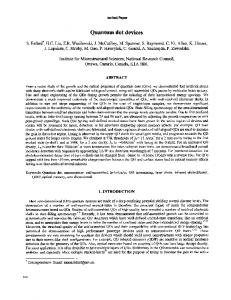
bandstructure of silicon, which leads to four fold degenerated single particle levels in the dot. Keywords: Si/SiO2 quantum dots, capacitance, self-consistent calculations, shell-filling effects. 1. ... available today, work is already under way to.
The sharp dips in the QDIP response corresponds to atmospheric ...... 'UflA f. 'Uiq ff. (8661). ZL1f. 'U. â¢IWT. SA4d. jddV. 'JJO14d. Wd. 'utuIIpM. Td. 'I°H. 0d. 'Pluvi.
Feb 15, 2017 - After retrieving the fabricated chips, in order to exhibit its correct functionality (produce .... hard to achieve [22]. ... number of distinct input data vectors for preventing data leakage and consequently key ... E. Around 50% HD: T
bility, which enables user to make a guided tour within the database. A pre-emptive cell search mechanism is introduced in order to prevent the corruption of ...
1,2,3 Department of Computer Engineering, Science and Research Branch, Islamic Azad University. Tehran ... ISSN (Online): 1694-0814 www.IJCSI.org .... Out AS S. BS. CS S. DS S. = +. +. +. (4). Table 1: 4:1 Multiplexer truth table. S1. S0. Out.
CMOS Logic, Low power, Full adder, and VLSI. 1. ... in the design of basic functional units for digital systems. ..... VLSI design: circuits and systemsâ, 2nd Edition.
[8] Yingtao Jiang, Al-Sheraidah, Yuke Wang, Edwin Sha and Jin-Gyun Chung, âA ... [14] Cihun-Siyong Alex Gong, Muh-Tian Shiue, Ci-Tong. Hong and Kai-Wen ...
By Definition a femtocell agnostically refers to a small wireless base station or
access point. " ... Source: Kountouris, Green Radio Day, ISIS Seminar, June 12.
Sep 13, 2016 - Email address: [email protected]. (Marc Durand) .... cency neighborhood Na: for every site of a cell, we list the site values that ...
to bring an effective solution especially for indexing large multi- media databases. Furthermore it provides an enhanced browsing capability, which enables user ...
Jan 16, 2012 - The proposed robust QCA full-adder dominates all the previous robust designs in ...... low power Full-Adder cell for low voltage. Integration, the ...
Future Wireless Cellular Systems ... made it so important for future mobile cellular systems to ... recent technologies being investigated for enhancing the spec-.
Department of Computer Science, Isra University Hyderabad, Pakistan. Abstract: Multiplexing is a way of accommodating many input sources of a low capacity ...
Department of Computer Science, Isra University Hyderabad, Pakistan. Abstract: Multiplexing is a ... In the history, speech is the most important and conventional ...
Jan 30, 2015 - crosensors, -acuators and -systems / Microsystems Center Bremen ... Bereitgestellt von | Staats- und Universitätsbibliothek SuUB Bremen.
first circulator, and FBG. A wavelength-tuneable laser source (Agilent 81600B) was used to transmit a specific wavelength channel at 1 mW through the CMC.
Variable Bit Rate video is expected to be a major source of tra c for the ... purpose of this paper is not to propose new models; rather, it is to examine what features ... number of video channels that can be supported by a multiplexer of fixed ....
May 9, 2015 - Abstract Solid-state NMR spectroscopy (ssNMR) has made significant progress towards the study of membrane proteins in their native cellular ...
thrombus formation, the platelets became procoagulant and gener- ...... Zerlauth G, Wolf G. Plasma fibronectin as a marker for cancer and other dis- eases.
[email protected])). C. Zou is with Qualcomm Atheros, 1700 Technology Drive, San Jose, CA, ... various modern wireless communications standards, such as.
Efficient Production and Cellular Characterization of Sheep Androgenetic .... acetic acid:methanol overnight, and stained with 2% aceto- orcein for pronuclear ...
Sep 17, 2013 - ... of America, 2 Electrical and Computer Engineering, University of Texas, Austin, ... Citation: Ghorashian N, Gökçe SK, Guo SX, Everett WN, Ben-Yakar A (2013) ... Several research labs, including our own group, have been.
Random waveform circuit based on a digital multiplexer. It is a programmable waveform .... [2] M.Morris Mano âDigital Designâ (Pearson Education Asia. 3rd Ed, 2002). ... [13] http://users.ece.gatech.edu/~leehs/ECE2030/reading/mixed-logic.pdf.
May 8, 2014 - CCR5 and CXCR4) in human penile. [21], foreskin ... EBOLA. Congo (1995). 1.83 ..... infection and immune defense of the penis. Am J Reprod ...
nology, Arithmetic Logic Unit (ALU). 1 Introduction. The current digital design techniques target energy efficient realization of com- plex CMOS logic circuits.
An Efficient Multiplexer in Quantum-dot Cellular Automata Bibhash Sen1 , Manojit Dutta1 , Divyam Saran1 , and Biplab K Sikdar2 1
CSE Dept, National institute of Technology Durgapur, CST Dept,Bengal Engineering and Science university, shibpur, email:[email protected] , {nitdmono,divyamsaran}@gmail.com1 , [email protected] 2
Abstract. Quantum-dot Cellular Automata (QCA) technology is considered as the alternative to state-of-the-art CMOS due to its extra lowpower, extremely dense and high speed structures at nano-scale. Additionally, multiplexer plays an important role for design of digital circuits. Although few designs exist, investigations on the effectiveness of QCA technology in multiplexer based digital design in terms of area overhead, speed and complexity are limited. This paper proposes a novel design of 2:1 multiplexer in QCA, targeting the development of a modular design methodology for complex ALU structures. Comparison of results illustrates the significant improvements in our proposed design as compared to that conventional approaches. Further, the proposed architecture of multiplexer is robust and sustainable to high input frequency, as compared to other designs.
The current digital design techniques target energy efficient realization of complex CMOS logic circuits. However, the researchers face the physical limits of conventional CMOS technology. The QCA (Quantum-dot Cellular Automata) is considered as a promising technology to meet energy efficient design target [1]. It has major advantages such as low power consumption, high speed and high compaction density. The fundamental unit of QCA based design is the 3-input majority gate [1]. Since the majority gate is not functionally complete, the majority gate with inverter, called M I, is used to realize the QCA designs. The utmost necessity in QCA based design is to address the issue of its high susceptibility to high error rate at nano scale. This open up new research to improve the design of various QCA structures such as memory and multiplexers [2]. The multiplexer plays an important role in variant circuit designs. For example, the realization of FPGA and memory circuits. However, the number of
2
QCA cells, effective area and speed required to realize a QCA design limit the performance of such design. In this context, this work investigates the realization of a 2:1 multiplexer in QCA and proposes a novel design. The performance of proposed multiplexer has been compared with the performance of all other recent designs [2]-[3] in terms of area, speed and complexity. Effectiveness of proposed multiplexer is studied through the realization of basic logic elements such as XOR, D-latch, 4input AND gate and the arithmetic logic unit. Comparison of results illustrates significant improvements as compared to that of existing realizations. In Section-III, the details of proposed 2:1 multiplexer are introduced. In Section IV, the cost-effective designs with the proposed multiplexer are reported. The next section provides the basics of QCA.
2
The QCA Basics
Localised Electron
Junction Tunnel
(a) Structure of a QCA Cell
clock clock zone 3 zone 2
Quantum Well
clock zone 1
Tunnelling Potential
clock zone 0
A quantum dot is a region where an electron is quantum-mechanically confined (F ig.1(a)). A quantum cell consists of such quantum dots at each corner of a square and contains two free electrons [1]. The electrons can quantummechanically tunnel among the dots and settle either in polarization P=-1 (logic 0) or in P=+1 (logic 1) as shown in F ig.1(b). Timing/synchronization in QCA is accomplished by the cascaded clocking of four distinct and periodic phases [1] as shown in F ig.1(c).
P = −1 P = +1 Binary ’0’ Binary ’1’ (b) Representing a binary digit with the help of two different polarization of the localized electronics
Release
Switch 0
Relax
Hold T/4
T/2
3T/4
T
(c) Clocking
Fig. 1. A QCA cell and clocking Table
The basic structure realized with QCA is the 3-input majority gate, MV(A,B,C) = Maj(A,B,C) = AB+BC+CA (Fig.2). Majority gate can be programmed such that it functions as a 2-input AND or a 2-input OR by fixing one of the three input cells to p = -1 or p = +1, respectively as shown in its truth table in (Fig.2). Inverter realized in two different orientations is shown in Fig.3(a). In QCA based logic implementation, two kinds of QCA wires are possible. Fig.3(b) describes the only allowable wire crossing in QCA based design. It requires two different orientations, a 90o (×-cell) and a 45o (+ -cell) structure.
A multiplexer makes it possible for several signals to share one expensive device or other resource. The output expression for a 2:1 multiplexer is, Out = I1.Sel + I0.Sel
(1)
where I0 and I1 are the two inputs, Sel is the select line. This can also be represented considering the majority gates (basic elements of QCA logic), F = M 3(M 1(Sel, I0, 0), M 2(Sel, I1, 0), 1)
(2)
It is apparent from (2), that a 2:1 multiplexer can be realized with three majority gates and one inverter. Efforts have been taken to realise multiplexers in QCA [2, 3, 5–7]. This section introduces a cost effective QCA multiplexer structure with the target to achieve betterment in terms of effective area, leading to improved device density and speed. The simple structure shown in Fig.4(a) is the realization of multiplexer with QCA majority gates as described in expression (2). The
corresponding schematic circuit diagram is shown in Fig.4(b). The simulation result for the multiplexer is shown in Fig 5. All logic elements in Fig.4(b) are coloured indicating the phases used for changing can easily be noted that the clocking phases are traversed in the proper order (0, 1, 2, 0, 1, 2...) so that the required clock phases are always adjacent to each other to allow correct signal propagation. A comparative analysis of the proposed 2:1 multiplexer, with respect to the existing designs is reported in Table 1. It is inferable from Table 2 that the proposed multiplexer can achieve significant improvements over the existing ones.
Fig.6(a) describes a 2:1 multiplexer with an enable input. For normal operation of the multiplexer, the enable input is set to high otherwise the output will be always zero. The design, with a cell count of 39, covers an area of 0.04 µm2 [8]. Multiplexers can be combined with common selection inputs to obtain multiple-bit selection logic. As an illustration, we propose a quadruple 2:1 multiplexer (Fig.6(b)). The design, consisting of 111 cells, covers an area of 0.12 µm2 . Fig.7 is a 4:1 multiplexer with its functionality based on the proposed 2:1 multiplexer. With a cell count of 80, the design covers an area of 0.1 µm2 . Similarly, larger multiplexers (8:1, 16:1 and so on) can be constructed using the proposed 2:1 multiplexer.
4
Cost Effective Design With 2:1 Mux
Several logic-gates based on the proposed 2:1 multiplexer are designed. As an illustration, the designs of a two input XOR-gate, a D-latch and a four input AND gate are shown in Fig.8(a), Fig.8(b) and Fig.8(c) respectively.
A performance analysis of these gates, with respect to the existing designs is presented in Table 3. It is evident from Table 3 that the proposed multiplexer leads to cost effective design. A multiplexer, with n-1 selection inputs (where n ≥ 2), can realize any Boolean function of n-variables [9]. The selection inputs of the multiplexer are connected to the first n-1 variables and the remaining single variable is used to manipulate the data inputs of the multiplexer to obtain the desired n-variable function. This feature of multiplexer is utilised to design an ALU. The two inputs, X and Y, of the ALU are connected to the selection lines (S0 and S1) of the 4:1 multiplexer and four data input lines of the 4:1 multiplexer are used as control inputs of the ALU. Some extra logic is used to incorporate the Carry/Borrow output. The proposed ALU implements 10 basic arithmetic-logic functions.The QCAimplementation of the proposed ALU and its design-schematic are shown in Fig 9(a) and Fig 9(b) respectively. The functions F1 gives carry-out of a half adder and F2 gives borrow-out of a half-subtractor. The QCA-design of the proposed
7 Table 3. Performance analysis of proposed Mux with previous designs Parameters
XOR Gate D-Latch 4-input AND in[6] propo- Improve- in[6] propo- Improve- in[7] propo- Improvesed Mux ment(%) sed Mux ment(%) sed Mux ment(%) Complexity 29 27 6.89 36 26 27.77 25 19 24 (# Cell) Area 0.03 0.02 33.33 0.03 0.02 33.33 0.03 0.02 33.33 (in µm2 ) Latency 1 0.75 25 2 2 equal 1 1 equal (in C.Cycle)
F1 0 A 0 1 0 C 0 1 B
F0
0
S1 F2
1 0 D
S0
Clock zone o Clock zone 2
Clock zone 1 Clock zone 3
Fig. 9. (a)ALU Cell-layout (b) Schematic Logic
ALU consists of 115 cells and covers an area of 0.13 µm2 [8]. The functions realised in the ALU are shown in Table 4. The proposed multiplexer structure and the other logic circuits are simulated using QCADesigner[8].
5
Conclusion
In this paper a novel architecture of a 2:1 multiplexer in QCA is presented considering its primitives (majority voter). The resulting design consists of 19 cells covering an area of 0.02 µm2 only which is substantially lower than existing ones. Complex modular design like quadruple 2:1 mux, XOR gate, latch and 4input AND logic using this 2:1 mux as an elementary building blocks is proposed. It is inferable from experimental results that the proposed multiplexer achieved significant improvements in QCA circuits over existing ones in terms of design complexity, effective area and latency. Besides these improvements, one of the main contributions in this paper is designing robust multiplexer based ALU in
8 Table 4. Different logic function of ALU A 0 0 0 0 0 0 1 1 1 1 1 1
QCA which implements ten basic arithmetic-logic functions including carry and borrow needed in arithmetic operation.
References 1. C.S Lent and P.D.Taugaw,’A device architecture for computing with Quantum dots’,in Proceedings of IEEE, vol.85, no.4, pp.541-557, April 1997. 2. K. Kim, K. Wu, R. Karri, ’The Robust QCA Adder Designs Using Composable QCA Building Blocks’, in IEEE Transactions on Computer-Aided Design of Integrated Circuits and Systems, vol.26, no.1, pp.176-183, Jan. 2007. 3. V. Mardiris, Ch. Mizas, L. Fragidis and V. Chatzis, ’Design and simulation of a QCA 2 to 1 multiplexer’, in 12th WSEAS International Conference on COMPUTERS, Heraklion, Greece, July 23-25, 2008. 4. T. Teodsio and L. Sousa.’QCA-LG: A tool for the automatic layout generation of QCA combinational Circuits’ in 25th IEEE Norchip Conference, Denmark, November 2007. 5. S. Hashemi, M.R. Azghadi, A. Zakerolhosseini, ’A novel QCA multiplexer design’, in Proceedings of International Symposium on Telecommunications, pp.692-696, 27-28 Aug. 2008. 6. A. Roohi, H. Khademolhosseini, S. Sayedsalehi, ’A Novel Architecture For QCA’, IJCSI, Vol. 8, Issue 6, No 1, November 2011. 7. W. J. Townsen, J. A. Abraham, ’Complex Gate Implementation For QCA’ in Proceedings of 4th IEEE Conference on Nanotechnology, pp. 625- 627, 16-19 Aug. 2004. 8. K. Walus et. al., ‘ATIPS laboratory QCADesigner homepage’, http://www.atips.ca/projects/qcadesigner, ATIPS laboratory, Univ. of Calgary, Canada, 2002. 9. M. Moris Mano, ’ Digital Logic and Computer Design’, Pearson.