25th International Workshop on Water Waves and Floating Bodies - IWWWFB 2010 - Harbin - China
AN EFFICIENT NUMERICAL METHOD FOR THE THREEDIMENSIONAL WAGNER PROBLEM A. TASSIN1, 2, *, N. JACQUES1, A. NEME1 AND B. LEBLE2 1
Laboratoire Brestois de Mécanique et des Systèmes (LBMS) EA 4325 LBMS - ENSIETA 2, rue François Verny 29806 BREST Cedex 9 * Presenting author, e-mail:
[email protected] 2
DCNS Group - Ingénierie Navire Armé - DCSE/CSB
Keywords: Slamming, Water Impact, 3D Wagner Problem, BEM. 1
INTRODUCTION
Some bulbous bows, also used as sonar domes, are made of fibre-reinforced plastic and must be sized to sustain slamming loads. This problem involves dealing with the threedimensional (3D) water impact of non-slender bodies for which classical strip methods are inaccurate [3]. CFD codes using elaborated models lead to accurate results [2] but still suffer from high computation costs. As a result, simple practical tools are required for industrial applications. The Wagner theory of water impact provides an interesting model that describes accurately the initial stage of slamming. The Wagner problem has been extensively studied in the two-dimensional and axisymmetric cases but there are still needs for simple solution methods for the general 3D geometries. This work presents an efficient numerical method to deal with three-dimensional water impact problems based on the Wagner approach [6] and the Boundary Element Method (BEM) [5]. Indeed, it is proposed to derive an approximated solution of the 3D Wagner problem (the intersection line) in the form of a truncated Fourier series. The intersection line is determined by an iterative algorithm including two steps: the first step consists in computing the displacement at the free surface using the BEM for a guessed intersection line, and the second step consists in updating the terms of the Fourier series according to the discontinuities of the displacement between the free surface and the wetted surface. 2 THREE-DIMENSIONAL WAGNER PROBLEM The theory of water impact developed by Wagner consists in linearizing the boundary conditions of the flow on the body and on the free surface (see Figure 1 below and [1]). Within the Wagner approximation, the displacement potential ϕ is governed by the following system: ∆ϕ = 0 ∂ϕ = f ( x, y ) − d (t ) ∂z ϕ =0 ϕ →0
z≤0 WS
(1)
,
FS x, y → ∞
where f(x, y) is the body shape function and d(t) the penetration depth at instant t.
Original flow domain
Free Surface (FS)
Intersection line ( Γ )
Wetted Surface (WS) FS
Flow domain (Wagner’s theory) Figure 1: Description of the flow domains in the Wagner theory (from Scolan and Korobkin [1]).
The Wagner problem consists in determining the intersection line that respects the Wagner condition, which requires that the vertical displacement is continuous at the intersection line: ∂ϕ ∂z = f ( x, y ) − d (t )
3
(2)
GENERAL OUTLINE OF THE METHOD
Solving equation system (1) for a “wrong” intersection line leads to a discontinuous displacement of the surface z=0. Moreover, the discontinuity increases as the “error” on the wetted surface increases and therefore it provides a measure of the mismatch between the considered (“wrong”) intersection line and the correct one (satisfying the Wagner condition). Figure 2 displays the free surface displacement for several incorrect values of the wetted surface radius (dotted blue lines) for a cone together with the theoretical free surface displacement (red line): Displacement discontinuity 3 2
Theoretical free surface
Displacement ∂ϕ / ∂z
1 0 -1
Cone -2 -3 0
0,8
1
1,2
2
x / rth Figure 2: Free surface displacement as a function of the normalised wetted surface radius. x denotes the radial coordinate and rth is the correct radius of the free surface.
In the present method, it is proposed to find an approximated intersection line Γ in the form of a truncated Fourier series. Restricting the attention to symmetric impacting bodies, the radial coordinate a(θ) of the intersection line is written in the following form: a (θ ) =
Nha −1
∑a
i
cos(iθ ) ,
(3)
i =0
where Nha is the number of terms in the harmonic decomposition. The coefficients ai are
determined by adjusting them in order to avoid the displacement discontinuities at Γ . For this purpose, the error of continuity is expanded in a truncated Fourier series:
∫
ei = (∂ϕ ∂z − f + d ) cos(iθ ).dθ .
(4)
Γ
Thus, each component ei of the error of continuity provides a measure of the error on component ai. Therefore, in order to determine the intersection line, the nonlinear system ei(aj)=0 has to be solved. This is achieved by a fixed-point algorithm with dynamic relaxation based on the Aitken method [4]. At each step n, the intersection line is updated as follows:
a i( n +1) = ai( n ) + α ( n ) ei( n ) Nha −1 [ei( n ) ei( n +1) − (ei( n ) ) 2 ] ∑ . ( n +1) ( n ) i =0 α = − α Nha −1 (ei( n+1) − ei( n ) ) 2 ∑ i =0
(5)
With the proposed algorithm, it is necessary to compute the displacement of the free surface at each iteration. This is achieved using a dedicated Boundary Element model.
4 COMPUTION OF THE DISPLACEMENT OF THE FREE SURFACE USING A BOUNDARY ELEMENT MODEL Equation system (1), governing the displacement potential, can be transformed into a ∂ϕ surface integral governing the displacement q ( q = ) at plane z=0: ∂z
∫∫
S ( z = 0)
q( x2 , y2 ) ( x2 − x1 ) 2 + ( y2 − y1 ) 2
dx2 dy2 = 0 ,
(6)
where ( x1 , y1 ) is a collocation point on the free surface ( ( x1 , y1 ) ∉WS ). The displacement of the free surface involved in (6) is also expanded in Fourier series in order to reduce the number of degrees of freedom: q (ξ , θ ) =
Nhq −1
∑
qi (ξ ) cos(iθ ) ,
(7)
i =0
where ξ = x 2 + y 2 a(θ ) is the nondimensional radial coordinate and Nhq is the number of terms in the harmonic decomposition. The evolution of the Fourier coefficients qi (ξ ) of the displacement (as a function of ξ ) is approximated by linear shape functions.
5
RESULTS
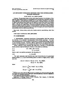
The method has been implemented and tested on reference geometries such as a cone and an elliptic paraboloid. Figure 3 below compares the shape of the wetted surfaces obtained for several values of Nha with the analytical solution derived by [1] for an elliptic paraboloid. It can be seen that a good approximation of the intersection line is achieved with Nha=5. The proposed solution method for the 3D Wagner problem makes it possible to compute the hydrodynamic pressure acting on a 3D body using the Modified Logvinovich Model (MLM) [6] and then to compute the hydrodynamic force F by integrating the pressure. Figure 4 below depicts the slamming coefficient CS ( CS = 2 F /( ρV 2 ) ) during the water impact at constant
speed of an elliptic paraboloid ( f ( x, y ) ≈ 1.418 x 2 + 0.517 y 2 ). The MLM results are compared to Finite Element results performed by ABAQUS/Explicit using the VOF method and experimental data carried out using a hydraulic shock machine at a constant speed V of 12m/s (see [7] for more details on the experimental set-up). Results are in very good agreement until the total immersion of the mock-up is reached ( d (t ) ≈ 0.023 ). Oscillations can be observed on the experimental data because of impact induced vibrations of the mock-up. 1
0.8
Analytic Nha=1 Nha=3 Nha=5
0
0.6 Cs
x
0.1
0.4
Experiment Abaqus 3D Wagner
-0.1 0.2
-0.2 -0.15 -0.1 -0.05
0 y
0.05
0.1
0.15
0.2
Figure 3: Intersection line for an elliptic paraboloid.
6
0 0
0.005
0.01 0.015 0.02 Penetration Depth (m)
0.025
0.03
Figure 4: Slamming coefficient as a function of the penetration depth.
CONCLUSION
A fast numerical method for three-dimensional water impact problems is proposed. This method is based on the Wagner approach and the displacement potential formulation. With the proposed approach, the solution at a particular instant of time is independent of the previous instants of time. As a result, it can be computed very quickly. Moreover, the accuracy of the solution remains constant as the time increases. The prediction of the wetted surface has been first validated by analytical results for an elliptic paraboloid. Then, the prediction of the slamming force has been shown to be in good agreement with numerical and experimental reference results. Other comparative studies have been carried out on several three-dimensional geometries. The proposed method was shown to be very promising. Further work will consist in coupling the fluid model to structural calculations. Then, industrial applications will be considered.
REFERENCES [1] Scolan Y.-M., Korobkin A., “Three-dimensional theory of water impact. Part1: Inverse Wagner problem”, Journal of Fluid Mechanics, Vol. 440, (2001) [2] Schellin T., el Moctar O., “Numerical prediction of impact-related wave loads on ships”, Journal of Offshore Mechanics and Arctic Engineering, Vol. 129, p. 39-47, (2007) [3] Tassin A., Jacques N., Nême A., Laurens J.-M., “Simplified models for the estimation of slamming loads on bulbous bows”, In proceedings of the 11th Numerical Towing Tank Symposium, Brest, (2008) [4] Küttler U., Wall W.A., “Fixed-point fluid-structure interaction solvers with dynamic relaxation”, Computational Mechanics, 72, 43:61, (2008) [5] Bonnet M., Boundary integral equations for solids and fluids, 412 p., John Wiley & Sons, (1999) [6] Korobkin A., “Analytical models of water impact”, European Journal of Applied Mathematics, Vol.16, p. 1-18, (2005) [7] Constantinescu A., El Malki Alaoui A., Nême A., Rigo P., “Numerical and Experimental studies of simple geometries in slamming”, Proceeding of the 19th International Offshore and Polar Engineering Conference, Osaka, (2009)