An Efficient Source-and-Receiver-Directional RIR Measurement Method Markus Zaunschirm, Christoph Baumgartner, Christian Sch¨orkhuber, Matthias Frank, Franz Zotter Institute of Electronic Music and Acoustics, University of Music and Performing Arts, 8010 Graz, Austria. Email:
[email protected]
Introduction Typically, the point-to-point room impulse response (RIR) is measured using a source and a receiver with an omnidirectional directivity. However, since natural sources do not radiate sound uniformly in all directions and listeners do not perceive sound direction independently, but weighted by their head related transfer functions, a new measurement method is needed in order to deliver an RIR flexible to arbitrary source and receiver directivities. Similar to the spatial decomposition method (SDM [1]), we assume both temporal and directional sparseness, which is most likely true for the important early RIR parts. This assumption allows us to sharply assign each time sample of the point-to-point omnidirectional RIR to a specific direction at both sides, yielding a source-andreceiver-directional (SRD) RIR. We propose an efficient SRD RIR measurement method using inexpensive compact spherical arrays to measure the MIMO-RIR between a cubic six-channel source and a tetrahedral four-channel receiver. Both sides are processed utilizing a direction of arrival (DOA) estimation. We present measurements in a lecture room as a proof of concept for measurementbased real-time auralization, and a listening experiment to evaluate the proposed SRD RIR processing.
and source directivity, respectively. By inserting Eq. (2) and Eq. R(3) into Eq. (1), and with the orthogonality 0 mm0 property S2 Ynm (θ)Ynm0 ∗ (θ)dθ = δnn 0 , the resulting RIR is expressed as h(t) =
0
NR X
NS X n n X X
0
0
S γnR0 m0 hnnmm (t)γnm .
(4)
n0 =0 m0 =−n0 n=0 m=−n
Sparse SRD RIR: In its early part, we assume the SRD RIR to be temporally and directionally sparse and composed of discrete sound propagation paths [2]. Each path is characterized by a sharp receiving and emitting ri S direction, θR i , θi , a sharp arrival time τi = c , its length ri , and amplitude ai , yielding a sparse SRD RIR, which, e.g. results from ray tracing or image source room models, h (θR , t, θS ) =
X ai δ(θR −θR )δ(t−τi )δ(θS −θS ) i
i
ri
i
. (5)
In the SH-domain, Eq. (5) is expressed by a multiplication of each time sample with the SH evaluated at the directionof-arrival (DOA) for both source and receiver, 0 0 hnnmm (t)
=
X ai Y m0 0 (θR )δ(t − τi )Y m (θS ) n
i
n
i
ri
i
.
(6)
Concept of a SRD RIR
Efficient SRD RIR Measurement
For a specific source and receiver directivity, gS (θS ) and gR (θR ), the corresponding RIR h(t) can be defined based on a generic SRD RIR h (θR , t, θS ) by integrating over the radiation and pickup ray directions θS and θR Z Z h(t) = gR (θR )h (θR , t, θS ) gS (θS ) dθR dθS , (1)
The conceptual block diagram of an efficient SRD RIR measurement method is depicted in Fig. 1.
S2
where all θ = [cos(ϕ) sin(ϑ), sin(ϕ) sin(ϑ), cos(ϑ)] are unit direction vectors, (ϕ, ϑ) are the azimuth and zenith angles, and the labels S, R refer to source or receiver. For time-variant directivity changes and real-time auralization, we require a less generic formulation in order to make use of the SRD RIR. The SRD RIR as well as the directivities gA (θA ), A = {S, R} can be represented by expansion of Spherical Harmonics (SH) Ynm (θ) of order n and degree m X X 0 0 0 h (θR , t, θS ) = Ynm0 (θR ) hnnmm (t) Ynm (θS ), (2) n0 ,m0 n,m
gA (θA ) =
NA X n X
A γnm Ynm (θA ),
(3)
n=0 m=−n 0
where hnnmm (t) is the SH-domain SRD RIR, and NR and NS are the maximum orders used to represent the receiver
6×4
DOA estimation at source and receiver array using PIV at receiver using TMSR at source
S2 T
0
Measuring of MIMO RIR
6×4
6×4
Omni to Omni RIR summing over channels
1
Denoising in third-octave bands
ΘR ΘS
1
Combination of DOAs and Omni to Omni RIR SRD RIR h(ΘS , t, ΘR )
Figure 1: Block diagram of an efficient SRD RIR measurement method.
The MIMO-RIRs between a 6-channel compact spherical loudspeaker array with a radius of 7.5 cm and a 4-channel B-format microphone array (see Fig. 4) are measured in the IEM lecture room (6.8 m×7.6 m× 3.1 m) using the exponentially-swept sine technique. The room layout and array positioning is depicted in Fig. 2. Depending on the array geometry, an approximation of the point-to-point omnidirectional RIR can be obtained from the MIMO RIR by transforming both sides in the SH-domain and taking the response between the 0th order components. If the array elements are arranged according to a spherical t-design, the approximated omnidirectional impulse response h0 (t) is calculated by summing over all channels.
(a) Original.
(b) Denoised.
Figure 4: Spectrograms of the approximated point-to-point omnidirectional room impulse response h0 (t) before and after denoising in third-octave bands.
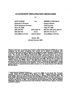
Figure 2: Layout of IEM lecture room and positioning of source and receiver array. Source position is [5.2×2.6×1.4] m and receiver position is [1×3.2×1.4] m.
As the ST450 spherical microphone array outputs Bformat signals we suggest using the simple pseudointensity-vector (PIV) approach in a frequency range between 200 Hz and 3 kHz (below spatial aliasing) for DOA estimation at the receiver [5]. For DOA estimation at the source we use an approach that is based on the transformed magnitude sensor response (TMSR) [3]. Figure 5 shows the estimated as well as the expected DOAs for the first 18 ms of the RIR. 0°
0°
(b) TSL ST450.
18
90°
(a) Cubelet.
estimated DOA expected DOA
90°
estimated DOA expected DOA
18
m
s
Figure 3: Compact arrays that are used to measure the MIMO-RIRs. (a) Spherical 6-channel loudspeaker array prototype with loudspeakers arranged on surfaces of a cube and (b) 4-channel Ambisonic B-format microphone array.
Ideally, the direct path in h0 (t) is modeled as a single impulse. However, due to the non-ideal responses of the loudspeakers and microphones as well as the array geometries (radius of 7.5 cm and 2 cm at source and receiver, respectively), even the direct path will be spread in time. A possible approach for improving the omnidirectional response is outlined in [3]. Denoising Despite using relatively long sweeps (3 s), we experienced unrealistic and long reverberation times in the RIR (especially at high frequencies) that can be explained by the limited efficiency of the loudspeakers (Fountek FR58EX, 2 inch coil diameter with ±3 mm maximum linear excursion). Thus, exponentially decaying envelopes are applied to noisy parts of the third-octave decomposed RIR h0 (t), as described in [4]. The spectrograms of the original and the denoised response h0 (t) are depicted in Fig. 4. Direction of Arrival Estimation For each discrete time step, a DOA estimator gives the average direction of the array signals in a centered small time window of length W = 32. Please note that any DOA estimator (SRP, MUSIC, etc.) can be used, based on the chosen source and receiver array.
12
m
s
6
m
s
6
m
s
0
m
s
12 m
s
0
m
s
m
s
(a) Source.
(b) Receiver.
Figure 5: DOA estimation (azimuth) at the source and receiver for the first 18 ms of the RIR. The energy of the RIR is encoded in the size and color of the dots (bigger, darker dots correspond to higher energy). The expected DOAs (marked by crosses) are calculated for a simple shoebox room using image sources up to first order.
Directional Sharpening and Spectral Correction In accordance to Eq. (6), and assuming a single reflection path at a time (disjointness), the resolution-enhanced SHdomain SRD RIR uses the time-variant DOA estimations θR (t), θS (t) and becomes 0
0
0
hnnmm (t) = Ynm0 [θR (t)] h0 (t) Ynm [θS (t)] .
(7)
Here, multiplication of the omnidirectional RIR h0 (t) by the representations of δ [θR − θR (t)] and δ [θS − θS (t)] in the SH-domain directionally sharpens the SRD RIR. This multiplication, however, introduces an amplitude modulation to h0 (t), which increases with n,n0 , and thus, yields spectral whitening towards high orders. DueP to the property of the spherical harmonics n 4π m=−n |Ynm (θ)|2 = 2n + 1 in each order n, the orderdependent spectral whitening incurred by directional
Source directivity in spherical harmonics domain
Ambisonics playback
room database (SRD)
◦
(184 , 90 )
signal x
Ambi. Encoder
(NS +1)2
(NS+1)2 × (NR+1)2
Headphones
Expansion coeffs
(NR+1)2
Binaural Decoder
(NS+1)2
SRD RIR in spherical domain harmonics ′ m hm n′ n (t)
2
(NR+1)2
33000 samples
Loudspeakers
Beam 2
angles ◦
(NS +1)2
Ambisonic Decoder
signal x
Ambi. Encoder
Ambisonics Bus
Beam 1 angles
(0◦, 90◦ )
Ambisonic Rotation
ϕhead , ϑhead
NLs
Figure 6: Block diagram of measurement-based auralization using the SRD RIR in the SH-domain.
sharpening is energy-preserving for every n, n0 ,
uth 0° azim
3
0
1
45 °
n X
0
nm |hnm (t)|2 = (2n0 + 1)(2n + 1) h20 (t), (8)
2
5° -4
0
n X
m=−n m0 =−n0
8
0
6
9
elevation
0°
20° 40° 60°
12
10
11 5
5°
13
4
-1 3
5°
7
90°
-90°
90°
0
where hnnmm (t) is defined according to Eq. (7). We therefore shift the spectrally whitened third-octave energy decay back to the energy decay of the original h0 (t) within each n, n0 block of the higher-order SRD RIR components. The correction within these blocks instead of correcting the overall spectral SRD RIR energy is relevant: It ensures that the room response exhibits consistent spectrum and decay when varying the directivity order.
-180°
Auralization with Sharpened SRD RIR While the SRD RIR can be used to calculate the RIR for a desired source and receiver directivity, see Eq. (1), or to analyse the reflectogram, we want to present its applicability for measurement-based real-time auralization of sources with arbitrary directivity. The block diagram of the suggested approach is depicted in Fig. 6. As outlined in the processing chain, the directional source signals, which are represented in the SHdomain, are convolved with the directionally sharpened SRD RIR matrix. Note that the SRD RIR sharpening should be done (i) up to at least the directivity order of the source, and also (ii) up to the order of the receiving directivity to which it should model the room transfer function. The signals obtained through real-time convolution1 of the source signal with the sharpened SRD RIR matrix are either decoded for loudspeaker playback or dynamic binaural rendering. Listening Experiments We know from [6] and [7] that sources with controllable directivity can be used to create various distance impressions of an auditory object by implicitly controlling the direct-to-reverberant energy ratio (D/R ratio). One way of creating such D/R ratio changes using the SRD RIR is the crossfading of source directivities that (i) point to the listener and (ii) away from the listener. The panning ratio between the directivities is listed in Tab. 1, where −∞|∞ 1 Using
the mcfx VST plug-in for partitioned convolution, http://www.matthiaskronlachner.com/
Figure 7: Loudspeaker setup in the IEM production studio. The loudspeakers on the lowest ring are arranged according to the ITU-R BS.2159 7.1 recommendations.
indicate that only the directivity away from and towards the listener is present, respectively. In the presented listening experiment we tested if previous results [6] can be reproduced with measurement-based auralization using the proposed SRD RIR processing. The experiment was conducted in the IEM production studio using 12 loudspeakers for playback. The arrangement of loudspeakers is depicted in Fig. 7 and the corresponding Ambisonics decoder is calculated according to [8]. The listening experiment consisted of 5 test trials. In trials 1−4 we tested all conditions listed in Tab. 1 for four different combinations of source and receiver directivity orders NS |NR . In the 5th trial we tested conditions 1 and 7 for all source and receiver directivity combinations, which allowed us to scale the results from trials 1 − 4 accordingly. Note that both the order of trials and the order of stimuli in each trial were randomized. We asked 15 experienced listeners to rate the perceived distance on a continuous scale from near to far in a MUSHRA-like test environment. Table 1: Panning ratios for tested crossfading conditions of directivities.
condition ratio [dB]
1 −∞
2 −12
3 −6
4 0
5 6
6 12
7 ∞
Participants finished the experiment in approximately 12 minutes. The median and 95% confidence interval of all ratings are depicted in Fig. 8. It can be seen that perceived distance differences are more pronounced and graduated as the source directivity increases. The receiver order had little effect on the distance impression, which was expected, as the receiver order does not influence the D/R ratio. However, verbal feedback of test participants suggests that the robustness of the acoustic scene to head movements and translation of listeners increases with higher receiver order. Furthermore, listeners reported a natural sounding acoustic scene and no artefacts were audible. In order to further validate the applicability of SRD RIRs for measurement-based auralization, tests using data from physical sources (e.g. icosahedral loudspeaker array, IKO) and tests examining the perceived directions, similar to the experiments in [4], are needed. Far
Middle
1|1 1|5 5|1 5|5
Near
1 2 3 4 5 6 7 1 2 3 4 5 6 7 1 2 3 4 5 6 7 1 2 3 4 5 6 7
condition
Figure 8: Listening test results showing the median and 95% confidence interval of overall 15 ratings from experienced listeners. The SH orders used represent the source and receiver directivity are indicated in the legend as NS |NR .
Conclusion We introduced the concept of source-and-receiverdirectional room impulse responses (SRD RIR), which allows us to auralize the room responses to sources and receivers of arbitrary directivity, based on measurements with low hardware and time effort. For a correct auralization, the resolution of the SRD RIR needs to be high enough for both the source and receiver directivity. Typically, the attempt to accomplish this yields measurement procedures with high effort [9, 10]. To achieve simplification, our solution uses inexpensive compact spherical measurement arrays instead, and by assuming directional and temporal sparseness, we can successfully sharpen the directional resolution by an SDMlike [1] approach. The processing involves denoising of the approximated point-to-point omnidirectional RIR, an assignment of an emitting and a receiving direction to each of its time samples, a directional sharpening, and a third-octave timbre correction of higher order components of the resulting SRD RIR in the SH-domain.
Although the assumption of temporal and spatial sparseness is not valid in the later part of the SRD RIR, results from our listening experiments indicate that the presented approach can be used for measurement-based real-time auralization of sources with arbitrary directivity. The experiment moreover indicates that the spatial fidelity is highest when more directional sharpening is employed for both the source and receiver side of the SRD RIR.
Acknowledgements This work is part of the project Orchestrating Space by Icosahedral Loudspeaker (OSIL), which is funded by the Austrian Science Fund (FWF): PEEK AR 328. We thank all listeners for their participation in the experiments.
References [1] S. Tervo, J. P¨atynen, A. Kuusinen, and T. Lokki, “Spatial decomposition method for room impulse responses,” Journal of the Audio Engineering Society, vol. 61, no. 1/2, pp. 17–28, 2013. [2] H. Morgenstern, F. Zotter, and B. Rafaely, “Joint spherical beam forming for directional analysis of reflections in rooms,” The Journal of the Acoustical Society of America, vol. 131, apr 2012. [3] C. Schoerkhuber and R. Hoeldrich, “SignalDependent Encoding for First-Order Ambisonic Microphones,” Fortschritte der Akustik, DAGA, Kiel, 2017. [4] M. Zaunschirm, M. Frank, and F. Zotter, “An Interactive Virtual Icosahedral Loudspeaker Array The ICO The virtual ICO,” Proc. DAGA, 2016. [5] D. P. Jarrett, E. A. P. Habets, and P. A. Naylor, “3D Source localization in the spherical harmonic domain using a pseudointensity vector,” European Signal Processing Conference, 2010. [6] F. Wendt, M. Frank, F. Zotter, and R. H¨oldrich, “Directivity patterns controlling the auditory source distance,” DAFx (accepted), pp. 295–300, 2016. [7] M.-V. Laitinen, A. Politis, I. Huhtakallio, and V. Pulkki, “Controlling the perceived distance of an auditory object by manipulation of loudspeaker directivity,” The Journal of the Acoustical Society of America, vol. 137, no. 6, pp. EL462–EL468, 2015. [8] M. Romanov, M. Frank, F. Zotter, and T. Nixon, “Manipulations improving amplitude panning on small standard loudspeaker arrangements for surround with height,” 29th Tonmeistertagung - VDT International Conference, 2016. [9] B. Bernsch¨ utz, C. P¨orschmann, S. Spors, and S. Weinzierl, “Entwurf und Aufbau eines variablen sph¨ arischen Mikrofonarrays f¨ ur Forschungsanwendungen in Raumakustik und Virtual Audio,” Forschschritte der Akustik - DAGA 2010, pp. 717– 718, 2010. [10] J. Klein, M. Pollow, and M. Vorlaender, “Optimzed Spherical Sound Source for Auralization with arbitrary directivity,” in Proc. of the EAA Joint Symposium on Auralization and Ambisonics, 2014.