Mar 3, 1999 - the warping algorithm of Sect. 4.1. 3. DP Algorithm for Optimal 2DW. The 2DW problem can be treated as the optimal state transition sequence ...
IEICE TRANS. INF. & SYST., VOL.E82–D, NO.3 MARCH 1999
693
PAPER
An Efficient Two-Dimensional Warping Algorithm∗ Seiichi UCHIDA† , Student Member and Hiroaki SAKOE† , Member
SUMMARY A new dynamic programming (DP) based algorithm for monotonic and continuous two-dimensional warping (2DW) is presented. This algorithm searches for the optimal pixel-to-pixel mapping between a pair of images subject to monotonicity and continuity constraints with by far less time complexity than the algorithm previously reported by the authors. This complexity reduction results from a refinement of the multi-stage decision process representing the 2DW problem. As an implementation technique, a polynomial order approximation algorithm incorporated with beam search is also presented. Theoretical and experimental comparisons show that the present approximation algorithm yields better performance than the previous approximation algorithm. key words: two-dimensional warping, image matching, dynamic programming, correspondence optimization, Markovian process formulation
1.
Introduction
Two-dimensional warping (2DW), a pixel-to-pixel mapping technique between a pair of images is one of the most challenging problems in the pattern recognition area. Many researchers have been attracted by 2DW from their purely theoretical interests and/or their expectations for its wide prospective applicability to real problems. Several 2DW methods based on dynamic programming (DP) have been proposed [1]–[5] motivated by successful applications of DP to the time warping problem in speech recognition [6]–[8]. Among them, the method proposed by Levin and Pieraccini [1] is the most promising one, we considered. Their algorithm searches for the optimal monotonic pixel-topixel mapping with minimum residual error. For practical use, however, there remained two serious problems, i.e., excessive deformation and prohibitive computational complexity. Starting from their method, the authors have developed a monotonic and continuous 2DW [9]. The warp given by the method preserves topological structure in images, thus suppressing certain parts of the excessive deformation. The computational complexity of the algorithm was significantly reduced by the continuity constraint ; nevertheless, it remained at exponential Manuscript received August 5, 1998. The authors are with the Graduate School of Information Science and Electrical Engineering, Kyushu University, Fukuoka-shi, 812–8581 Japan. ∗ This work was supported in part by the Ministry of Education, Science, Sports and Culture in Japan under a Grant-in-Aid for Scientific Research C(2) (No.10680385). †
order of image size N . In this paper, a more efficient DP-based algorithm for the monotonic and continuous 2DW is presented. The DP algorithm provides the same warping result as the previously reported algorithm [9], with by far less computations. In the following, the warping problem we discuss is first formalized. The warping process is modeled as a sequential optimization process, or multistage decision process, along the raster scanning path, where it is pointed out that this process belongs to N th-order Markovian decision process. Second, the DP algorithm is described which searchs for the optimal decision sequence. The entire optimal decision sequence gives the optimal monotonic and continuous 2DW between given two images. Third, a polynomial order approximation algorithm for the 2DW is presented, where beam search technique is incorporated for pruning off less hopeful search paths at each DP stage. Finally, it is shown that these algorithms have higher computational efficiency than their previous versions reported in [9]. 2.
Problem Formulation
The monotonic and continuous 2DW problem is formulated as a restricted pixel-to-pixel correspondence optimization problem. Consider two images A = {a(i, j) | i, j = 1, . . . , N } and B = {b(x, y) | x, y = 1, . . . , M }. The optimal 2DW between A and B is defined by the warping function x(i, j), y(i, j) which minimizes the following criterion function N � N �
|a(i, j) − b(x(i, j), y(i, j))| ,
(1)
i=1 j=1
subject to monotonicity and continuity constraints defined as 0 ≤ y(i, j) − y(i, j − 1) ≤ 2,
(2)
|x(i, j) − x(i, j − 1)| ≤ 1,
(3)
0 ≤ x(i, j) − x(i − 1, j) ≤ 2,
(4)
|y(i, j) − y(i − 1, j)| ≤ 1.
(5)
Vertical and horizontal monotonicity and continuity relations between a pixel and its 4-adjacent pixels are
IEICE TRANS. INF. & SYST., VOL.E82–D, NO.3 MARCH 1999
694
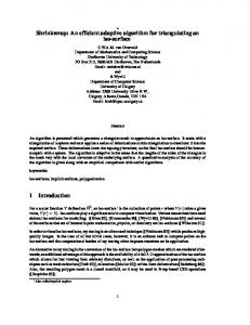
Fig. 1 Examples of monotonic and continuous 2DW. (N = M = 32.)
preserved by these constraints. Thus, the topological structure in images is approximately preserved through warping. In addition, boundary conditions x(1, j) = y(i, 1) = 1,
(6)
x(N, j) = y(i, N ) = M
(7)
are applied. Let D(A, B) denote the minimum of the criterion function (1), i.e., D(A, B) = min
N � N �
|a(i, j) − b(x(i, j), y(i, j))| .
(8)
i=1 j=1
The quantity D(A, B) gives a distance between A and optimally deformed B, and can be interpreted as the residual error between A and B yielded by the warping. From the viewpoint of structural analysis, the optimal warping function x(i, j), y(i, j) gives an interpretation of the image A according to the generation model B. Figure 1 shows examples of the 2DW obtained by the warping algorithm of Sect. 4.1. 3.
DP Algorithm for Optimal 2DW
The 2DW problem can be treated as the optimal state transition sequence decision problem on a multi-stage decision process. In this section, we introduce a new decision process for the 2DW, shown in Fig. 2, and give its detailed specifications ; stage, state, state transition and transition cost according to Bellman’s terminology [10]. A DP algorithm searching for the optimal decision sequence is then described. 3.1 Stage Stages are arranged along the vertical raster scanning path (1, N ), (2, 1), . . . , (i − 1, N ), (i, 1), . . . , (i, j), . . . , (i, N ), (i + 1, 1), . . . , (N, N ).
At each stage (i, j), the mapping of the pixel (i, j), i.e., (x(i, j), y(i, j)) is decided. These decisions are mutually constrained by (2) – (5). Figure 3 schematically explains these constraints. By (2) and (3), the decision (x(i, j), y(i, j)) is limited to the 3 × 3 hatched square (a) with relation to (x(i, j −1), y(i, j −1)). The decision is also limited, by (4) and (5), to another 3 × 3 hatched square (b) with relation to (x(i − 1, j), y(i − 1, j)). The intersection of these two squares gives the possible range for the decision (x(i, j), y(i, j)). Thus, the decision at stage (i, j) is constrained by the directly preceding decision as well as by the N stage preceding decision. This means that the decision process considered here is an N th-order Markovian decision process. For dealing with this N th-order Markovian nature, it is convenient to consider that each stage (i, j) is accompanied by the wake [(i − 1, j + 1), . . . , (i − 1, N ), (i, 1), . . . , (i, j)]. The left part of Fig. 4 shows the wakes of stages (i, j − 1) and (i, j). Note that at initial stage (1, N ) the mapping of the pixels (1, 1), . . . , (1, N ) is decided. The mapping is not limited by (4) nor (5), while it is strictly limited by the boundary condition (6). 3.2 State (Warped Wake) A state in stage (i, j) is a mapping of the wake of stage (i, j). This mapping is called warped wake and denoted as xy(i, j) (often abbreviated as xy), i.e., xy(i, j) = [(x(i − 1, j + 1), y(i − 1, j + 1)), . . . , (x(i − 1, N ), y(i − 1, N )), (x(i, 1), y(i, 1)), . . . , (x(i, j), y(i, j))]. (9) The right part of Fig. 4 shows an example of warped wake xy(i, j). The monotonicity and continuity constraints (2) and (3) hold in the individual warped wakes, while the other constraints (4) and (5) hold between consecutive warped wakes xy(i, j − 1) and xy(i, j) as is discussed in the next part. The boundary conditions (6) and (7) also hold in each warped wake. Let XY (i, j) denote the set of such warped wakes, or states, at stage (i, j). 3.3 State Transition A state transition sequence, i.e., a decision sequence, from stage (1, N ) to (N, N ) corresponds to an entire warp from the image A onto the image B. For notational simplicity, we denote warped wakes xy ∈ XY (i, j) and xy ∈ XY (i, j − 1) as xy = [(x1 , y1 ), . . . , (xk , yk ), . . . , (xN , yN )] , xy = [(x1 , y1 ), . . . , (xk , y k ), . . . , (xN , yN )] .
(10) (11)
The readers are expected to be careful with the twofold notations for a warped wake xy, i.e., (9) and (10). If the following conditions are satisfied, the transition from
UCHIDA and SAKOE: AN EFFICIENT TWO-DIMENSIONAL WARPING ALGORITHM
695
Fig. 2
The multi-stage decision process of the proposed algorithm.
Fig. 3
Fig. 4
N th-order Markovian nature of the 2DW problem.
Wakes and warped wakes standing for consecutive states.
IEICE TRANS. INF. & SYST., VOL.E82–D, NO.3 MARCH 1999
696
1 2
/* Initialization */ for all xy ∈ XY (1, N ) do �N g(1, N, xy) := k=1 |a(1, k) − b(xk , yk )|
3 4 5
/* Recursion */ for i := 2 to N do begin for all xy ∈ XY (i, 1) do /* j = 1 */ g(i, 1, xy) := d(i, 1, xy) + min g(i − 1, N, xy)
xy ∈ XY (i, j). Step 5 and 8 are so-called DP-equation. While back pointer and backtracking operations to obtain the optimal warp are omitted from the algorithm description, the readers can easily provide these operations. 3.6 Computational Complexity Here, we discuss the time and space complexity of the above DP algorithm for the case of N = M . The time complexity is proportional to the total number of possible state transitions in the entire decision process of Fig. 2. This is given by the product of the numbers of stages (wakes), states (warped wakes) belonging to each stage, and possible transitions from each state. From the foregoing discussion, it is clear that the number of stages is N (N − 1), i.e., O(N 2 ), and the number of possible transitions from each state is at most 9, i.e., O(1). As is shown in Appendix, the number of states belonging to each stage is O(N 9N ). Thus the time complexity becomes O(N 3 9N ). The space complexity is proportional to the total number of states, and therefore it becomes O(N 3 9N ) (or O(N 9N ) when backtracking is not necessary).
xy∈XY(xy)
6 7 8
for j := 2 to N do /* j > 1 */ for all xy ∈ XY (i, j) do g(i, j, xy) := d(i, j, xy) + min g(i, j − 1, xy) xy∈XY(xy)
9
10
end /* Termination */ D(A, B) := min
xy∈XY(N,N )
Fig. 5
g(N, N, xy)
DP algorithm for the optimal 2DW.
state xy to xy is allowed. Monotonicity and continuity (from (4) and (5)): (12) 0 ≤ xN − x1 ≤ 2, |yN − y 1 | ≤ 1. Transition consistency: xk = xk−1 , y k = yk−1 2 ≤ k ≤ N. (13) The right part of Fig. 4 shows an example of warped wakes xy and xy satisfying the above conditions. Let XY (xy) denote the set of the preceding states xy of xy. Note that the size |XY (xy)| does not increase with the image size N nor M , and is at most 9. This comes from the fact that the intersection of the two hatched squares in Fig. 3 contains maximally 9 pixels. 3.4 Transition Cost As is discussed in Sect. 3.1, the mapping (x(i, j), y(i, j)) is decided at stage (i, j). Therefore, by considering the criterion function (1), the following cost is additively imposed to the transitions to the state xy ∈ XY (i, j) d(i, j, xy) = |a(i, j) − b(xN , yN )| or = |a(i, j) − b(x(i, j), y(i, j))|.
(14)
3.5 DP Algorithm Now the 2DW problem can be solved by searching all possible state transition sequences in the above decision process for one with minimum cumulative cost. This search can be efficiently performed by DP. Figure 5 depicts the DP algorithm, where g(i, j, xy) denotes the cumulative cost along the optimal state transition sequence from a certain initial state xy(1, N ) to the state
4.
Approximation Algorithm
4.1 Applying Beam Search to DP Process In this section, a polynomial order approximation algorithm incorporated with beam search technique is presented. In this algorithm, only first R states with the smallest cumulative costs are taken into account as the active search paths for optimal state, and the remainder is pruned off, at each stage. The number R is called beam size. Procedure at stage (i, j) is depicted in Fig. 6. In the algorithm, dynamic list technique [11], [12] is employed so that the beam search can most effectively work. The list LISTi,j−1 consists of items �g, xy , where xy ∈ XY (i, j − 1) and g is the cumulative cost up to the state xy. (For notational simplicity, we omit the back pointer from this item description.) The list Sx,y , sublist in LISTi,j , consists of items �g, xy where xy ∈ XY (i, j) and its last element (xN , yN ) = (x, y), and g is the cumulative cost up to xy. Regarding the element (xk , yk ) in Eq. (11) as M ary two-digit number, an xy stands for an M -ary 2N digit number. As is discussed in the next section, once items in LIST1,N are sorted in ascending order with regard to this numeric expression, items in LISTi,j automatically continue to hold the same ordering relation up to the final stage (N, N ). The DP-equation is calculated on these lists through the following two simple operations. 1) Create items �g, xy from an item �g, xy in the LISTi,j−1 , when g is smaller than the pruning
UCHIDA and SAKOE: AN EFFICIENT TWO-DIMENSIONAL WARPING ALGORITHM
697
1
/* Deciding pruning threshold */ θ := Rth smallest cost g in LISTi,j−1
2
/* Reset Sx,y */ for all x, y do ux,y := 0
3 4
/* Scanning LISTi,j−1 */ for t := 1 to |LISTi,j−1 | do begin �g, xy := LISTi,j−1 (t)
5
/* Pruning */ if g > θ then continue
6 7 8
/* Creating items */ for all xy which satisfies xy ∈ XY (xy) do begin g := g + d(i, j, xy)
9 10 11 12 13 14 15 16 17 18 19 20
/* Appending the created item to Si,j */ if uxN ,yN = 0 then �g � , xy � := SxN ,yN (uxN ,yN ) else xy � := null if xy = xy� then /* Selection */ if g < g � then SxN ,yN (uxN ,yN ) := �g, xy else begin /* Appending */ uxN ,yN := uxN ,yN + 1 SxN ,yN (uxN ,yN ) := �g, xy end end end
21
/* Make LISTi,j by concatenating Si,j */ LISTi,j := {S1,1 , . . . , Sx,y−1 , Sx,y , . . . , SM,M }
Fig. 6 (i, j).
Procedure of the approximation algorithm at stage
Fig. 7
Beam search with dynamic list technique.
threshold θ. Here, xy is a successor of xy, i.e., xy ∈ XY (xy). (Step 3-8 of Fig. 6.) 2) Append the created item �g, xy after �g � , xy� , the latest item of SxN ,yN , if xy = xy � . Otherwise, i.e., if xy = xy � , the smaller of the costs g and g � is given to the item. (Step 9-18 of Fig. 6.) Figure 7 illustrates these operations. Let cumulative cost g in item (a) be smaller than the threshold θ, then new items (b),(c),. . .,(d) are created by the operation 1). As is indicated by hatching, [(x2 , y 2 ), . . . , (xN , yN )] in (a) is transferred to (b),(c),. . .,(d) to form [(x1 , y1 ), . . . , (xN −1 , yN −1 )] in the new warped wakes xy. By the operation 2), when the created item has the same warped wake as an existing item, (c) for example, only the cumulative cost g in the item is updated. 4.2 Computational Complexity of Approximation Algorithm The space complexity of the present approximation algorithm is polynomial and therefore by far less than O(N 3 9N ) of the Fig. 5 DP algorithm for the optimal 2DW. This is because LISTi,j (i.e., Sx,y ) is dynamically allocated in the course of the above discussed operations. These operations create maximally 9R new items in LISTi,j , since |XY (xy)| ≤ 9 for each xy. Thus, the size of LISTi,j is O(N R) and the space complexity of the algorithm is O(N 3 R) (or O(N R) when backtracking is not necessary). From the viewpoint of the time complexity, there are two advantages of the present approximation algorithm. The first advantage comes from the data-driven organization of the algorithm. In stage (i, j), the maximally 9R items in LISTi,j−1 are scanned for the pruning test and R items in them are used for driving DP operations 1) and 2). Thus, by this data-driven organization, LISTi,j is made up without the exhaustive scan of XY (i, j), and therefore overhead of the algorithm is effectively reduced. The second advantage is that the updating of the cost g in the operation 2), xy = xy � case, is easy to do. For doing this updating, the location of the previously listed item �g, xy has to be identified in S1,1 , . . . , SM,M . Conveniently, this item is the latest item in the sublist SxN ,yN where (xN , yN ) is the last element of xy. Thus the item in demand can be directly accessed without searching throughout entire S1,1 , . . . , SM,M . This merit comes from the initially set and consistently held ordering in LISTi,j−1 . In LISTi,j−1 , the items �g, xy from which the item with a certain xy can be created are adjacent . This is because such items have the same warped wake except for (x1 , y1 ), i.e., their first two-digits of the M -ary numeric expression. Therefore, when an item with xy is newly created, the item with the same xy previously created
IEICE TRANS. INF. & SYST., VOL.E82–D, NO.3 MARCH 1999
698
is the latest item of SxN ,yN . From the above fact, the time complexity for processing each item in LISTi,j−1 is bounded by O(9N ) = O(N ), where its dominant factor is computations for transferring xy to xy. It should be noted that the ordering of items in the LISTi,j given by the concatenation of Sx,y , is automatically held and therefore the algorithm does not require any computational effort for the sorting. Consequently, the time complexity of the algorithm becomes O(N 3 R). 4.3 Improving Techniques From the limitation of computational power, the beam size R is often set to a relatively small number. This sometimes causes undesirable side effect of pruning, yielding a significant error. One solution to this problem is to control the range of deformation. In the case of N = M , the warp range limitation, |x(i, j) − i| ≤ w,
|y(i, j) − j| ≤ w
(15)
where w is a positive integer, is a simple technique to limit the range of deformation. Use of a penalty to control the transition xy → xy is another practical solution to the problem. For example, the following penalty can be additively imposed to the transition
Fig. 8 The multi-stage decision process of the previously reported algorithm [9]. The illustration is revised according to present notations.
P (i, j, xy, xy) = |xN − xN −1 | + |xN − x1 − 1| + |yN − yN −1 − 1| + |yN − y 1 |. (16) The cost of the transition xy → xy then becomes d(i, j, xy) + αP (i, j, xy, xy), where α is a positive constant for controlling penalty effect. Examples in Fig. 1 are obtained by the present approximation algorithm (R = 1000) with the penalty (α = 10) and the range limitation (w = 5). 5.
Comparison with Previous Algorithms
In [9], the authors have proposed another DP algorithm for the optimal 2DW and its approximation algorithm incorporated with beam search. This section discusses the relative superiority of the present algorithms over these previous algorithms from the viewpoint of computational efficiency and warping quality. 5.1 Comparison between Two DP Algorithms Figure 8 shows the principle of the previously reported DP algorithm [9] in the form of multi-stage decision process (cf. Fig. 2). There are N stages, (1, N ), . . . , (i − 1, N ), (i, N ), . . . , (N, N ), and each stage (i, N ) is accompanied by the column of A, [(i, 1), (i, 2), . . . , (i, N )]. The O(N 9N ) states (called local warps [9]) belonging to stage (i, N ) are the mappings of the column. The link
Fig. 9 Sub-transitions in the previously reported approximation algorithm [9].
from a local warp belonging to stage (i − 1, N ) to a local warp belonging to stage (i, N ) is a state transition. Maximally 9N transitions possibly take place from each of the O(N 9N ) states. Total complexity of the previous algorithm, therefore, amounts to O(N 2 92N ), by far higher than O(N 3 9N ) of the present algorithm. The readers can understand that these two algorithms are equivalent in the sense that either algorithm gives a strict solution for Eq. (8) minimization problem. Thus, the superiority of the present algorithm in efficiency over the previous algorithm is established. 5.2 Comparison between Two Approximation Algorithms In the implementation of the previous O(N 2 R2 ) ap-
UCHIDA and SAKOE: AN EFFICIENT TWO-DIMENSIONAL WARPING ALGORITHM
699
Fig. 10
Average normalized distance D(A, B)/N 2 .
Fig. 11
Average computation time.
(i, N ). During these sub-transitions, no merging of search paths takes place, to the contrary that search paths with the same warped wake xy are merged by DP operations in the present algorithm. This means that the beam in the previous algorithm contains redundant search paths, thus reducing the effective number of active search paths. In order to examine the influence of the redundancy, average normalized distances D(A, B)/N 2 were compared between the present and previous algorithms at the same beam size R. The experiment is performed on three image sizes, 8, 16, and 32. One hundred pairs of images created from pseudorandom uniformly distributed noise over [0, 1) were prepared for each image size. The solution improving techniques discussed in Sect. 4.3 were not employed. Figure 10 shows the result. It can be observed that the present algorithm, which has no redundancy in its search paths, yields higher warping accuracy (i.e., less D(A, B)/N 2 ) than the previous algorithm at the same beam size R. We can not conclude the present algorithm superiority in the time complexity through a direct comparison between O(N 3 R) and O(N 2 R2 ). In the following, however, it is experimentally shown that the present algorithm requires practically less computation time than the previous algorithm. Figure 11 shows the computation time on SUN Ultra-2 (SPECint 95: 12.3, SPECfp 95: 20.2). It is not meaningful to simply compare the computation time at the same beam size R using Fig. 11. This is because the two algorithms attain different warping accuracy even with the same R, as was previously discussed. The computation time should be compared at the same accuracy. Figure 12 shows the ratio of the computation time at the same accuracy D(A, B)/N 2 , obtained from Fig. 10 and Fig. 11. The ratio 0.5 for instance means that the present algorithm is doubly faster than the previous algorithm. The result shows that the higher the required warping accuracy is, the more effective the present algorithm becomes than the previous algorithm, and maximally 10 times speedup (i.e., the ratio of 0.1) is achieved. 6.
Fig. 12
Conclusion
Computation time ratio.
proximation algorithm [9], a special consideration was required. There are O(9N ) possible transitions from each of the R states gathered in the beam. Therefore, if the beam search operation is directly applied to the Fig. 8 DP process, the algorithm essentially remained in an exponential class. In [9], every state transition was decomposed into N pixel-to-pixel sub-transitions and then pruning operation was performed at every sub-transition (that is, O(N 2 ) times pruning operations were performed). Figure 9 shows the sub-transitions, embedded in the transition from stage (i − 1, N ) to
A new DP algorithm for a monotonic and continuous two-dimensional warping (2DW) was presented. The algorithm requires far less time complexity than the DP algorithm previously reported by the authors. The complexity reduction results from the refinement of the multi-stage decision process representing the 2DW problem. As an implementation technique, a new polynomial order approximation algorithm incorporated with beam search was investigated. Theoretical and experimental comparisons have shown that the present approximation algorithm yields higher warping accuracy and/or less computation time than the previously reported approximation algorithm. This supe-
IEICE TRANS. INF. & SYST., VOL.E82–D, NO.3 MARCH 1999
700
riority is also given by the refinement of the decision process. It should be noted that the present algorithm is the most fundamental framework for two-dimensional warping, in the sense that no specific constraint is used except for monotonicity and continuity. This means that the algorithm is quite general and retains wide possibilities for further enhancements, by incorporating problem-specific constraints coming from the nature of the images submitted to warp.
Fig. A· 1 Four quantities [Q0 , Q1 , Q2 , Q3 ] for counting the number of warped wake.
References [1] E. Levin and R. Pieraccini, “Dynamic planar warping for optical character recognition,” Proc. ICASSP, pp.III 149– 152, 1992. [2] R.K. Moore, “A dynamic programming algorithm for the distance between two finite areas,” IEEE Trans. Pattern Anal. Mach. Intell., vol.PAMI-1, no.1, pp.86–88, Jan. 1979. [3] E. Tanaka and Y. Kikuchi, “A metric between pictures,” Trans. IEICE, vol.J63-D, no.12, pp.1018–1025, Dec. 1980. [4] C.M. Wu, R.M. Owens, and M.J. Irwin, “Distortion processing in image matching problems,” Proc. ICASSP, pp.2181– 2184, 1990. [5] M. Sugimura, Y. Iiguni, and N. Adachi, “A 2-dimensional dynamic programming for image matching with Zernike moments,” Trans. IEICE, vol.J80-D-II, no.1, pp.101–108, Jan. 1997. [6] H. Sakoe and S. Chiba, “Dynamic programming algorithm optimization for spoken word recognition,” IEEE Trans. Acoust. Speech & Sig. Proc., vol.ASSP-26, no.1, pp.43–49, Feb. 1978. [7] H. Sakoe, “Two-level DP-matching — A dynamic programming-based pattern matching algorithm for connected word recognition,” IEEE Trans. Acoust. Speech & Sig. Proc., vol.ASSP-27, no.6, pp.588–595, Dec. 1979. [8] H. Sakoe, “A generalized two-level DP-matching algorithm for continuous speech recognition,” Trans. IEICE, vol.E65, no.11, pp.649–656, Nov. 1982. [9] S. Uchida and H. Sakoe, “Monotonic and continuous twodimensional warping based on dynamic programming,” Trans. IEICE, vol.J81-D-II, no.6, pp.1251–1258, June 1998. [10] R. Bellman, “Adaptive Control Processes,” Princeton University Press, New Jersey, 1961. [11] H. Sakoe, H. Fujii, K. Yoshida, and M. Watari, “A highspeed dp-matching algorithm based on frame synchronization, beam search and vector quantization,” Systems and Computers in Japan, vol.20, no.11, pp.33–45, Nov. 1989. [12] H. Ney, D. Mergel, A. Noll, and A. Paeseler, “Data driven search organization for continuous speech recognition,” IEEE Trans. Sig. Proc., vol.40, no.2, pp.272–281, Feb. 1992.
Appendix:
The Number of States
Here, the number of states (or warped wakes) belonging to a stage is evaluated for the case of N = M . For convenience, we evaluate it as the product of four numbers Q0 , Q1 , Q2 and Q3 , each of which stands for the number of possible shapes (or positions) of divided warped wake. (See Fig. A· 1.) The number Q0 is the number of possible positions of x(i, 1) which gives the origin of the warped wake with y(i, 1) = 1.
Clearly, Q0 equals to N . The numbers Q1 , Q2 , and Q3 are the numbers of possible shapes of the warped wake between (x(i, 1), y(i, 1)) and (x(i, j), y(i, j)), between (x(i, j), y(i, j)) and (x(i − 1, j + 1), y(i − 1, j + 1)), and between (x(i − 1, j + 1), y(i − 1, j + 1)) and (x(i−1, N ), y(i−1, N )), respectively. From monotonicity and continuity constraints (2) and (3), Q1 and Q3 are bounded by O(9i−1 ) and O(9N −i−1 ), respectively. The number Q2 equals to 25. This comes from the number of relative positions of (x(i − 1, j), y(i − 1, j)) and (x(i, j − 1), y(i, j − 1)) such that the two 3 × 3 hatched squares in Fig. 3 have an intersection. Thus, the number of states belonging to a stage (i, j), i.e., |XY (i, j)| is bounded by O(N · 9i−1 · 25 · 9N −i−1 ) = O(N 9N ).
Seiichi Uchida received B.E. and M.E. degrees from Kyushu University in 1990 and 1992, respectively. In 1992, he joined SECOM Co., Ltd., Tokyo, Japan where he worked on speech processing. Since 1996, he has been a D.E. candidate at Graduate School of Information Science and Electrical Engineering, Kyushu University. His research interests include pattern analysis and speech processing. He is a member of IEEE, IPSJ and ASJ.
Hiroaki Sakoe received the B.E. degree from Kyushu Institute of Technology in 1966, and the M.E. and D.E. degrees from Kyushu University in 1968 and 1987, respectively. In 1968, he joined NEC Corporation and engaged in speech recognition research. In 1989, he left NEC Corporation to become a Professor of Kyushu University. His research interests include speech recognition and pictorial pattern analysis. He received 1979 IEEE ASSP Senior Award, 1980 IEICE Achievement Award and 1983 IECE Paper Award. He also received Kamura Memorial Prize from Kyushu Institute of Technology. Dr. Sakoe is a member of IEEE, IPSJ and ASJ.