with satisfactory frequency invariant property and sidelobe at- tenuation. The proposed .... the normalized angular frequency Ω = ÏTs, Ï(Ïm + kTs) changes to ...
2009 International ITG Workshop on Smart Antennas – WSA 2009, February 16–18, Berlin, Germany
AN EIGENFILTER APPROACH TO THE DESIGN OF FREQUENCY INVARIANT BEAMFORMERS Yong Zhao, Wei Liu and Richard Langley Communications Research Group Department of Electronic and Electrical Engineering University of Sheffield, UK Abstract. An eigenfilter approach to the design of frequency invariant beamformers (FIBs) is proposed and its solution is provided by finding the minimum generalized eigenvector of two matrices. Several design examples are provided with satisfactory frequency invariant property and sidelobe attenuation. The proposed approach is general and can be applied to different array structures, such as linear arrays, circular arrays and rectangular arrays.
x 0(t) w0,0
w0,1
w0,2
w0,J −1
w1,0
w1,1
w1,2
w1,J −1
θ x1(t)
y (t)
xM−1(t)
1. INTRODUCTION Broadband beamforming has been studied extensively in the past and amongst them is a class of beamformers with frequency invariant responses [1, 2, 3, 4, 5, 6, 7, 8, 9, 10, 11, 12], which can form beams pointing to the signal of interest with a constant beamwidth. With the FIB technique, both adaptive broadband beamforming and broadband DOA (direction of arrival) estimation can be simplified greatly [13, 4, 14, 15]. In [4, 9, 10, 11, 12], the design is achieved based on simple multi-dimensional inverse Fourier transforms by exploiting the relationship between the array’s spatial and temporal parameters and its beam pattern. More recently, a direct optimization approach was adopted using the convex optimization methods [16, 17, 18]. The least squares approach is a conventional and wellknown method for the design of both FIR filters and broadband beamformers [19, 20, 21, 22, 23] and its solutions are normally obtained by matrix inversion based methods and eigenfilter based methods. Compared with the matrix inversion based methods, the eigenfilter based ones have the advantage of improved numerical stability. In this paper, we will extend the traditional eigenfilter based methods to the design of frequency invariant beamformers. The key to its success
wM−1,0
wM−1,1
wM−1,2
wM−1,J −1
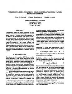
Fig. 1. A general broadband beamforming structure.
is to form a cost function enforcing the frequency invariance requirement in the design and one novel unconstrained least squares(ULS) formulation of the problem is proposed, with its solution based on the eigenfilter method and obtained by finding the minimum generalized eigenvector of two related matrices. This paper is organized as follows. The general broadband beamforming structures are reviewed briefly in Section 2. The ULS formulation for the design of FIBs with its corresponding solution is given in Section 3. Several design examples based on different array structures are provided in Section 4. Conclusions are drawn in Section 5. 2. BROADBAND BEAMFORMING STRUCTURES A general structure for broadband beamforming with tapped delay-lines (TDLs) or FIR/IIR filters is shown in Fig. 1, in which J is the number of delay elements associated with each
2009 International ITG Workshop on Smart Antennas – WSA 2009, February 16–18, Berlin, Germany
y
of the M sensor channels. The beamformer with such a structure samples the propagating wave field in both space and time. Its response as a function of the signal angular frequency ω and the direction of arrival angle θ can be expressed as
signal
m 1
θm
d
θ 0
x
r
˜ R(ω, θ) =
M −1 J−1 X X
M−1
wm,k e−jω(τm +kTs ) ,
(1)
m=0 k=0
where Ts is the delay between adjacent taps of the TDLs and τm is the spatial propagation delay between the m−th sensor and a reference point. We can rewrite the response in a vector form ˜ R(ω, θ) = wT s(ω, θ)
Fig. 2. A uniformly spaced circular array.
z φ
(2)
dy
where w is the coefficient vector defined as w = [w0,0 , · · · wM −1,0 · · · w0,J−1 · · · wM −1,J−1 ]T ,
(3)
θ
and s(ω, θ) is the M × J steering vector given by (4)
where ⊗ denotes the Kronecker product, and sTs (ω) = [1, e−jωTs , · · · , e−j(J−1)ωTs ]T ,
(5)
sτm (ω, θ) = [e−jωτ0 , e−jωτ1 , · · · , e−jτM −1 ω ]T .
(6)
For a uniformly spaced linear array with an inter-element spacing d, we have the spatial propagation delay τm given by τm = mτ1 = m dc cos θ, with the first sensor position as the phase reference point. With the normalized angular frequency Ω = ωTs , ω(mτ1 + kTs ) changes to mµΩ cos θ + kΩ with µ = cTds . Then the steering vector changes to s(Ω, θ) = sTs (Ω) ⊗ sτm (Ω, θ)
(7)
sTs (Ω) = [1, e−jΩ , · · · , e−j(J−1)Ω ]T
(8)
and sτm (Ω, θ) = [1, e
,··· ,e
−j(M −1)µΩ cos θ T
] . (9)
Then we obtain the response as a function of Ω and θ R(Ω, θ) = wT s(Ω, θ) .
y dx
x
s(ω, θ) = sTs (ω) ⊗ sτm (ω, θ)
−jµΩ cos θ
signal
(10)
For a uniform circular array with a circumferential spacing of d, as shown in Fig. 2, we have the spatial delay between the center of the circular array and the m − th sensor, d m) , where r = M τm = r cos(θ−θ c 2π is the radius of the circular
Fig. 3. A uniformly spaced rectangular array, which can be considered as a linear array with SDLs.
array and θm = m 2π M is the angle of the m − th sensor. With the normalized angular frequency Ω = ωTs , ω(τm + kTs ) M changes to Ωβµ cos(θ − θm ) + kΩ with β = 2π . Then we obtain sτm for the uniform circular array case
sτm (Ω, θ)
=
[e−jΩβµ cos(θ−θ0 ) , e−jΩβµ cos(θ−θ1 ) , · · · , e−jΩβµ cos(θ−θM −1 ) ]T .
(11)
When the TDLs in the broadband linear array system shown in Fig. 1 are replaced by sensor delay-lines (SDLs), we will have a rectangular array system without TDLs [24]. Such a structure is shown in Fig. 3, which is an equally spaced rectangular array with M × J sensors and an inter-element spacing of dx and dy , respectively. Without loss of generality, we assume dx = dy = d and the signals come from the direction ϕ = π2 . Since it is a broadband beamforming structure with spatial-only information, we replace kTs in (1) by δk which represents the spatial propagation delay along the y axis and is given by δk = kδ1 = m dc sin θ, with the first sensor position as the phase reference point. With the normalized angular frequency Ω = ωTs , ω(mτ1 + kδ1 ) changes
2009 International ITG Workshop on Smart Antennas – WSA 2009, February 16–18, Berlin, Germany
to mµΩ cos θ +kµΩ sin θ. Then we obtain the steering vector for the rectangular array as s(Ω, θ) = sδk (Ω) ⊗ sτm (Ω, θ)
(12)
PN −1 PK−1 ¯¯ n=0
¯2 wT s(Ωn , θk ) − wT s(Ωr , θk )¯ ¯ ¯2 P + α θk ∈Θs ¯wT s(Ωr , θk )¯
k=0
JU LS =
P
θk ∈Θm
where sδk (Ω, θ) = [1, e−jµΩ sin θ , · · · , e−j(J−1)µΩ sin θ ]T .
(13)
3. THE EIGENFILTER APPROACH TO THE DESIGN OF FIBS In the proposed method, the cost function for the design of FIBs consists of three parts. Firstly, the frequency invariance property is formulated by minimizing the Euclidean distance between the response at a fixed reference frequency Ωr and those at all the other operating frequencies over a range of directions in which frequency invariance is considered. The cost function related to this property is given by Z Z ¯ T ¯ ¯w s(Ω, θ) − wT s(Ωr , θ)¯2 dΩdθ J1 = (14) Ω
(17) where N and K are the number of samples chosen over the frequency and the angle ranges considered for frequency invariance, respectively. Note that the spectrum energy used here is just the summation of energy over the mainlobe at the reference frequency θr , which leads to a much more reduced computational complexity than the conventional methods in the design of broadband beamformers [22]. We can rewrite (17) as JU LS =
Θs
where Θs denotes the sidelobe region. Thirdly, we need to maximize the spectrum energy at the reference frequency Ωr over the mainlobe region. Then, a complete formulation of the FIB design problem is obtained by combining the three elements together ¯ T ¯ R R ¯w s(Ω, θ) − wT s(Ωr , θ)¯2 dΩdθ Ω ΘF I ¯2 R ¯ T + α Θs ¯w s(Ωr , θ)¯ dθ JU LS= (16) R 2 |wT s(Ωr , θ)| dΩdθ Θm where α is a trade off parameter between the frequency invariant property and the sidelobe attenuation. Now let (Ωn , θk ) be the grid chosen from the continuous frequency and angle ranges above. Then the least squares formulation for the FIB design becomes
wT Q1 w wT Q2 w
(18)
where Q1 =
N −1 K−1 X X
|s(Ωn , θk ) − s(Ωr , θk )|2
n=0 k=0
ΘF I
where ΘF I represents a direction range in which frequency invariance is considered. It can be either the main beam direction area or the whole angle range from 0◦ to 180◦ for the linear and planar arrays and from −180◦ to 180◦ for the circular array. Here we will always consider the full angle range. Secondly, we also need to minimize the response of the beamformer at the reference frequency Ωr over the sidelobe region. This part of the cost function is defined as Z ¯ T ¯ ¯w s(Ωr , θ)¯2 dθ J2 = (15)
2
|wT s(Ωr , θk )|
+α
X
s(Ωr , θk )s(Ωr , θk )H
(19)
θk ∈Θs
and
X
Q2 =
s(Ωr , θk )s(Ωr , θk )H
(20)
θk ∈Θm
As Q1 and Q2 are clearly Hermitian, we can obtain wT Q1 w = wT Q1R w and wT Q2 w = wT Q2R w, where Q1R and Q2R are the real symmetric matrices of Q1 and Q2 , respectively. Thus Equation (18) changes to wT Q1R w (21) wT Q2R w Thus the optimal w can be obtained by finding the generalized eigenvector corresponding to the minimum eigenvalue of Q1R and Q2R . Note that the optimum weight vector obtained in this way will not necessarily have a unity response at the look direction θr . To have the desired unity response, we need to normalize the resultant weight vector w. To avoid this normalisation and also have a direct control of the array response to some specific directions, such as a unity response to the desired signal direction, we can follow the total least squares (TLS) approach in the design of broadband beamformers [22] and obtain the following formulation of the problem JU LS =
JCT LS =
wT Q1R w subject to CT w = f, 2R w + 1
wT Q
(22)
2009 International ITG Workshop on Smart Antennas – WSA 2009, February 16–18, Berlin, Germany
where CT w = f provides the desired constraints on the array coefficients. This formulation can be transformed to JCT LS =
ˆ 1w ˆT Q ˆ w ˆw ˆ =0 subject to C T ˆ ˆ ˆ Q2 w w
(23)
ˆ 1, Q ˆ 2 and C ˆ defined as ˆ Q with w, " ˆ1 = ˆ = [w , −1] , Q w T
" ˆ2 = Q
T
Q2R 0
0 1
Q1R 0
0 0
# , (24)
# ˆ = [CT , f] ,C
The solution can be derived in a similar way as in [22]. A problem with this formulation is its high computational complexity and in the design examples, we will only use the formulation given in (21). 4. DESIGN EXAMPLES
Fig. 4. The resultant beam pattern using the ULS formulation for a main beam direction at θ = 90◦ .
To show the effectiveness of the proposed method, we provide several design examples based on a uniformly spaced linear array, a uniformly spaced circular array, and a uniformly spaced rectangular array, respectively. 4.1. Uniformly Spaced Linear Array We apply the proposed method to a uniformly spaced linear array to design FIBs with a broadside main beam, i.e., a look direction θr = 90◦ . The design is based on a linear array with 14 sensors and each followed by an 18-tap FIR filter. The array spacing is assumed to be half the wavelength corresponding to the maximum normalized signal frequency π so that µ = 1. The frequency range of interest in the design is [0.3π, 0.9π] and the mainlobe region is [75◦ , 105◦ ]. The fixed reference frequency point is Ωr = 0.7π and α is set to be 0.05. The resultant beam pattern with the ULS formulation is shown in Fig. 4 which exhibits a good frequency invariant property over the frequency range [0.3π, 0.9π] with a satisfactory sidelobe attenuation. 4.2. Uniformly Spaced Circular Array The proposed least squares approach is general and can be applied to other array structures too. In the following we give an example based on a uniformly spaced circular array with
Fig. 5. The resultant beam pattern using the ULS formulation for the uniform circular array.
2009 International ITG Workshop on Smart Antennas – WSA 2009, February 16–18, Berlin, Germany
6. REFERENCES [1] M. M. Goodwin and G. W. Elko, “Constant beamwidth beamforming,” in Proc. IEEE International Conference on Acoustics, Speech, and Signal Processing, Minneapolis, USA, April 1993, vol. 1, pp. 169–172. [2] T. Chou, “Frequency-independent beamformer with low response error,” in Proc. IEEE International Conference on Acoustics, Speech, and Signal Processing, Detroit, USA, May 1995, vol. 5, pp. 2995–2998.
Fig. 6. The resultant beam pattern using the ULS formulation for the uniform rectangular array with a main beam direction at θ = 90◦ .
14 sensors and each followed by a 20−tap FIR filter. The look direction is θr = 0◦ and the mainlobe region is [−30◦ , 30◦ ]. All of the other parameters are the same as in the linear array case except that α is set to be 0.1. The resultant beam pattern is shown in Fig. 5. Again a good frequency invariant property is achieved over the frequency range of interest. 4.3. Uniformly Spaced Rectangular Array Finally, we apply the proposed method to a uniformly spaced rectangular array without TDLs to design a broadside main beam. Except for the operating frequency range which changes to [0.35π, 0.95π], all of the other parameters are the same as in the linear array case. The resultant beam pattern is shown in Fig. 6, with a good frequency invariance property and a satisfactory sidelobe performance. 5. CONCLUSION A novel least squares formulation to the design of frequency invariant beamformers with an eigenfilter based solution has been proposed, which leads to satisfactory design results as demonstrated by the provided design examples. The proposed approach is general and can be applied to different array structures, such as linear arrays, circular arrays and rectangular arrays.
[3] D. B. Ward, R. A. Kennedy, and R. C. Williamson, “Theory and design of broadband sensor arrays with frequency invariant far-field beam patterns,” Journal of the Acoustic Society of America, vol. 97, no. 2, pp. 1023– 1034, February 1995. [4] T. Sekiguchi and Y. Karasawa, “Wideband beamspace adaptive array utilizing FIR fan filters for multibeam forming,” IEEE Transactions on Signal Processing, vol. 48, no. 1, pp. 277–284, January 2000. [5] L. C. Parra, “Steerable frequency-invariant beamforming for arbitrary arrays,” Journal of the Acoustic Society of America, vol. 119, pp. 3839–3847, June 2006. [6] H. H. Chen and S. C. Chan, “Adaptive beamforming and DOA estimation using uniform concentric spherical arrays with frequency invariant characteristics,” Journal of VLSI Signal Processing, vol. 46, no. 1, pp. 15–34, January 2007. [7] H. H. Chen, S. C. Chan, and K. L. Ho, “Adaptive beamforming using frequency invariant uniform concentric circular arrays,” IEEE Transactions on Circuits & Systems I: Regular Papers, vol. 54, no. 9, pp. 1938–1949, September 2007. [8] S. C. Chan and H. H. Chen, “Uniform concentric circular arrays with frequency-invariant characteristics– theory, design, adaptive beamforming and DOA estimation,” IEEE Transactions on Signal Processing, vol. 55, pp. 165–177, January 2007. [9] W. Liu, S. Weiss, J. G. McWhirter, and I. K. Proudler, “Frequency invariant beamforming for two-dimensional and three-dimensional arrays,” Signal Processing, vol. 87, pp. 2535–2543, November 2007.
2009 International ITG Workshop on Smart Antennas – WSA 2009, February 16–18, Berlin, Germany
[10] W. Liu and S. Weiss, “Design of frequency invarint beamformers for broadband arrays,” IEEE Trans. Signal Processing, vol. 56, no. 2, pp. 860, February 2008. [11] W. Liu, D. McLernon, and M. Ghogho, “Design of frequency invariant beamformer without temporal filtering,” IEEE Transactions on Signal Processing, vol. 57, no. 2, pp. 798–802, February 2009.
tions including Nyquist filters,” IEEE Transactions on Circuits & Systems, vol. 34, pp. 11–23, January 1987. [20] S. C. Pei and C. C. Tseng, “A new eigenfilter based on total least squares error criterion,” IEEE Transactions on Circuits & Systems I: Regular Papers, vol. 48, pp. 699–709, 2001.
[12] W. Liu and S. Weiss, “Off-broadside main beam design and subband implementation for a class of frequency invariant beamformers,” Signal Processing, vol. 89, pp. 913–920, May 2009.
[21] A. Tkacenko, P. P. Vaidyanathan, and T. Q. Nguyen, “On the eigenfilter design method and its applications: a tutorial,” IEEE Transactions on Circuits and Systems — II: Analog and Digital Signal Processing, vol. 50, pp. 497–517, September 2003.
[13] D. B. Ward, Z. Ding, and R. A. Kennedy, “Broadband DOA estimation using frequency invariant beamforming,” IEEE Transactions on Signal Processing, vol. 46, pp. 1463–1469, May 1998.
[22] S. Doclo and M. Moonen, “Design of far-field and nearfield broadband beamformers using eigenfilters,” Signal Processing, vol. 83, no. 12, pp. 2641–2673, December 2004.
[14] W. Liu and D. P. Mandic, “Semi-blind source separation for convolutive mixtures based on frequency invariant transformation,” in Proc. IEEE International Conference on Acoustics, Speech, and Signal Processing, Philadelphia, USA, March 2005, vol. 5, pp. 285–288.
[23] Y. Zhao, W. Liu, and R. J. Langley, “A least squares approach to the design of frequency invariant beamformers,” submitted to IEEE Trans. Signal Processing, December 2008.
[15] W. Liu, R. Wu, and R. Langley, “Design and analysis of broadband beamspace adaptive arrays,” IEEE Transactions on Antennas and Propagation, vol. 55, no. 12, pp. 3413–3420, December 2007. [16] S.F. Yan and Y. L. Ma, “Design of FIR beamformer with frequency invariant patterns via jointly optimizing spatial and frequency responses,” in Proc. IEEE International Conference on Acoustics, Speech, and Signal Processing, Philadelphia, USA, March 2005, pp. 789– 792. [17] H. Duan, B. P. Ng, C. M. See, and J. Fang, “Applications of the SRV constraint in broadband pattern synthesis,” Signal Processing, vol. 88, pp. 1035–1045, April 2008. [18] Y. Zhao, W. Liu, and R. J. Langley, “Efficient design of frequency invariant beamformers with sensor delaylines,” in Proc. IEEE Workshop on Sensor Array and Multichannel Signal Processing, Darmstadt, Germany, July 2008, pp. 335–339. [19] P. Vaidyanathan and T. Q. Nguyen, “Eigenfilters: A new approach to least-squares FIR filter design and applica-
[24] W. Liu, “Adaptive wideband beamforming with sensor delay-lines,” Signal Processing, vol. 89, pp. 876–882, May 2009.