TELKOMNIKA, Vol. 11, No. 12, December 2013, pp. 7094~7101 e-ISSN: 2087-278X
7094
An Embedded Auto-leveling System Based on ARM and FPGA 1
Huaiyu Yang1,2, Youping Chen1, Bing Chen*1
Huazhong University of science and technology, Wuhan 430074 2 Hubei University of technology, Wuhan 430068 *Corresponding author, e-mail:
[email protected]
Abstract A kind of embedded auto-leveling control system based on ARM and FPGA is proposed in this article. According to the mechanical structure and the control requirements of auto-leveling, the system combines the precision and high frequency of ARM with the internal logic configuration of FPGA. The control algorithm, hardware structure and software structure are discussed in the paper. This method not only allows for quicker and easier developing work bur also enhances the flexibility of the controller. The experiments validate the feasibility of system and clearly show that the presented approach is effective to reduce the sliver unevenness. Keywords: ARM, FPGA, auto-leveling, control system Copyright © 2013 Universitas Ahmad Dahlan. All rights reserved.
1. Introduction Drafting stage is indispensable and fundamental operation in whole process of yarn spinning and plays a vital roe for textile quality. The function of drafting is to achieve parallel fibers along the sliver axis and to regularize the evenness of the sliver to get an appropriate thickness for the next procedure. However, the linear density of sliver would be more or less irregular which become more severe with increasing speed after this process because the motion of fibers cannot be completely controlled with rollers during the drafting thus additional irregularities were introduced. The evenness of the sliver is one of the critical factors for producing quality yarn which has an increasingly significant effect on the textile industry. The output irregularities cannot be avoided even with an ideally regular sliver. In principle, there are two approaches to reduce the sliver irregularities. One is to study the drafting mechanism and recognize the causes for irregularities, so that means may be found to reduce them. The other more valuable approach is to use auto-leveling [1]. The second approach is more valuable because it could ease the reliance on external parameters and permit higher drafting speed. To improve the quality of auto-leveling, a number of papers have focused on drafting processes. Just suffice to mention on several recent studies. Many researchers have reported the approach for modeling the drafting process [2] and the dynamic behavior of the flowing bundle [3]. And some investigations are concerned about the effect of the fiber length distribution [4]. Korkmaz and Behery [5] presented the interaction of specific fiber fineness values and the drawing machine. Moreover, many theoretical control approaches also have been tried in auto-leveling, including generalized predictive control theories [6], selfOrganizing and neural network [7], minimum variance control [8], artificial neural networks for determining the leveling action point [9], etc. Sliver irregularities can be attenuated by auto-leveling. With the increasing of drafting speed, it is more difficult to ensure the performance of auto-leveling. Considering the significance of sliver irregularities for further procedures and product, designing a new efficient auto-leveling system is a developing direction of textile manufacture. Although several works have proposed auto-leveling [10-12], some new approaches can get more efficient result as technology evolves. FPGA is the best way to performance a hardware realization at highest sample rate due to its capability to reduce computational burden, and can be used in many applications [13-14]. In view of this situation, the paper will discuss a new embedded auto-
Received June 29, 2013; Revised August 11, 2013; Accepted August 23, 2013
TELKOMNIKA
e-ISSN: 2087-278X
7095
leveling system based on arm and FPGA for high speed drawing frame which is mainly employed to reduce the sliver irregularities. This paper is organized as follows: Electronic differential gear based on synchronization control algorithm is proposed in Section 2, moreover, PID control based on neural network also described in this section. The hardware and software architecture is described in Section 3. Results and analysis is discussed to demonstrate the feasibility and efficiency of the system in Section 4. Finally, a summary with further discussions is given in Section 5 to conclude this paper.
2. Control Strategies 2.1. PID Control based on Neural Network PID control has been considered as one of most widely used strategy in control field for PID controller has good form, robustness and control effect. However, The conventional PID control often can not meet the requirements with the continuous improvement of the system performance. Nowadays, the neural network has been widely used in the control areas with its arbitrary nonlinear function approximation ability and self-learning ability [15-16]. In this paper, the neural network and PID control law are combined to enhance control effect.
i
j
l
x1
kp
x2
ki
x3
kd
wij Figure 1. Block Diagram of Neural Networks PID Control
wli
Figure 2. Diagram of Neural Network
The structure of the PID control based on neural network is illustrated in Figure 1. There are two parts in the system: one is the classic PID controller in which the controller directly controls the object; another part is that neural network adjusts the parameters of the PID controller to achieve the control performance optimization based on the operational status of the system. The outputs in the output layer correspond to the three adjustable parameters proportional gains k p , integral gains
ki and derivative gains kd of the PID controller. The
control performance can be optimized through self-learning and adjusting the weighting coefficients. Three-layer neural network is employed in this paper described in Figure 2. The number of neurons in the input layer is 3, x1 =r(k), x2 = y(k), x3 = e(k), and r (k) is the input of the time k, y (k) is the output of the time k, e (k) is the error value of the time k. The number of neurons in the hidden layer is 5 which can meet the performance requirements. The number of neurons in the output layer is 3 which correspond to the three parameters k p , weight between the input layer and the hidden layer is
ki and kd . The
wij and wli is the weight between the
hidden layer and output layer. The hidden layer is transformed by function:
An Embedded Auto-leveling System based on ARM and FPGA (Huaiyu Yang)
7096
f ( x)
e-ISSN: 2087-278X
e x e x e x e x
(1)
And the output layer is transformed by function:
g ( x)
ex e x e x
(2)
The neural network is trained by the back propagation algorithm to minimize the system error between the output and desired output. The neural network PID control algorithm is as follows: Step 1: Initial parameters: weights .
wij and wli , learning rate and inertia coefficient a
Step 2: Sample r(k), y(k) and compute e(k ). Step 3: Calculate the input and output of the neural network, and the output is
k p , ki ,
kd of PID controller. Step 4: Compute the output u (k ) of PID controller,
u ( k ) u ( k 1) k p ( e ( k ) e ( k 1)) k i e ( k ) k d ( e ( k ) 2 e ( k 1) e ( k 2))
(3)
Step 5: Adjust the weighting coefficients wij and wli . Step 6: Make k=k+1 and return to step 2. 2.2. Synchronization Control Algorithm The key of auto-leveling is to adjust the roller speed of the drafting accessories to change the drafting ratio. The role of control system is to control the servo motor to drive the drafting roller to rotate in accordance with the output command of auto-leveling. Meanwhile, the detection roller and other components must be kept synchronized with the drafting roller to avoid unexpected draft. Therefore, the roller motion control is essentially a multi-motor synchronized motion control. In contrast with the traditional mechanical differential gear box, the method of multi-motor drive improves the operating speed of the system and the dynamic response capability but it is more difficult to keep the stability of the motor speed to avoid speed fluctuations resulting in additional short segments uneven.
Figure 3. Block Diagram of Electronic Differential Gear Multi-motor synchronization control has been extensively discussed in the field of motion control, but the application for auto-lelveling possesses unique difficulties. So, an
TELKOMNIKA Vol. 11, No. 12, December 2013: 7094 – 7101
TELKOMNIKA
e-ISSN: 2087-278X
7097
electronic differential gear structure is proposed in this paper to achieve a decoupling between the auto-leveling control and synchronization control. The structure is shown in Figure 3. The frequency divider can achieve any electronic gear ratio which can replace the gear teeth adjustment of the mechanical differential gear box. The control command signals are preprocessed by digital filter including low-pass filtering and necessary band-stop filtering to eliminate the interference and noise and frequency band signal which can cause mechanical equipment resonance. The pulse generator transforms the output signals from the digital filter into pulse signals: the positive pulse output terminal of the pulse generator outputs pulses when gets positive signals, if not, the negative pulse output terminal outputs pulses. The pulse generator will not output simultaneously the positive and negative pulses and the frequency of the output pulses is proportional to the output signal amplitude from digital filter. The pulse signals from the frequency divider will be accurately measured frequency by the speed measurement module for speed synthesis. The output pulses from the frequency divider and the pulse generator are superimposed by pulse synthesizer. Within a fixed time, if the number of pulses from the frequency divider is M, the number of positive pulses is N1 and the number of negative pulses is N2, then the output pulses number from pulse synthesizer is M+N1-N2 which are transmitted to the position loop of the second roller motor driver as a position command, i.e. the number of output pulses within the unit time corresponding with the motor displacement of the second roller in the unit time. The output value of speed measurement and the output value of the digital filter are superimposed by the velocity synthesizer to obtain the speed commands which are transmitted to the position loop for the second roller motor driver as feed forward signals. The superiority of the electronic differential gear is to achieve the decoupling control between auto-leveling control and motor synchronization control, namely, electronic differential gear has the same stiffness as mechanical differential gear box if auto-leveling algorithm can give appropriate differential control signals to electronic differential gear based on the mass density of the input sliver and the dead zone length. Moreover, the new structure keeps the merit of good synchronization and strong anti-jamming capability as the traditional mechanical differential gear box and enhances the flexibility, responsiveness and reliability of the control system.
3. Hardware and Software Architecture 3.1. Hardware Architecture The auto-leveling control system discussed in the paper is a high-speed digital system. According to the actual application, the system needs to meet the following performance: highfrequency and computing performance, floating-point computing power, the integration of multiple communication protocols and configuration and scalability.
Figure 4. Hardware Structure Diagram of Auto-leveling System
Based on consideration mentioned above, the framework of ARM and FPGA is selected as Figure 4. ARM is the CPU of control system which is responsible for the control algorithm computing, digital signal processing, human-computer interaction, and system An Embedded Auto-leveling System based on ARM and FPGA (Huaiyu Yang)
7098
e-ISSN: 2087-278X
software maintenance. FPGA is in charge of the interface expansion and drive, coordinating the signal interface and A/D, D/A converting.
3.2. Software Architecture Software flowchart of auto-leveling system is shown in Figure 5. Firstly, a large number of system configurations of ARM chip need to be completed including storage space, interrupt vector table, the system clock, etc. then initialize interface functions such as UART communication, I/O, FlexBus and others. System parameters, auto-leveling parameters and PID parameters are read from the MRAM and Flash. After that open interrupt system and realtime tasks which may be interrupt background program at any time, background processing start and operate in order.
Figure 5. Software Flowchart of Auto-leveling System
Open loop control is employed in the auto-leveling system in which there is a time delay between sampling point and leveling point. Control system detects the thickness of the feeding sliver at intervals of a certain length (fixed length sampling) or a predetermined time (timed sampling). When the sampling point reaches the leveling point after a certain time, the servo motor changes speed to adjust the draft ratio. The system is initialized then enters a cyclical operation of auto-leveling control. To begin with, Control loop reads information of sampled sliver thickness and save it to the FIFO, and then accumulate the sampling times to calculate sliver displacement by the accumulated value. Compare the displacement with the length of the dead zone, Remove the sliver thickness values from the FIFO and calculate the drafting ratio which will be translated into control parameters to servo motor if both are equal. The delay is the key to the open loop control which directly affects the final leveling effect.
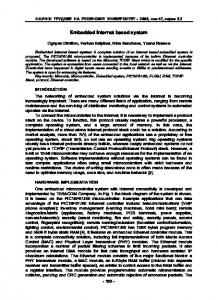
4. Results and Analysis In order to verify the effectiveness of the presented system in the paper, we mounted the controller on the drawing frame of Tianmen Textile Machinery. Table 1 shows specifications of the material used and the drafting conditions for the experiments. As a demonstration, the response of output linear density which seven slivers are combined to one sliver by the controller is shows in Figure 6. There are two important TELKOMNIKA Vol. 11, No. 12, December 2013: 7094 – 7101
TELKOMNIKA
e-ISSN: 2087-278X
7099
indicators about auto-leveling effect, namely the yarn evenness (CV %) and weight unevenness. The effect of auto-leveling system based ARM and FPGA is shown in Table 2 in which the comparisons of sliver evenness performance are made by the CV%. Compared to the testing results without auto-leveling control, the CV% values are decreased obviously and demonstrate small variation. As can be seen, the improvements of CV% by the auto-leveling control are considerable. Data in Table 3 shows the weight of sliver every one meter. The minimum is 5.21 and the maximum is 5.35 and the average weight is 5.269. The most data are between 5.25 and 5.29which obey the normal distribution. By calculating the data, the weight unevenness of one meter is 0.36% which is close to the desired value.
Table 1. The Material used and the Drafting Conditions for the Experiments Parameter Material Number of doublings Roller gauge length, mm Drafting ratio
main break main break total
Delivery speed, m/min Machine type
Value Combed cotton sliver 7 47 41.5 4.69 1.36 6.38 522 TFD81L
Figure 6. Response of Output Linear Density
Table 2. Comparison of Sliver CV% No control Control
2.65 2.45
3.02 2.59
2.77 2.60
CV% 2.81 2.47
3.05 2.61
3.40 2.96
3.23 2.54
Table 3. The Weight of Sliver every One Meter Sample data 5.22
5.23
5.29
5.28
5.29
5.31
5.25
5.30
5.29
5.27
5.24
5.26
5.25
5.26
5.26
5.26
5.31
5.28
5.28
5.24
5.25
5.26
5.27
5.26
5.26
5.30
5.31
5.34
5.30
5.28
5.26
5.28
5.31
5.30
5.29
5.24
5.25
5.27
5.28
5.26
5.29
5.30
5.28
5.25
5.22
5.23
5.23
5.26
5.27
5.25
5.23
5.26
5.23
5.21
5.24
5.28
5.28
5.25
5.27
5.26
5.24
5.29
5.24
5.27
5.26
5.28
5.35
5.29
5.26
5.31
5.26
5.27
5.28
5.26
5.26
5.27
5.29
5.25
5.27
5.28
5.27
5.27
5.28
5.30
5.27
5.30
5.24
5.28
5.27
5.26
5.27
5.28
5.25
5.28
5.25
5.27
5.24
5.23
5.28
5.29
An Embedded Auto-leveling System based on ARM and FPGA (Huaiyu Yang)
7100
e-ISSN: 2087-278X
In addition, we compared the auto-leveling system with Uster controller which is a leader of quality control for textile industry in same condition. As shown in Table 4, the sliver weight every five meters are regulated in both Uster and the control system presented in the paper, whereas the most max error of this paper are smaller than Uster system which mean the better weight unevenness. Table 5 shows the comparison of CV%, these results suggest that the effect of the proposed control sys tem is either close to or slightly better that of Uster.
Table 4. Comparison of Weight every Five Meters Sample 1 2 3 4 5
Control system
Max error
Sample data
Uster
25.31
25.51
25.41
25.28
25.32
25.39
25.21
25.31
25.42
25.29
0.30
The paper
25.08
25.18
25.04
25.11
25.09
25.13
25.14
25.11
25.23
25.14
0.19
Uster
25.51
25.69
25.45
25.31
25.48
25.43
25.51
25.32
25.42
25.51
0.37
The paper
25.71
25.56
25.59
25.59
25.70
25.61
25.50
25.56
25.55
25.60
0.21
Uster
25.30
25.36
25.16
25.28
25.41
25.23
25.24
25.39
25.10
25.27
0.25
The paper
25.17
25.23
25.29
25.30
25.30
25.11
25.23
25.39
25.16
25.21
0.28
Uster
25.15
25.04
25.10
25.15
25.28
25.25
25.33
25.11
25.19
25.24
0.29
The paper
24.93
24.90
24.93
24.95
25.04
24.90
25.11
25.01
24.98
25.03
0.21
Uster
25.19
25.21
25.35
25.29
25.40
25.29
25.26
25.20
25.28
25.33
0.21
The paper
25.11
25.09
24.99
25.12
25.14
25.07
25.11
25.10
25.04
25.06
0.15
Table 5. Comparison of CV% Control system No control CV% Control
2.13 1.83
Uster 2.18 1.84
The paper 2.29 1.92
2.56 1.93
2.09 1.81
2.19 1.85
5. Conclusion The work discussed in the paper emerged from the need of quality control in yarn spinning. It has already been pointed out that auto-leveling is a more valuable approach to reduce the sliver irregularities. In this paper, a kind of embedded auto-leveling control system based on ARM and FPGA is proposed. First, PID control based on neural network and Electronic differential gear based on synchronization control algorithm are described. Second, the hardware architecture and software architecture are presented. Finally, the experiments and applications validate the feasibility of system and clearly show that the presented approach is effective to reduce the sliver unevenness. The research results could be applied to yarn spinning and contribute to improving product quality. However, there exist still many factors working together in affecting the sliver unevenness, thus the further work need to be studied to improve the textile quality.
Acknowledgement The work is supported by the National Nature Science Foundation of China (No. 51105154).
References [1] Huang CC, Chang KT. Fuzzy Self-organizing and Neural Network Control of Sliver Linear Density in Drawing Frame. Textile Res. 2001; 71(11): 987–992. [2] Djiev SN. Modeling a Double-Zone Drafter as an Object of Control. Textile Res. 1994; 64(8): 449456. [3] Huh Y, Kim JS. Modeling the Dynamic Behavior of the Fiber Bundle in a Roll-Drafting Process. Textile Res. 2004; 74(10): 872–878. [4] Yan GS, Yu CW. The Influence of Fiber Length Distribution on the Accelerated Points in Drafting: A New Perspective on Drafting Process. Fibers and Polymers. 2009; 2(10): 217–220.
TELKOMNIKA Vol. 11, No. 12, December 2013: 7094 – 7101
TELKOMNIKA
e-ISSN: 2087-278X
7101
[5] Korkmaz YA, Behery HM. Drafting Dynamics of Fine Denier Polyester Fibers. Textile Res. 2004; 74(6): 497–501. [6] Guo YY, Chen RQ, Hu JL. Applying a Generalized Predictive Control Theory to a Carding Autoleveler. Textile Res. 2003; 73(9): 755–761. [7] Huang CC, Chan KT. Fuzzy Self-Organizing and Neural Network Control of Sliver Linear Density in a Drawing Frame. Textile Res. 2001; 71(11): 987–992. [8] Huang CC, Bai JC. Minimum Variance Control in Leveling Slivers. Textile Res. 2001; 71(7): 621-625. [9] Farooq A, Cherif C. Use of Artificial Neural Networks for Determining the Leveling Action Point at the Auto-leveling Draw Frame. Textile Res. 2008; 78(6): 502–509. [10] Sheldon RC, Roach RA, Backer S. Design of an On-Line Computer-Based Textile Information Retrieval System. Textile Res. 1968; 38(8): 81–100. [11] De SK. A Microprocessor-Based Sliver-Unevenness Analyze. Textile Res. 1981; 51(6): 426–431. [12] Zhu KY, Zou ZM, Li CX. A new control system for auto-leveling of high speed drawing frame. Adv Manuf Technol. 2007; 34: 156-160. [13] Sutikno T, Idris NRN, Widodo NS, Jidin A. FPGA Based a PWM Technique for Permanent Magnet AC Motor Drives. International Journal of Reconfigurable and Embedded System. 2012; 1(2): 43-48. [14] Sutikno T, Idris NRN, Jidin AZ, Jidin A. A Model of FPGA-based Direct Torque Controller. TELKOMNIKA Indonesian Journal of Electrical Engineering. 2013; 11(2): 747-753. [15] El-Madany HT, Fahmy FH. Design of FPGA Based Neural Network Controller for Earth Station Power System. TELKOMNIKA Indonesian Journal of Electrical Engineering. 2012; 10(2): 281-290. [16] Melin P, Herrera V, Romero D, Valdez F. Genetic Optimization of Neural Networks for Person Recognition based on the Iris. TELKOMNIKA Indonesian Journal of Electrical Engineering. 2012; 10(2): 309-320.
An Embedded Auto-leveling System based on ARM and FPGA (Huaiyu Yang)