International Journal on Advances in Software, vol 8 no 1 & 2, year 2015, http://www.iariajournals.org/software/
125
Towards a Classification Schema for Development Technologies: an Empirical Study in the Avionic Domain Davide Taibi, Valentina Lenarduzzi Free University of Bolzano-Bozen Bolzano-Bozen, Italy
Laurent Dieudonné Liebherr-Aerospace Lindenberg, Germany
{davide.taibi, valentina.lenarduzzi}@unibz.it
[email protected]
Christiane Plociennik University of Kaiserslautern Kaiserslautern, Germany
[email protected] Abstract— Software and hardware development organizations that consider the adoption of new methods, techniques, or tools often face several challenges, namely to: guarantee process quality, reproducibility, and standard compliance. They need to compare existing solutions on the market, and they need to select technologies that are most appropriate for each process phase, taking into account the specific context requirements. Unfortunately, this kind of information is usually not easily accessible; it is incomplete, scattered, and hard to compare. Our goal is to report on an empirical study with high-level practitioners, to extend our previous work on a classification schema for development technologies in the avionic domain. We investigate the acceptance and the possible improvements on the schema, with the aim to help decision makers to easily find, compare and combine existing methods, techniques, and tools based on previous experience. The study has been carried out with five technical leaders for the development of flight control systems, from Liebherr-Aerospace Lindenberg GmbH and the results show that the schema helps to transfer knowledge between projects, guaranteeing quality, reproducibility, and standard compliance. Keywords-component; process improvement; technology classification; technology selection; tool selection; method selection; process configuration.
I.
INTRODUCTION
The definition of a product development process that guarantees quality and reproducibility often takes years. Moreover, in certain domains, such as avionics, the process must comply with a set of standards. The introduction of a new technology may break the consistency and standards compliance of the process. To limit this risk, two major aspects must be considered. First, the objectives and prerequisites for each process step must be fully documented and structured. Second, the contribution of each method and tool intended to be used, must be limited to the objectives set by each domain process activity and their role in each process step must be fully described. A structuring framework, enabling the classification of the technologies in process activities would speed up the integration of new technologies and contribute to guaranteeing compliance with the company processes.
To facilitate the classification of technologies, the Reference Technology Platform (RTP) has been developed. RTP is a set and arrangement of methods, workflows, and tools that allow interaction and integration on various levels in order to enable efficient design and development of (complex) systems [1] [3]. In the context of the ARAMiS project (Automotive, Railways, Avionics Multicore Systems) [4], a classification schema based on the RTP has been developed. It classifies technologies along two dimensions: abstraction levels and viewpoints. In our previous work, we introduced how RTP and Process Configuration Framework (PCF) could have been applied in the avionic domain [1]. The goal of this paper is to conduct an empirical study with the goal of evaluating the RTP and PCF approaches, for the purpose of understanding their acceptance and applicability to the selection process, in the context of new product development in the avionic domain. For this purpose, in this paper, we present the results of the case study proposed in [1] and we conduct an empirical study so as to validate the approach with high-level practitioners from Liebherr-Aerospace. The results of this work suggest that the classification provides a useful framework for decision makers and allows them to base their decisions on previous experience instead of on personal opinions. Moreover, the classification allows them to guarantee process quality, reproducibility and standards compliance, facilitating knowledge transfer from project to project or between employees. The remainder of this paper is structured as follows: Section II describes related work; Section III introduces the classification schema and its implementation in PCF, while Section IV describes the avionic use case. In Section V, we describe the Empirical Study while in Section VI we report results of the study. Finally, we draw conclusions in Section VII and provide an outlook on future work. II.
RELATED WORK
Here, we present some common technology classification schemas. In 1987, Firth et al. published an early classification schema [5]. In this work, software development methods are
2015, © Copyright by authors, Published under agreement with IARIA - www.iaria.org
International Journal on Advances in Software, vol 8 no 1 & 2, year 2015, http://www.iariajournals.org/software/
126 classified according to two dimensions: the stages of the development process (specification, design, and implementation) and the view (functional, structural, and behavioral). The stages are specification, design, and implementation; the views are functional, structural, and behavioral. Our schema, too, is two-dimensional, and our viewpoints dimension is similar to the views dimension of Firth et al. However, Firth et al.'s second dimension is concerned with the process stages, which we map onto the viewpoints dimension. Instead, the second dimension in our schema is concerned with abstraction levels. In the late 1980's, the idea of the Experience Factory was first published [6]. It was then updated in 1991 [7] and in 1994 [8]. The idea is to describe software development artifacts in so-called experience packages and to include empirical evidence on how these artifacts have been used previously. This way, the Experience Factory provides a comprehensive framework for the reuse of software. The goal is to enable software engineers to base their decisions on company experience. The Experience Factory is a more general concept than ours. In the Experience Factory, any software engineering artifact can be an object for reuse, e.g., products or requirements documents. Moreover, a specific schema for storing different technologies for reuse is not provided in the Experience Factory. Neither does it include any algorithms to search for or to combine technologies. The C4 Software Technology Reference Guide (C4 STR) is a catalog that contains more than 60 technologies. It constitutes an alternative approach to technology classification and was developed in parallel to the later versions of the Experience Factory. In comparison to our work, the C4 STR schema includes a large number of technologies. However, the attributes it uses are not as detailed as those in our schema, and it includes no reference to context or to impact. Later, Birk merged the Experience Factory approaches with the C4 STR [8]. This evolved into the concept of experience management in the late 1990's. This work served as the basis for other publications that evolved this schema and extended the idea of the Experience Factory [9]. A classification schema for software design projects was developed by Ploskonos [10]. With the help of this schema, generic process descriptions and methods can be adapted to individual processes more easily. It classifies design projects into one of the four groups Usability, Capability, Extension, and Innovation. Each of these groups is associated with specific process characteristics in order to help the user in setting up the actual process. Ploskonos' approach is more narrow than ours: It classifies processes with respect to the project type, ignoring other characteristics, e.g., project size or domain. III.
THE CLASSIFICATION SCHEMA
As a foundation for the case study, which we present in the next section, we now introduce the classification schema we applied. The goal of the schema is to provide a complete engineering tool chain that can be used to collect and
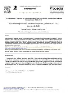
integrate technologies. This way, the schema supports the activities required for a structured development process. With our schema, we address the development of industrial projects that are big and complex. Typically, such projects run several years and require the joint efforts of many employees. In the industry, requirements-based process models are commonly used to plan the different baselines and to ensure that these baselines are accomplished on time in different phases of realization. Usually, every phase and every step of the processes produces artifacts which then constitute the inputs for the next phase(s) or step(s). These process models are based on, or are extensions of, the V-Model [11]. An instance of the V-Model for the avionics domain is shown in Figure 1. It is an extract of the avionics standard SAE ARP4754A [12], and it includes the interaction between both avionics development and safety integral processes. Traditionally, the V-Model is used in the iterations that are carried out in order to accomplish each baseline. In addition to the iterations, concepts such as the definition of phases, the definition of objectives, periodical assessments, the definition of roles, and traceability (forward and backward) are traditionally included in these development processes. Current agile methodologies, like SCRUM [11], have also been inspired by these concepts. The schema we present in this paper serves as a generic development model that covers the industrial development processes. Naturally, the instances of this generic development model depend both on the development standards in the industry and on the particular company. Using the information provided in the schema, decision makers can find the most appropriate technologies based on the technologies' interaction and integration on multiple levels. This helps to efficiently design and develop complex systems. Moreover, the schema may provide an overview of the tools and methods used in previous projects. As the activities inherent to the industrial processes (e.g., planning phases, assessment meetings and accomplishment summaries) are performed periodically throughout each project development, a huge amount of data can be collected during the development life cycle of every project. This data includes, for example, the decisions made, or the quality and special uses of the tools, technologies and methods. This helps to build a knowledge base that is adapted to the company's development processes and addresses best practices as well as pitfalls. Thus, new projects can benefit from prior experience instead of starting from scratch. Furthermore, the schema can help new employees to quickly become familiar with the tools and methods available in the company for every phase of the development process fostering knowledge transfer within a company. Inspired by the work done in SPES2020 [13] and SPES_XT [14], our schema can be envisaged as a twodimensional matrix, where viewpoints form the columns and abstraction levels form the rows. The viewpoints dimension consists of “Requirements”, “Functional”, “Logical”, and “Technical”.
2015, © Copyright by authors, Published under agreement with IARIA - www.iaria.org
International Journal on Advances in Software, vol 8 no 1 & 2, year 2015, http://www.iariajournals.org/software/
127
Figure 1: Avionics V-Model extract from the ARP4754A [12]
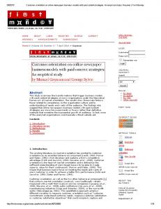
Figure 2: Generic representation of our classification schema
Those four viewpoints can be mapped to the three phases of the development process: the requirements viewpoint corresponds to the requirements capture phase, the functional and logical viewpoints can be mapped onto the design phase, and the technical viewpoint corresponds to the construction or implementation phase (see Figure 2). Figure 2 depicts the generic version of the schema. The abstraction levels correspond to different decompositions of the system. These are (from coarse-grained to fine-grained): system, subsystems, components, and units. This generic set of abstraction levels can be substituted by different, domainspecific abstraction levels according to the specific
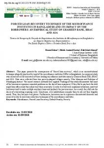
application domain (automotive, railways, avionics etc.). For instance, the avionics domain defines the following abstraction levels (see Figure 3): “Aircraft”, “System”, “Equipment”, and “Item”. Each step of the product development process that must be carried out is represented as a cell in the schema, to be traversed from the top left cell to the rightmost. This is represented by the arrows in Figure 2 and Figure 3. Each step produces artifacts as outputs. These outputs may contribute directly to the accomplishment of the process objectives required by the domain, or indirectly if they serve as inputs for other cells in later steps. The objectives specified by the domain process depend on the development phase and the abstraction level. Here, we explain how the matrix is traversed, as shown in Figure 3. We start at a given abstraction level. First, the requirements related to this abstraction level are recorded in the requirement viewpoint. The outputs of this viewpoint are the filtered requirements, applicable for the (sub…)system under focus. They are needed in order to start the design of the (sub…)system. The design phase comprises the functional and the logical viewpoint. In the functional viewpoint, the network of functions representing the system workflow is determined. It is then undertaken into the logical viewpoint, where a structuration (decomposition and/or composition) of the identified functions is performed. If the objectives of the logical viewpoints are fulfilled, we move on to the technical viewpoint. Here, the construction of the system is started.
2015, © Copyright by authors, Published under agreement with IARIA - www.iaria.org
International Journal on Advances in Software, vol 8 no 1 & 2, year 2015, http://www.iariajournals.org/software/
128
Figure 3: Example of classification schema for the avionics domain.
Sometimes iterations must be carried out, e.g., to introduce new requirements or to incorporate realization constraints that appear a posteriori and that influence the design of the system. If not all requirements derived from the design (and hence from the requirement viewpoint) have been fulfilled at the end of the abstraction level, the unfulfilled requirements are used as a basis in the next abstraction level. They are recorded in the requirement viewpoint of this new current abstraction level. Now the steps described above for the previous abstraction level are carried out again for the next abstraction level. In order to foster partial and iterative development, a set of transition criteria is defined. These transition criteria control the transition from one cell to the next. With the help of transition criteria, it is possible to evaluate the risks of commencing the next development step if not all objectives of the current step are fulfilled. It is then possible to control the current status of fulfillment of the objectives, which will be realized after several iterations. In order to fulfill the objectives of each step, the methods used by the system and software engineers are usually supported by tools. Which methods and tools are required depends on the specific characteristics of the respective development process: the category of product that is to be developed, the requirements, the abstraction level, and the focus of the current development iteration (e.g., the objectives to be addressed). Furthermore, the integration of the technology chain used may also differ. The methods must as well support the transition criteria between the process steps. A. The implementation of the classification schema in PCF The proposed schema has been implemented as a web application in the PCF tool [15]. PCF is an online platform, developed by means of the Moonlight SCRUM process [16][17]. PCF allows users to search for technologies based on abstraction levels and viewpoints as defined in the schema. Furthermore, PCF adds two more aspects to provide
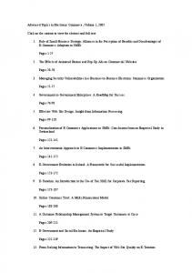
information about previous experience using a specific technology: Context and Impact. Hence, the data schema in PCF is based on three models as defined in [18] (as shown in Figure 6): • Technology: includes a set of attributes for describing a technology in as much detail as possible. • Context: includes information on the context, such as application domain, project characteristics, and environment in which the respective technology has been applied. • Impact: includes previous experience on applying a specific technology in a specific context. The PCF tool contains a search feature that allows users to search for technologies based on the attributes defined in the models in Figure 6. This enables the user to search for technologies used in projects with specific characteristics, e.g., projects fulfilling a certain industrial standard. Basic use cases for PCF, as shown in Figure 4, are: • Search for a technology based on context requirements (not mandatory) o List view o Matrix view • View details for a technology • View related context • View details for a context • View related impacts • View details for a related impact Moreover, PCF implements the schema for different domains (avionics, automotive, and railways). Figure 5 shows an example of the schema represented in PCF for the avionics domain. This figure includes the methods mentioned in the use case or directly the tools realizing them, as well as several other technologies for the avionics domain in addition to those mentioned above. In this version of the tool, we do not consider interoperability issues. The next version of the tool will address the challenge of interoperable tool chains.
2015, © Copyright by authors, Published under agreement with IARIA - www.iaria.org
International Journal on Advances in Software, vol 8 no 1 & 2, year 2015, http://www.iariajournals.org/software/
129
Figure 4: PCF Use Cases
Traditionally, at the aircraft and system abstraction level, but also partly persistent at the lower levels, mainly few and text-based tools (IBM Rational DOORS, MS-Excel, MSWord, …) are used, completed pointwise with advanced graphical tools (MS-Visio, etc.) for architecture overview, and with specific tools simplifying the validation and verification of the system under development. Model-based methods and tools appears more and more for parts of the functional aspects needing to be simulated, or where better structuration, formalization and automation can be obviously performed to save time and money (SysML/UML technologies, MATLAB/Simulink, ESTEREL Scade, etc.). The model-based development methods facilitate an overview of the system, but need a strong defined formalism to be uniquely understandable. Structured text can be more precise with less formalism, but for big projects, many additional informative descriptions or pictures are needed to keep the red line with acceptable workload, in particular for engineers having to work with these requirements for the next development step. A mix of the both methods is probably the most efficient, if interoperability between the tools is provided. Both are also accurate enough to ensure exact traceability with a minimum of orderliness. Thanks to the structured methodology, to the overview and to the collection of experience enabled by the PCF, development tools offering more automatisms but also being complex to integrate, can be easier incorporated in development processes. An example of possible enhanced tool environment is done in Figure 5. Some details about inputs-outputs are given in section IV, but it is not the goal of this paper to describe the details of use of each tool – this is also depending of company processes. Attributes to evaluate the quality, the adequacy and the added value of the tool are integrated in the PCF template by filling the technology, context and impact information like defined in Figure 6. For example, a tool having a qualification kit for the automation of a specific process step (e.g., code generation with ESTEREL Scade) provides a substantial advantage by avoiding manual work like a review activity, which saves much development time.
But its integration in the development process has also an impact on recurring and non-recurring costs, among other concerning purchase, training or maintenance fee. At the end, a trade-off decision must be taken to select the adequate chain of technologies and tools which could support an optimal project budget.
Figure 5: An example of the schema in the avionic domain implemented in PCF.
IV.
APPLYING THE CLASSIFICATION SCHEMA IN THE AVIONIC DOMAIN
In this section, we sketch an example of a use case of the classification schema in the avionics domain. In the avionic industry, two main processes are defined and address two different aspects corresponding to the two branches of the V-Model: the Development Process and the Integral Process [12] (see Figure 1). The combination of both main processes defines abstraction levels (Aircraft, System, Equipment/Item, Software, Hardware, etc.) and specific processes for each of them. Iterations can be done inside an abstraction level, or inclosing them.
2015, © Copyright by authors, Published under agreement with IARIA - www.iaria.org
International Journal on Advances in Software, vol 8 no 1 & 2, year 2015, http://www.iariajournals.org/software/
130
Figure 6: PCF Data Schema.
The overall resulting applicable development process can be summarized like the following suite of development phases, where the previous ones are required by the next ones: Aircraft Requirements Identification, Aircraft Function Development, Allocation of Aircraft Function to Systems, System Requirements Identification, Development of System Architecture, Allocation of System Requirements to Items, Item Requirements Identification, Item Design (corresponds to Software and Hardware Development, both having specific processes), Item Verification, System Verification, and Aircraft Verification. These different phases can be well mapped onto the generic development model, by instancing the abstraction levels and by specifying the objectives of the viewpoints for each abstraction level, according to the company and project needs. For example, at the system level, the System Requirements Identification corresponds to the Requirement Capture Viewpoint, the Development of System Architecture is realized via the Functional and Logical Viewpoints, the Allocation of System Requirements to Items belongs to the Technical Viewpoint, where the decision is taken on which technology will be involved to realized the Items (Item Design corresponds to Software and Hardware development). The Verification phases are realized in the Technical Viewpoint of corresponding abstraction levels, where the integration activity is performed. For each phase, objectives concerning safety assessments, validation, verification, etc. are defined via the Integral Process and should be met in order to move to the next phase, or must be accomplished during a next iteration. The same logic applies when moving to the next abstraction level. Identical principles apply for all the other abstraction levels. This is also true for the Software and Hardware development, but with different steps inside the phases and different objectives, because they are defined by specific processes specified in the avionics standards DO-178C [2] and the DO-254 [19].
We consider the development of a safety-critical system – a Flight Control System (FCS). We give an example on how the regular avionic development process, according to the civilian aircraft and systems development process guidelines ARP4754A [12], can be mapped on the classification schema (see Figure 2). This mapping is shown in Figure 3, where the different represented process artifacts originate from the avionics V-Model depicted in Figure 1. Here, we briefly introduce how to use the classification schema efficiently by describing the most important development process steps and their artifacts. The example summarized below starts at the system abstraction level. It follows the simplified process instance shown in Figure 3. Based on the high-level aircraft requirements and design decisions, the requirements on the FCS must first be captured, expressed, and validated precisely (requirement viewpoint). The artifacts for this step are the functional and non-functional requirements that contain the goals of the system (e.g., “control the three axes of the aircraft: pitch, yaw, and roll”), the operational requirements (e.g., operational modes), the safety requirements (e.g., which criticality for which surface/axis), the high-level performance requirements (e.g., aircraft response time following cockpit control requests), etc. The requirement capture can be facilitated with model-based methods, for example by using context, use-cases and scenarios diagrams representable with SysML/UML diagrams and elements among other supported by the tools Enterprise Architect (Sparx Systems) or Artisan Studio (Atego), or with requirements tools using structured text, like with DOORS (IBM Rational) – see Figure 5, cell “System – Requirement”. Once captured, the requirements must be validated, which is a transition criterion for proceeding to the next step. Different activities and requirements types are analyzed using different technologies, according to the avionics standards. For this step, manual reviews are performed. These requirements, expressed as text, model or in-toolsintegrated mix of both, are then considered as valid inputs for the design phase. Based on them, the behavior of the
2015, © Copyright by authors, Published under agreement with IARIA - www.iaria.org
International Journal on Advances in Software, vol 8 no 1 & 2, year 2015, http://www.iariajournals.org/software/
131 system is analyzed and a functional architecture in the form of a network of the essential functions covering the major system functionalities must be formulated (functional viewpoint). An example of a major functionality at the system abstraction level is the altitude control via the pitch axis, which is realized by the elevator surfaces. Essential functions are those realizing the functionality and having an external interface with other parts of the system, for example actuator control, acquiring of the surface position, synchronization with the other surfaces, etc. For example, block definition diagrams from the SysML (e.g., with Enterprise Architect, Artisan Studio, …) and signal flow diagrams (e.g., with MATLAB/Simulink from The Mathworks) are suitable to model the functions network (Figure 5, cell “System – Functional”). The resulting functional architecture shapes a part of the outputs of this step. First simulations of the system overall behavior can be realized with MATLAB/Simulink and some SysML/UML tools supporting model execution (e.g., Artisan Studio). This contributes to an early system validation. Once the definition of these functions and their related requirements is completed, a Functional Hazard Assessment (FHA) must be performed [12], still in the functional viewpoint, like shown in Figure 3. The resulting FHA requirements express a fundamental output required by the avionics process at the system design phase. The FHA produces safety requirements and design constraints for the next design step (inside the logical viewpoint) which are necessary to make decisions about the decomposition and structuration of the functions in order to realize a suitable system design. In the logical viewpoint (Figure 3, cell “System – Logical Viewpoint”), these essential functions are structured, completed, and/or decomposed in order to shape the components to be realized on this abstraction level – here named “logical components”. The logical architecture determination is also efficiently supported by the SysML/UML technologies (block diagrams, activity diagrams) and tools, and the behavior can be well designed via control flow diagrams, state machines, etc., among other supported by MATLAB/Simulink (Figure 5, cell “System – Logical”). Both categories of artifacts serve the expression of the required output of the system design phase (system architecture, interfaces definition, behavior details). At the end of the logical viewpoint, different validation activities (part of the transition criteria) must be accomplished, like a Preliminary System Safety Assessment (PSSA), a preliminary common cause analysis (CCA), etc. [12] in order to validate the decisions made in the design phase, that is, in the functional and logical viewpoints. Simulation technologies (e.g., MATLAB/Simulink) can also be used to validate the interactions and behavior between the logical components, once they are correctly formalized. Based on these components and their inherited requirements (the logical components are derived from the functions of the functional viewpoint, which are themselves derived from the requirements of the requirement viewpoint), technical solutions suitable for this abstraction level are identified or existing technical solutions are chosen (technical viewpoint, see cell “System – Technical
Viewpoint” in Figure 3). These technical solutions are called “technical components” in this paper. The requirements expressed by the logical components drive the selection of the technical components. At the system (and equipment) abstraction level(s), the technical viewpoint contains the allocation activities like defined in the avionic process [12] and shown in Figure 1. Systematic methods and semiautomatic deployment tools can support the allocation activity. Common activity to all abstraction levels, the new developed, previously integrated or already existing technical components are integrated in the above abstraction level. These integrated components represent the major outputs of the technical viewpoint. Iterations inside an abstraction level are feasible for introducing new requirements, or for increasing the reusability rate by considering already existing technical components. As a consequence, the structuring (decomposition and composition) of the logical components may be performed in a different way. A configuration management system is mandatory for managing the different alternatives and versions. At the end of the technical viewpoint, different verification activities must be accomplished, depending on the abstraction level. At the system (and aircraft) one(s), a System Safety Assessment (SSA), a common cause analysis (CCA), etc. [12] are performed in order to verify the decisions made in the functional, logical, and technical viewpoints. These safety process verification activities are shown in Figure 3 and Figure 5 (e.g., cell “System – Technical Viewpoint”). For functional verification, generic tools and methods supporting these activities are very specific to the developed system (test bench, etc.). In some cases an incremental integration can be performed and parts of the system can be simulated with Model-in-the-Loop methods (e.g., with MATLAB/Simulink generated applications) to simplify the integration steps. If the already existent technical components fulfill exactly the requirements expressed by the logical components mapped onto them, the work is completed and the associated requirements are considered as fulfilled. This is an ideal case of reusability and will probably not arise very often at higher abstraction levels such the Aircraft and the System levels, but may arise at the Equipment or Item level. The technical components that do not exist yet or that do not completely fulfill the requirements expressed by the logical components mapped onto them, and the logical components that are still too complex to be allocated to a particular technical solution are both inputs for the next abstraction level. They express requirements that have not been fulfilled at the current abstraction level and must be dealt with at the next one. Thus, the work on the next abstraction level can start. The traceability, required by avionics processes at the different abstraction levels, is performed 1) between the viewpoints of the same abstraction level and 2) between the abstraction levels. For this second case, the traceability is performed between the technical and logical viewpoints of a given abstraction level and the requirement viewpoint of the next abstraction level.
2015, © Copyright by authors, Published under agreement with IARIA - www.iaria.org
International Journal on Advances in Software, vol 8 no 1 & 2, year 2015, http://www.iariajournals.org/software/
132 For example: For 1), the technical components (technical viewpoint) are assigned to the logical components (logical viewpoint) that drove their selection. For 2), on abstraction level AL, each technical component not already realized and each logical component that cannot be mapped to a technical component must be addressed on abstraction level AL-1. They express requirements to be captured in the requirement viewpoint of AL-1. The requirements expressed at the Requirement viewpoint of AL-1 are then linked to the requirements expressed by the corresponding technical and logical components from the abstraction level AL. The other abstraction levels follow the same logic for each step with methodology objectives, process objectives and artifacts, and similar activities that need to be carried out. All of them can be well mapped in the classification schema. For example, at the Aircraft abstraction level, similar process activities as for the system level are realized, like an FHA, a (Preliminary and final) Aircraft Safety Assessment ((P)ASA), and Common Cause Analyses (CCA). For the equipment abstraction level, Fault Tree Analyses (FTA) are required as well as Common Mode Analyses (CMA), etc. (see Figure 1 and Figure 3). At the item abstraction level, several different activities are also expected at the technical viewpoint, like the realization of hardware components or the implementation the software ones. Specifically to the software development, the avionics standard DO-178 [2] defines different phases (called “processes”, such as the Software Requirements Process and the Software Design Process) with several objectives requiring numerous artifacts, such as requirements and detailed design descriptions, validation and verification artifacts, etc., which can be performed by using different methods and tools (e.g., for verification: Classification Tree, Equivalence Partitioning, Cause-and-Effect Analysis), each containing pros and cons, depending on the context of the current development. The selection of tools is specific to the company process implementation. Another issue that belongs to the top-down process explained here is that the reusability of existing solutions potentially fulfilling parts of the system also requires suitable and standardized methods and tools. Existing technical solutions may also consist of components developed outside the company, such as microcontrollers, software libraries, etc. with other degrees of quality and using different processes. In any case, these existing solutions need to be completely and suitably characterized and must be integrated efficiently into the development process. However, reusability is not a separate activity that can be transposed directly as a technology that can be integrated into the schema. In fact, it influences different activities, such as the decomposition in the design phase at the logical viewpoint, the accurate characterization of the existing solutions and the deployment activity at the technical viewpoint, etc. All these aspects related to reusability must also be taken into account in these activities. For example, it should be possible to integrate a systematic deployment process and its related techniques as explained by Hilbrich and Dieudonné [17] into the schema via these activities. As
an example for this case, the software applications that are to be mapped optimally onto electronic execution units (ECU) need to be decomposed and structured in a way that makes them well compatible with the capabilities of the ECUs in order to allow the use of a minimum number of ECUs. However, on the other hand, the ECUs must be formalized completely and their description must be easily accessible by the system and software architects in order to influence the system design and to be correctly selected during deployment. In ARAMiS, we also provide a template for formalizing multicore processor capabilities in a form and on an abstraction level that can be used by system and equipment engineers. The formalization must be performed by the software and hardware engineers who design the ECUs. A noticeable advantage is to be able to validate per analysis or per simulation more aspects of the system, like the timing reactions, or the resource consumption. These activities related to reusability are scattered across different cells of the matrix. At present, they need to be taken care of by the system designer. It would be helpful if they could be better integrated into the chain of methods and tools in the future. V.
THE EMPIRICAL STUDY
In this section, we first specify the goal of the study, describe the design used for the study and the procedure followed for its execution. Study design and material are described in deep so as to enable external replications of this study. The main goal of this study is: G1: to evaluate the RTP and PCF for the purpose of understanding their applicability to the technology selection process in the context of new product development in the avionic domain. Since we are also interested to understand potential room for improvements, to adopt the framework in LiebherrAerospace, we also define a second goal as: G2: to elicit the requirements for the next version of the RTP and PCF to be adopted in Liebherr-Aerospace. A. Design and procedure The focus group is designed as a group discussion to be executed in a timeframe of 2 hours with a set of participants (from 4 to 6) that provide their answers as group discussion. The discussion is designed to gather information from the participants in regard to the following outcomes: 1. To gather the general feedback on the methodology 2. To understand the difficulties perceived in using the methodology 3. To understand if the methodology can help to save time 4. To elicit the requirements for the next version of the methodology The study is planned as follows: • 30 minutes introduction to the RTP and PCF (methodology) • 40 minutes questions and answers • 35 minutes: requirements elicitation
2015, © Copyright by authors, Published under agreement with IARIA - www.iaria.org
International Journal on Advances in Software, vol 8 no 1 & 2, year 2015, http://www.iariajournals.org/software/
133 • •
10 minutes: closing questions 5 minutes wrap-up
The discussion is driven by a session moderator, with experience in conducting empirical studies. The questions raised by the moderator are: Q1: Which is your general impression of the methodology? Q2: Which difficulties do you see in using the methodology? Q3: Which are the advantages and disadvantages in using the methodology? After this first session of questions, the participants are asked to elicit the requirements for the next version of the platform by following these steps: • Participants receive three post-its in three different colors (red, yellow and green), for a total of nine postits. They are then requested to write the three most important features they would like to add (on the green post-its), remove (on the red post-its) or modify (on the yellow post its). • Then, each participant is invited to describe what they wrote on the post-its. • Finally, in group, participants are requested to group similar ideas. Then, after the requirement elicitation, we conclude the session with the last 30 minutes of questions where we ask: Q4: Do you think the methodology developed considering the requirements elicited, can be useful for your work? Q5: Are you interested in using the methodology developed considering the requirements elicited, in the future? VI.
EMPIRICAL STUDY RESULTS AND DISCUSSION
The study has been conducted on November 13 2014 from 8:30 to 10:35, respecting the planned time-frame of 2 hours. Participants were 5 technical leaders for the development of flight control systems, from Liebherr-Aerospace. All participants were male, Germans, and have more than 5 years of experience in their position. The technology has been introduced by one of the authors of the technology itself, working at LiebherrAerospace while the session has been moderated by a research assistant from the University of Kaiserslautern, expert in conducting and designing empirical studies. A. General impression of the methodology All participants had a positive impression but they requested more details to better understand it. Q1: Which difficulties do you see in using the methodology? One participant reported that they usually adopt a less structured process, starting from different point of the previously presented matrix. For this reason, he suggests to allow users to start in any point of the matrix, instead of in
the first row and column. However, another participant made the remark, that the avionics development is a requirement based process, and it cannot be started in any development phase efficiently and such structure may be positive to avoid or limit the risks of rework. . Two participants report that they use several standards that can influence the structure of the technology. A more detailed structure of the abstraction levels should be defined. Q2: Which are the advantages and disadvantages in using the methodology at Liebherr-Aerospace? Participants identified several advantages. The platform would provide a good overview of our process and the tools used. Moreover, the platform would allow to increase the quality of the development process, also helping to avoid to miss some steps. Finally, the platform would increase the acceptance of some technologies, by means of the experience learnt from other groups. Finally, they see some difficulties in applying this version of the platform to the current process applied at Liebherr-Aerospace, or this process has to be adapted. B. Requirements elicitation for the next version of the platform In order to understand if a new customized version of the platform should be developed, we now executed a task to elicit the requirements of the next version of the platform. As introduced in the Study Design Section, participants received a total of 9 post its in 3 different colors and they were asked to individually write the 3 most important features they would like to add (on the green post-its), modify (on the yellow post its) or remove (on the red postits). We collected a total of 13 green post-its, 6 yellow and 1 red post-its. After the first step, participants clustered the requirements in common groups. The final groups identified are: New Features (add): • Definition of more precise viewpoints / more detailed for each step [4 participants] • Definition of possible transitions between viewpoints [4 participants] • Change Management support [1 participant] • Problem Reporting [1 participant] • Established preferred tools / solutions for each cell [1 participant] • More standards inputs are needed [2 participants] Changes : • Separate the requirement column from the other columns [3 participants] • Renaming Technical Viewpoint in “implementation” [1 participant] • Change the strict separation of viewpoints into a more general one [2 participants] Remove: • Improve the graphical representation [1 participant]
2015, © Copyright by authors, Published under agreement with IARIA - www.iaria.org
International Journal on Advances in Software, vol 8 no 1 & 2, year 2015, http://www.iariajournals.org/software/
134 C. Closing Questions Before the beginning of this session, one participant had to left the focus group. We continued the session with the last two questions with 4 participants. Q4: Do you think the methodology developed considering the requirements elicited, can be useful for your work? All participants consider the methodology useful, considering the implementation of the requirements elicited. Q5: Are you interested in using the methodology developed considering the requirements elicited, in the future? All participants are willing to adopt the methodology in the future (considering the previously wished extensions). D. Benefits The classification schema provides benefits for different people working in software-related projects, especially for project managers, system and software engineers, and technology providers (software and hardware vendors). The use case indicates that, from the point of view of engineers and decision makers, the classification schema provides an effective platform for searching for existing technologies. For industry domains strongly based on process based development, it also provides a toolbox for accurately specifying the use of each technology for rigorous process steps. The main benefit for the ARAMiS project was that creating the classification schema for the avionics domain helped us to improve the schema. Several changes to the schema have been suggested based on issues raised during the application of the schema concept in practice. Another major benefit for the ARAMiS project was the identification and specification of methods and tools for improving the integration of multicore processors for safety-critical domains. VII. CONCLUSIONS AND FUTURE WORK In this paper, we presented a use case reporting on the usage of a classification schema in the avionics domain and its implementation in the PCF tool and an empirical study, with the goal of evaluating the acceptance and elicit requirements for a future version of the schema and PCF. The schema is aimed at collecting and integrating methods and technologies to support the activities of a structured development process. It allows decision makers to find the most appropriate technology based on the technologies interaction and integration on various levels to enable efficient design and development of complex systems. The schema provides a matrix representation of the development activities classified into viewpoints and abstraction levels that enables users to easily search for the most appropriate technologies throughout the whole development lifecycle. The empirical study has been conducted with five technical leaders for the development of flight control system, from Liebherr-Aerospace Lindenberg GmbH, that provided their answer so as to understand their acceptance
and the applicability of the schema and its implementation in PCF in Liebherr-Aerospace. Results of the empirical study show that the schema could be very useful in critical domains, such as avionic, and help process managers to enable knowledge transfer inside the company and keep track of the technologies used in previous projects and to maintain traceability throughout the whole process. Future work includes the implementation of the recommendation collected during the focus group and the collection of existing technologies to create a baseline for the platform. Moreover, we are planning to run an empirical study to validate the effectiveness of the schema in different domains. . ACKNOWLEDGMENT This paper is based on research carried out in the ARAMiS and the SPES_XT projects, funded by the German Ministry of Education and Research (BMBF O1IS11035Ü, 01|S11035T, and BMBF 01|S12005K) REFERENCES [1]
D.Taibi, C. Plociennik, and L.Dieudonné, “A Classification Schema for Development Technologies,” Ninth International Conference on Software Engineering and Advances, IARIA, Oct. 2014, pp. 577-583, ISBN: 978-1-61208-367-4 [2] RTCA DO-178C, “Software considerations in airborne systems and equipment certification,” Dec. 2011. [3] P. Reinkemeier, H. Hille, and S. Henkler, “Towards creating flexible tool chains for the design and analysis of multi-core systems,” Vierter Workshop zur Zukunft der Entwicklung softwareintensiver, eingebetteter Systeme (ENVISION 2020), colocated with Software Engineering 2014 conference, Feb. 2014. [Online]. Available from: http://ceur-ws.org/Vol-1129/paper37.pdf. Last access: 2014.07.21. [4] ARAMiS project, “Automotive, railway and avionics multicore systems”. [Online]. Available from: http://www.projekt-aramis.de/. Last access 2014.07.18. [5] R. Firth, W. G. Wood, R. D. Pethia, L. Roberts, and V. Mosley, "A classification scheme for software development methods,” Technical Report CMU/SEI-87-TR-041, Software Engineering Institute, Carnegie Mellon University, Pittsburgh, Pennsylvania, 1987. [6] V. Basili and D. Rombach, “Towards a comprehensive framework for reuse: A reuse-enabling software evolution environment,” Technical Report, University of Maryland, 1988. [7] V. Basili and D. Rombach, “Support for comprehensive reuse,” Software Engineering Journal, vol. 6, Sep. 1991, pp. 303-316, ISSN: 0268-6961. [8] V. Basili, G. Caldiera, and D. Rombach, “Experience factory,” In: Encyclopedia of Software Engineering, Marciniak, John J., Ed., New York: Wiley, pp. 469-476, 1994. [9] A. Jedlitschka, D. Hamann, T. Göhlert, and A. Schröder, “Adapting PROFES for use in an agile process: An industry experience report,” Sixth International Conference on Product-Focused Software Process Improvement (PROFES 2005), Springer, Jun. 2005, pp. 502-516, ISSN: 0302-9743, ISBN: 3-540-26200-8. [10] A. Ploskonos and M. Uflacker, “A classification schema for process and method adaptation in software design projects,” Tenth International Design Conference (DESIGN 2008), May 2008, pp. 219-228. [11] K. Schwaber and M. Beedle, “Agile software development with Scrum,” Prentice Hall, 2002, ISBN: 0-13-067634-9.
2015, © Copyright by authors, Published under agreement with IARIA - www.iaria.org
International Journal on Advances in Software, vol 8 no 1 & 2, year 2015, http://www.iariajournals.org/software/
135 [12] SAE ARP4754 Rev. A, “Guidelines for development of civil aircraft and systems,” Dec. 2010. Available from: http://standards.sae.org/arp4754a. Last access 2014.07.21. [13] K. Pohl, H. Hönninger, R. Achatz, and M. Broy, “Model-based engineering of embedded systems - The SPES 2020 Methodology,” Springer, 2012, ISBN: 978-3-642-34614-9. [14] SPES_XT project, “Software platform embedded systems”. [Online]. Available from: http://spes2020.informatik.tu-muenchen.de/spes_xthome.html. Last access 2014.07.18. [15] P. Diebold, L. Dieudonné, and D. Taibi, “Process configuration framework tool,” Euromicro Conference on Software Engineering and Advanced Applications 2014, in press. [16] P. Diebold, C .Lampasona, and D. Taibi, “Moonlighting Scrum: An agile method for distributed teams with part-time developers working during non-overlapping hours,” Eighth International Conference on Software Engineering and Advances, IARIA, Oct. 2013, pp. 318-323, ISBN: 978-1-61208-304-9.
[17] V. Lenarduzzi, I. Lunesu, M. Matta, and D. Taibi, “Functional Size Measures and Effort Estimation in Agile Development: a Replicated Study,” in XP2015, Helsinky, Finland 2015 [18] P. Diebold, “How to configure SE development processes contextspecifically?,” 14th International Conference on Product-Focused Software Process Improvement (PROFES 2013), Springer, Jun. 2013, pp. 355-358, ISSN: 0302-9743. [19] RTCA DO-254, “Design Assurance Guidance for Airbone Electronic Hardware,” Apr. 2000. [20] R. Hilbrich and L. Dieudonné, “Deploying safety-critical applications on complex avionics hardware architectures,” Journal of Software Engineering and Applications (JSEA), vol. 6, May 2013, pp. 229-235, ISSN: 1945-3124. [21] K. Forsberg and H. Mooz, “The Relationship of System Engineering to the Project Cycle,” First Annual Symposium of National Council on System Engineering, Oct. 1991, pp. 57-65.
2015, © Copyright by authors, Published under agreement with IARIA - www.iaria.org