An Enabling Platform for Autonomic Management of the Future Internet M. Femminella, R. Francescangeli, G. Reali
J.W. Lee, H. Schulzrinne
Department of Electronic and Information Engineering
Computer Science Department
University of Perugia
Columbia University
Perugia, Italy
New York, USA
{femminella,francescangeli,reali}@diei.unipg.it
{jae,hgs}@cs.columbia.edu
Abstract This paper shows an autonomic management solution based on the recently defined programmable node architecture NetServ. The paper starts with a general description of the classical network management requirements and their adaptation to the expected network evolution. After a description of the major issues characterizing the management of the expected Future Internet, the main autonomic management paradigms and some recently introduced autonomic service platforms, we show and demonstrate the effectiveness of the NetServ architecture. Born as a means to deploy and execute networked services at runtime over programmable routers, NetServ has proved to be a suitable environment for hosting an autonomic management architecture.
Keywords: network management, autonomic, programmable nodes, runtime deployment, NSIS signaling
Corresponding author: Mauro Femminella Department of Electronic and Information Engineering University of Perugia Via G. Duranti 93 06125 Perugia, Italy Tel: +39 075 5853630 Fax: +39 075 5853654 email:
[email protected]
An Enabling Platform for Autonomic Management of the Future Internet M. Femminella, R. Francescangeli, G. Reali
J.W. Lee, H. Schulzrinne
DIEI – University of Perugia Perugia, Italy {femminella,francescangeli,reali}@diei.unipg.it
CS - Columbia University New York, USA {jae,hgs}@cs.columbia.edu
Abstract This paper shows an autonomic management solution based on the recently defined programmable node architecture NetServ. The paper starts with a general description of the classical network management requirements and their adaptation to the expected network evolution. After a description of the major issues characterizing the management of the expected Future Internet, the main autonomic management paradigms and some recently introduced autonomic service platforms, we show and demonstrate the effectiveness of the NetServ architecture. Born as a means to deploy and execute networked services at runtime over programmable routers, NetServ has proved to be a suitable environment for hosting an autonomic management architecture.
1. Introduction. Although most of people have a common understanding of what the Internet is, the expression Future Internet has different meanings depending essentially on the expectations about the future connectivity, services, and time scale. The following definitions, some of them evoked from the current use of Internet, are complementary, each highlighting different aspects so as to compose a picture of the expected future network. Internet of Communities: this term refers to the organization of people activities through the Internet, on the basis of common interests and likings. Internet of Services: it refers to the interconnection of providers and consumers of any type of service that can be accessed through the Internet. Internet of Media: it refers to a network supporting media search, delivery, and integration, regardless their format, providing suitable storage and quick access. Internet of Things: it means a pervasive network, capable of connecting all devices that can generate, transmit, or receive contents, including sensors, cameras, wearable devices. Recently this concept has been extended to nano-objects, thus leading to the so called Internet of Nano-Things, which is expected to interconnect nanomachines, which can be either biological or artificial devices, and allow them communicating with the macroscopic world so as to support a plethora of still unknown services, such as advanced health monitoring. Internet in the space: it refers to a network designed for supporting future deep space missions, also referred to as Interplanetary Internet [1]. The classification above is not simply a way of highlighting different aspects of the Future Internet, but has also led researcher to the definition of new networking paradigms, disruptive of the current conversational architecture of the IP protocol. The content centric networking is a striking example of a new way of conceiving networking [2].
Even if this classification could be not exhaustive to depict the Future Internet, it is sufficient to justify the following considerations. The inter-network will be changing over time and continuously expanding, open to the introduction of any new type of network, with undefined space and service borders, ultimately depending on the technology level and on the creativity of designers. The network evolution typically occurs according to technological state patterns. For example, achievements in solid state technology may lead to subsequent generations of processors. Patterns not only must preserve the memory of the visited states for backward compatibility, but they cross at common states which represent milestones in such an evolution. For example, many evolution patterns in ICT, including evolutions of solid state technology, programming techniques, transmissions, and networking, converge to the next generation routers, which are also expected to host services and be information repositories . Many researchers have observed a scale-free structure of the current Internet [3], with a dense local connectivity and long haul network interconnections. The expectations for the Future Internet enhance this feature. The offered services may be regarded as emergent behaviours determined by the operation of the basic constituents of the Internet, the high variety of contents, algorithms, nodes, networks, and protocols therein. Mutual relations between these constituents highlight nonlinear relations of the statistical descriptors of traffic flows. Thus, the integration of activities happening at very different time and spatial scales makes any system analysis very difficult. Thus, the Future Internet appears as a complex system [3], the management of which may be devised as an aggregation of control loops, both nested and chained. Hence, the effects of any control element may be fed back to other elements. For all these reasons, a suitable control plane for the Future Internet is needed. According to the functional model defined by the ITU-T specification M.3400, a Network Management system is traditionally organized in the the Fault, Configuration, Accounting, Performance, and Security (FCAPS) management components. Fault Management means revealing and counteracting faults; Configuration Management is used to obtain the configuration parameters from network entities, to enable their configuration, and to keep track of configuration changes; Performance Management includes quantifying, measuring, reporting, analysing, and controlling performance of each network component; Accounting Management includes usage statistics, allocation of costs, and relevant billing; Security Management consists of monitoring accesses to the network resources according to pre-defined policies. Subsequently, in the context of the so-called Next Generation Networks (NGN), the management categories have been extended to Roaming management, Fraud management, Software management, User and equipment management, Quality of Service (QoS) management, Subscriber, and equipment trace management [4]. In a Future Internet perspective, the use of protocols like SNMP has been criticized [5]. What is observed is that without a complete separation of the control and data plane, the effectiveness of the control actions is questionable. In other words, the management protocol should not rely on the network services provided by entities that it is supposed to manage. The most significant expected enhancement of the control architecture is the introduction of autonomic, or self-management, procedures. In fact, the autonomic operation is regarded as the most suitable approach to manage the network complexity. In particular, the following self management scopes have been identified [6]: −
Self-locating, which refers to the capability of dynamically associating each element of the network with a location within a global reference system. This capability can support both the data plane, for example by providing input to location based services, and the control plane, for example in resource and configuration management.
−
−
−
−
Self-configuring, which means the process of configuring network elements by minimizing human intervention. These functions are needed when any new element is deployed or when the operating conditions require changes in the element configurations. An example of self configuration function is the IPv6 interface reconfiguration due to site renumbering. Self-healing, which indicates any proactive or reactive autonomic function capable of restoring, in response to any problem, the proper system operation without human intervention and service disruption. Examples of self-healing functions are the connectivity restoration functions in sensor networks due to a sensor failure. Self-optimizing, which denotes the use of autonomic functions for allocating network resources, maximize their utilization, and preserving the target QoS/QoE for customers. Thus, this category includes performance management and is strictly related to configuration management. Self-Protecting, an autonomic set of procedures and protocols aiming at classifying all entities in the network and associating each with access rights according to known privilege levels, so as to prevent undesired or intrusive actions. Denial of service (DoS) attacks prevention and virus dissemination counteraction strategies are typical instances of feasible Self-Protecting autonomic operations.
A common requirement of all the autonomic scopes illustrated is a suitable context awareness. This means a deep knowledge of the set of information representing the working condition of the network entities. For example, the knowledge of flow traffic descriptors, server load, available bandwidth, supported services, router capabilities, allows executing self-optimizing and selfconfiguring procedures. Again, the knowledge of some key performance indicators (KPI), such as signaling traffic volume, abnormal protocol operation events, resource utilization levels, and number of alarms generated allows implementing self-protecting and self-healing strategies, such as autonomic fault prevention, fault localization, and fixing procedures. In what follows, we present a novel solution for deploying autonomic network and service management architectures. We do not aim at introducing new management paradigms, but rather to increase the effectiveness of the existing ones by resorting to the potential provided by the NetServ project, which is a framework designed to deploy and execute networked services at runtime over programmable routers. The use of the NetServ capabilities in the management planes represents a step forward the state of the art, since it increases the flexibility of management solutions, their dynamic response to event requiring management actions, decreases the relevant traffic, and decreases the response time. In section 3, we illustrate a proposal for deploying a self-management architecture. After that, we show some experimental results of a practical demonstration of some self-securing functions. Experiments consist of mitigating a dynamic and DoS attack from multiple sources, which is one of the pressing security problems for the Future Internet. The paper ends with some final comments on the results achieved and possible research directions.
2. Related work In the recent literature, some different management paradigms have been proposed to achieve a suitable context awareness and to implement effective autonomic network and service management. The most significant ones are listed and briefly illustrated in what follows. Autonomic Computing [7] Autonomic computing may be regarded as a precursor of autonomic management, and consists of a number of controlling devices, referred to as Autonomic Managers. Each manager implements a control loop aiming to regulate a Managed Entity, which is a network resource to be managed, accessible through a standard interface referred to as Touchpoint. An Autonomic Manager is goaloriented, and takes run-time decisions, independently of the other managers, according to the
established goal. Optional Orchestrating Autonomic Managers may also be used. These managers implements high level control operations. The manager operation in autonomic computing has been sketched by the expression “Monitor-Analyze-Plan-Execute”, which has inherited similar concepts from the research area of artificial intelligence, such as “Sense-Think-Act”. Semantic Reasoning [8] Semantic reasoning is an inductive process for extracting management related information from available data of the managed system. The fundamental aspect of this approach is the ontological representation of the set of system components, which includes both business related information, such as service level agreements, and infrastructure based information. In order to use and combine this set of heterogeneous information, an initial abstraction process is needed, in order to create a common representation of it, organized according to a given information model. This way the overall system is represented by a hierarchical data structure, including information of all system entities, their mutual relations, and management rules and goals. Hence, this approach allows using a set of simultaneous ontologies both to infer logical consequences not directly observable (e.g. an abnormal component operation) and to dynamically determine a close match between resource allocation and management objectives. Overlay Management Backbones [9] This approach consists of the use of distributed hash tables (DHT) for implementing a distributed self-organizing activity management. By using DHT, network components are associated with specific tasks in an autonomic and dynamic way, such collecting a specific information type or monitoring. The underlying general algorithm partitions a key space until each portion of the space is associated with a manager entity. DHT algorithms associate a keyspace identifier with each management activity, which is in turn associated with the relevant manager entity. Typical applications of this management approach are workload distribution in peer-to-peer networks and QoS control. Ambient Networking [10] Ambient networking is a strategy for providing connectivity by cascading multiple network segments. This approach has been defined in the context of wireless networks, which are managed through the so-called Ambient Control Space (ACS). The objective of the ACS is to integrate any available network seamlessly. The network composition is realized for the sake of the user needs, in an autonomic way, through the negotiation and the establishment of a Composition Agreement. The ACS control policies may include any set of user defined policies, including pricing aspects as well as QoS/QoE requirements. Bio-inspired autonomic systems [11] The expected complex nature of the Internet has led researchers to find similarities with other complex systems, such as biological ones. In fact, many desired properties, such as stability and robustness, and self-management objectives, such as self-healing and self-protecting, are already present in biological systems. For this reason, many attempts have been done for adapting the known self-regulating mechanisms, even in the perspective of the Future Internet. Research projects All management paradigms have already been included in different management platforms. In what follows we report a significant, albeit non-exhaustive, list of projects targeting management issues in advanced IP networks. The FOCALE (Foundation, Observation, Comparison, Action, and Learning Environment) [5] architecture consists of a combination of control loops including the main achievements of the Autonomic Computing and Semantic Reasoning. A common representation of objects exchanged
between the entities of the FOCALE architecture, including the vendor specific data, is achieved through an extensive use of the DEN-ng (Directory Enabled Networks - next generation) Information model [8]. Similar objectives and approach are part of the AutoI project [12], which exhibits a layered organization of management functions. This management architecture, including both orchestration and device management functions, are external to the controlled entities. The same vertical and layered architecture is present in the Cisco ANA (Active Network Abstraction) project. Virtualization is the basic approach of this architecture, made of the so-called Virtualized Network Elements (VNEs). Each VNE is associated with a network device and operates autonomously for retrieving information from the surrounding environment and enforcing management policies. A different approach is followed by the 4WARD proposal, where management functions are embedded in network devices and exchange information according to a peer-to-peer organization. The management architecture is therefore embedded in the network one. Similar concepts are found in the Complexity Oblivious Network Management (CONMan) [13] project, the management architecture of which is made one or more Network Managers (NM) hosted within managed devices. Each MN can manage all device relevant aspects, including security one.
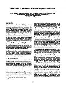
3. NetServ NetServ is a programmable node architecture designed for deploying in-network services [14]. It is suited for any types of nodes, such as routers, set-top boxes, and user equipment. NetServ includes an in-network virtualized service container and a common execution environment for both network services and traditional addressable services (e.g. a Web server). NetServ is thus able to fill the gap between these two types of services that have traditionally been kept separated in the Internet architecture. In this way administrators can be provided with a suitable flexibility to optimize resource exploitation. The NetServ prototype architecture is shown in Figure 1. It is currently based on the Linux operating system. It includes an NSIS-based signaling protocol [15], used for dynamic NetServ node discovery and service modules deployment therein. The NetServ controller coordinates NSIS signaling daemons, service containers, and the node transport layer. It receives control commands from the NSIS signaling daemons, which may trigger installation or removal of both application modules within service containers and filtering rules in the data plane. Each deployed module has a lifetime associated with it. It needs to be refreshed by a specific signaling exchange by its lifetime expiration, otherwise it is automatically removed. The NetServ controller is also in charge of setting up and tearing down service containers, authenticating users, fetching and isolating modules, and managing service policies. Service containers are user space processes. Each container includes a Java Virtual Machine (JVM), executing the OSGi framework for hosting service modules. Each container may handle different service modules, which are OSGi-compliant Java archive files, referred to as bundles. The OSGi framework allows for bundles hot-deployment. Hence, the NetServ controller may install modules in service containers, or remove them, at runtime, without requiring JVM reboot. Each container holds a number of preinstalled modules, which implement essential services. They include system modules, library modules, and wrappers of native system functions. The current NetServ prototype uses Eclipse Equinox OSGi framework. Service modules, represented by circles in Figure 1, are OSGi bundles deployed in a service container. Figure 1 shows two types of modules: • Server modules, circles located within the upper-right service container. They act as standard network servers, communicating with the external through a TCP or UDP port. • Packet processing modules, circles located within the lower-left container. They are deployed in routers along packet path and can both inspect and modify packets in transit. The blue arrow in Figure 1 labeled “forwarded data packets” shows how an incoming packet is routed from the network interface, through the kernel, to a service container process being
executed in user space. The packet is handled by two different modules before being sent back to the kernel and routed towards its final destination. The module classification as server module or packet processing module is only logical, since each NetServ module may act in both ways. This is actually an important NetServ feature since it overcomes the traditional distinction between router and server by sharing each other’s capabilities. The NetServ repository, introduced in the NetServ architecture for management purposes, includes a pool of management programs deployable through NetServ signaling in the NetServ nodes present in the managed network. Currently, the Linux kernel is used to implement the NetServ transport layer. Packet filters, used to intercept packets in the NetServ node, and rules, used to route them to the proper service container, are installed in the node forwarding plane by using the netfilter library through the iptables tool. The next section highlights the NetServ signaling features that enables several functions of the subsequent autonomic management architecture.
NSIS signaling daemons
Modules verification NetServ NSLP UNIX socket
NetServ repository Packet NetServ Controller processing
Modules installation
modules
GIST
GIST packet interception
Java OSGi
iptables command Netfilter
Service Container
NFQUEUE #1
Linux kernel transport layer
Server modules
Java OSGi Service Container
Client-server data packets
Forwarded data packets Signaling packets
Figure 1 – NetServ node internal architecture.
3.1.
NetServ Signaling
NetServ dynamic node discovery and dynamic module deployment are capabilities enabled by the NSIS-based signaling protocol. NSIS (Next Steps In Signaling) [15], is an IETF standardized protocol suite for signaling which consists of two layers: • •
NSIS transport layer protocol (NTLP), used for sending messages, which is regarded as independent of any signaling application; NSIS signaling layer protocol (NSLP), which defines message format and sequences; it contains the signaling application logic.
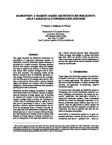
These NSIS signaling layers are part of the NetServ architecture. They are represented in Figure 1 by two boxes, labeled as “GIST” and “NetServ NSLP”. GIST (General Internet Signaling Transport protocol), is a widely used implementation of NTLP. NetServ NSLP is the NetServ-specific implementation of NSLP. These two layers run as separate daemon processes in each NetServ node and exchange messages and events through UNIX sockets. The current implementation of the NetServ signaling daemons is based on an extended version of NSIS-ka, an open source NSIS implementation by the Karlsruhe Institute of Technology, modified so as to provide the dynamic capabilities needed by NetServ. The current GIST specification defines the on-path discovery method only, which is currently used in NetServ. Nevertheless the standard allows introducing different message routing methods and provides generic objects for making GIST easily extendable. For example, an epidemic routing method would allow discovering and signaling peers in all directions efficiently. In what follows, the default routing method is on-path. The red arrow, in Figure 1, indicates the path of a signaling packet within a NetServ router, while Figure 2 shows a typical NetServ NSIS message exchange in a network including both NetServ and non-NetServ nodes. In a generic message exchange a GIST query packet is first sent through the network towards a specific destination, from the NetServ Initiator (NI), in order to discover, if any, on-path NetServ nodes; the query is then intercepted by the GIST daemon of the first NetServ node on-path (NetServ Forwarder - NF) which begins the association process by sending back a response message; the association handshake is then completed by the NI by issuing a confirm message. Once the peer association is completed, the NI sends the NetServ NSLP signaling message directly to the NF GIST daemon, which passes it to the NetServ NSLP layer, which first unpacks the signaling packet and then send it to the NetServ controller. The controller acts on the message by issuing commands to the appropriate service containers. Upon receiving the signaling packet, if the initial destination has not been reached, the discovery process continues towards the NetServ Receiver (NR) by the same message exchange. If a non-NetServ node on-path receives a GIST query, it simply forwards it transparently to the next hop according to its routing table as a normal IP packet (see Figure 2). Note that after a peer association is established, subsequent signaling messages are directly transmitted to the peer without involving any another discovery process, thus speeding up delivery of signaling messages. NetServ signaling messages convey commands to install and remove modules, and to retrieve information about NetServ nodes. Any authorized NetServ instance can query any other NetServ node to discover, for example, the supported types of services, the list of the currently installed modules, a particular service output, and general information about the node and its supported service policies and containers. Two kinds of NetServ signaling messages are used, requests and responses, and three types of NetServ requests, SETUP, REMOVE, and PROBE. The SETUP message is used to install a module on the NetServ nodes on-path and to refresh the lifetime of currently installed modules thus avoiding their expiration. The REMOVE message is used to force removal of a module. The PROBE message is used to obtain the status of NetServ nodes, their capabilities, and policies. Each request has a corresponding response. Responses to SETUP and REMOVE requests simply acknowledge the message reception and, eventually, the last node on-path. A response message to a PROBE request carries the probed information. As the message flows downstream, each node adds its own information to the probe response stack in the message. The full response stack is then delivered back to the NI. Figure 2 shows a SETUP and PROBE message exchange including the response stack creation and delivery. The REMOVE exchange is similar to the SETUP one, and is not shown for simplicity.
NI
NF
IP Router
IP
IP
GIST Query (UDP) GIST Response (UDP) GIST Confirm (TCP)
GIST discovery and association completed
Setup Request (TCP)
NR IP
GIST Query (UDP) GIST Response (UDP) GIST Confirm (TCP) Last-node detection (Timeout, ICMP check)
Setup Request (TCP) Setup Response (TCP)
Setup Response (TCP)
GIST Query (UDP) GIST Response (UDP) GIST Confirm (TCP)
GIST discovery and association completed
Probe Request (TCP)
GIST Query (UDP) GIST Response (UDP) GIST Confirm (TCP) Last-node detection (Timeout, ICMP check)
Probe Request (TCP) Probe Response (TCP) Probe Response (TCP)
Probe stack
Probe stack Probe #1
Probe #2 Probe #1
Figure 2 – NetServ signaling flow.
3.2.
Management Architecture
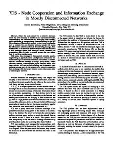
The deployment, maintenance, and control traffic generated by a widespread disseminations of management agents over a variety of heterogeneous nodes may require a huge effort. A static management architecture, although autonomic, is not suited for such a pervasive network. Clearly, not all devices with a network interface can host a management agent, even with simple monitoring tasks. On the other hand, no devices should be excluded from the deployment of a management strategy. A possible solution consists of providing a management architecture with discovery capabilities and hot-deployable components so as to tune the instantiation of the management programs where they are actually needed. This way a suitable balance between costs and benefits is achievable, which may be different for any management objective. In what follows we describe an autonomic management architecture implementing the functions needed in a Future Internet scenario. Figure 3 shows the basic element of the proposed architecture, the NetServ Autonomic Management Element (NAME). It is inspired by the FOCALE architecture shown in [5], which has been mapped into the service deployment architecture shown in Figure 1. This decision follows from the consideration that the FOCALE architecture already includes most of enabling mechanisms for autonomic network management and its modularity allows integrating the unique features of NetServ that, we believe, may introduce significant dynamics in network and service management. The NetServ additional functions are included in this architecture by implementing it as a NetServ service, and by also introducing the PEP (policy enforcement point) deployment module, which can deploy management programs over the selected NetServ managed resources at runtime. These programs are stored in the NetServ repository.
Management actions are context aware. Context consists of the whole set of information characterizing customer services, network services, link quality, user preferences, operator agreements, and anything else deemed significant for management purposes. Context related information are received from external collectors, which may be heterogeneous. In order to use all of them together, they need to represented by a common syntax. This task is done by the Modelbased translation layer (MBTL), which maps the vendor specific information into the information model. This representation is carried out by using models stored in the object models repository shown in Figure 3. The information received from external is then processed by the Policy analyser and PDP (PAPDP). If the PA-PDP receives a context-related information that cannot be associated with any context model already known, this information is passed to the set of modules that have to process it in order to define the needed actions and the relevant policies for keeping the context within an acceptable state. These modules are the Semanting reasoning engine (SRE), the Action planner (AP), the Action Manager (AMG),and the Feedback controller (FC). Their functions are inherited form the FOCALE architecture. In particular, the information related to the unknown context is first processed by SRE, which uses ontologies, stored in the relevant repository, for inferring the system state. If this state needs controlling actions, the AP identifies them. The set of actions deemed necessary for leading the system to an acceptable state are passed to the AMG, which has to organize them according to a specific strategy, including action compatibility check and schedule. This strategy is passed to the PA-PDP, which can trigger its realization. After that, the FC is in charge of monitoring the outcomes of the selected strategy. If it proves successful, it is encoded in a set of policies which are added to the relevant repository. The set of active policies are used by the PA-PDP to keep the system state acceptable, even by deploying the management programs available in the NetServ repository. The introduction of some NetServ specific functions has an impact on all the entities of the architecture, since they are mapped into the system ontologies, are present in the relevant semantic reasoning algorithms, contribute to the set of active policies deployed, and affect the relevant management decisions. It is worth noting that this architecture is backward compatible. The legacy resourced management can co-exist with the dynamic NetServ management. In addition, as shown in [5], this type of architecture is easily replicable so as to form a NAME domain, which is in turn replicable in a fractal fashion. This way, system management may be organized hierarchically, with outer control loops implementing orchestration functions and inner loops having specific device management tasks. In addition, the NAME implementation as a NetServ service allows it to achieve a further attractive property. According to the system needs, such as the fulfillment of some policies or due to the need of migrating services, a NAME can either replicate itself or move to any NetServ node of the network. Again, even the individual NAME modules may easily be moved from a hosting machine while remaining associated with the logical NAME architecture. In synthesis, the NAME deployment in NetServ makes it straightforward to implement autonomic management functions governing the management architecture itself, which is a further self-management level with respect to traditional systems.
NetServ Autonomic Management Element
Action manager
Semanting reasoning engine
Feedback controller
Action planner PEP module deployment
Policy analyzer and PDP Neutral data/commands
Object models System ontology System policies NetServ repository
NetServ Autonomic Manager
Netserv commands
DEN-ng information model
Model-based translation layer Specific data and commands
NetServ managed resource(s)
Managed resource(s) Figure 3 - Management Architecture
4. Case study: self-protecting from a DoS Attack This section describes an experiment showing the NAME effectiveness in self-protecting a network resource from a DoS attack, one of the most important Internet security threats [17]. The attack shown in this experiment is just a sample of generic DoS attack, but it is sufficiently structured to show the NetServ dynamic properties brought to the management architecture. Figure 4 shows the network topology in this experiment, which we have implemented in the well-known GENI (Global Environment for Network Innovation, [16]) experimental platform. The victim, an application server, is protected by a NAME instance. The attack is a classic DoS flooding attack, performed by a number of hosts in different networks [17]. A lightweight NetServ service module, called Rate_Monitor, is executed in the NAME itself and evaluates the rate of incoming traffic and notifies the PA-PDP NAME module (see Figure 3). When the attack starts (see Figure 5 at time t1), the local Rate_Monitor notifies the NAME engine the value of the incoming rate above the alarm threshold. This information reveals that the network has entered an unacceptable state. The set of actions deemed necessary for leading the system to an acceptable state are: -
retrieval of a Rate_Limiter module from the NetServ repository and its deployment on the local interface, in order to protect the victim against the overwhelming service requests;
-
deployment of a number of Rate_Monitor modules in the NetServ nodes all around the NAME instance, so as to identify the incoming attack directions and deploy additional Rate_limiter modules on nodes where the observed value of the incoming service requests are above a given threshold. Attack sources
1st replication
1° remote Rate_Limiter 2° remote Rate_Limiter 3° remote Rate_Limiter
2nd attack
1st attack
N1
N3
N2
Monitor dissemination process
N A M E Victim
3rd attack
Attack sources 2nd replication
Attack sources
Figure 4 - Network topology for our DoS experiment on GENI.
The objective of the second action is twofold. First, any attack direction can be identified and the attack can be faced upstream. Second, in this way we relieve the network from the traffic generated by the attackers (denial of network service). In order to execute the second action, the NAME instance starts sending NetServ PROBE messages towards all directions from itself up to three IP hops1, so as to identify the NetServ nodes able to host and execute an instance of the Rate_Monitor module (see Figure 5). Then, by using the NetServ deployment signaling, the NAME engine deploys a Rate_Monitor module on the selected nodes, which immediately start reporting incoming rate values. Note that in this phase the application server is protected by the Rate_Limiter instance executed by the NAME itself. On the basis of reported values, which are the portion of interest of the new context, the Action Planner of the NAME identifies the node N1 shown in Figure 5 as the best candidate to deploy a remote Rate_Limiter module, since it is the most distant node (in terms of IP hops) from the NAME with an incoming rate above the alarm threshold. Thus, by using the NetServ signaling, the NAME can instantiate the Rate_Limiter in N1. The Rate_Limiter module interacts with the NAME, which receives reports of all deployed Rate_Monitor modules, and changes the acceptable incoming rate threshold dynamically, depending on the number and frequency of detected requests. In this way, a further control loop is created so that each management action enforced by the NAME is dynamically adapted to possible context and state changes. 1
This value may be changed according to network topology and management purposes.
Attacker
N1
Attacker
N2
Attacker
N3 NAME
t1
Attack detection time ΔT
Victim
Rate_Limiter deployed on NAME NetServ signaling Probe messages Rate_Monitor deployed on N1 N2 N3 Rate_Monitor reports Rate_Limiter deployed on N1
t2
Attack Control
ΔT
Rate_Monitor report: attack detected Rate_Limiter deployed on N2 t3
ΔT
Rate_Monitor report: attack detected Rate_Limiter deployed on N3
Figure 5 – Signaling flow in the GENI experiment.
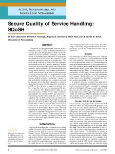
The runtime effects of this control action can be observed in Figure 6. Four charts, showing the normalized incoming rate vs. time, are shown. The incoming traffic rate is normalized to the target rate supported by the victim of the attack. It is advertised by the NAME to the Rate_Limiter modules. In the first three charts the ingress and egress rate of each NetServ router in the network (N1, N2, N3 in Figure 5) are shown. The ingress interface is the one receiving the aggregate malicious traffic, and the egress interface is the one transmitting the unblocked portion of such traffic towards the victim. The fourth chart shows the aggregate incoming rate generated during the three attacks and the incoming rate at the NAME interface. When, at time t1 (around t=28.5s in Figure 6) the attack begins, the set of management actions identified by the NAME is executed and the rate of incoming service request traffic to the NAME module is throttled to a tolerable value. The effectiveness of the Rate_Limiter module is shown in Figure 6, in which the egress rate of N1 and the NAME ingress rate start fluctuating around the target rate. In any case, the NAME Rate_Limiter module is still running, just to protect the server in case of additional sources of attack. All monitor modules are managed by soft states, with configurable lifetime. Thus, they are automatically removed if not refreshed by the NAME by their lifetime. This allows simplifying their management. In particular, the deployed Rate_Monitor modules which do not report alarming values can be simply left unrefreshed, and the relevant node resources are released upon lifetime expiration. In the PEP module, the notification interval and the allowed rate of incoming service requests can be adapted to measured values, by applying the policies communicated by the PA-PDP module on deployment. At time t2 (t=46s in Figure 6), the attacker adds additional sources of DoS packets in other networks, thus bypassing the deployed shield. Nevertheless, since the NAME instance has been executing the monitor and rate limiter module since attack beginning, it can both protect the server and argue that the previous remote counteracting action has been bypassed. If the previously deployed Rate_Monitor modules are still active, some of them start reporting values of the observed incoming rate beyond acceptable values. This context information allows the NAME to identify the NetServ node N2 as the best candidate to deploy another remote instance of the Rate_Limiter
module. If the lifetime of the previously deployed Rate_Monitor modules has expired, they are redeployed. Again, Figure 6 shows that after the latter shield deployment, the incoming rate at the NAME ingress interface and at the N2 egress interface rate has been decreased to acceptable values. Finally, the attacker starts a further attack session from another network at time t3 (t=65.5s in Figure 6). The self-protecting procedure is repeated again, thus deploying a further instance of the Rate_Limiter on N3 that decreases the service request rate once again to a value as close as possible to the target value. When the attack ends, all the monitor and rate limiter instances are no longer refreshed. Hence, they are automatically removed, without any additional signaling. In order to actually estimate the end of attack condition at the NAME, the remote monitor modules track both forwarded and dropped service requests, and report back the relevant statistics. From the network traffic charts shown in Figure 6 it is also possible to extract the threat detection and module deployment time for the DoS attack by the NAME node. When the first attack comes at t=t1 the total time taken by the NAME to (i) deploy a local Rate_Limiter, (ii) discovery the surrounding NetServ nodes, (iii) deploy Rate_Monitor modules on all capable NetServ nodes, (iv) identify the node closest to the source of attack and (v) install the Rate_Limiter module on it, is about 2s. When the second and the third attacks come, respectively at t=t2 and t=t3, the reaction time of the system decreases to around 1s since the Rate_Monitor modules are still active and no node discovery and Rate_monitor installation are needed. Only the attack detection, the identification of the node closest to the source of attack, and the Rate_Limiter deployment by the NAME Action Planner are executed. Clearly, this experiment is not an exhaustive analysis of attack, monitor, and control actions. Our aim was to highlight the potentials of NetServ in providing an effective platform for the autonomic management of the Future Internet. Normalized rate
6 4
N1 ingress interface N1 egress interface
t1
2 0
0
10
20
30
40 Time [s]
50
60
70
80
50
60
70
80
70
80
70
80
Normalized rate
6 N2 ingress interface N2 egress interface
4
t1
t2
2 0
0
10
20
30
40 Time [s]
Normalized rate
6 4
t1
N3 ingress interface N3 egress interface
t3
t2
2 0
0
10
20
30
40 Time [s]
50
60
Normalized rate
6 Attacker 1 Attacker 2 Attacker 3 NAME ingress interface
4 2 0
0
10
20
t3
t2 t1
30
40 Time [s]
50
Figure 6 – Runtime behavior of network traffic.
60
5. Conclusion This paper shows how the NetServ platform can be used for implementing autonomic management architectures for the Future Internet. The proposed management architecture, which is an extension of the well known FOCALE framework, fully exploits the NetServ dynamic properties, which translates in the capabilities of automatically deploying, configuring, and removing at runtime both PDP and PEP modules on network nodes, in order to provide network management with effective autonomic capabilities. In fact, the usage of programmable nodes able to host any service, made up by combining inferential, decisional, monitoring, and actuator modules, represents a powerful instruments to implement autonomic network management functions. In order to show the effectiveness of the proposed solution, we have presented a case study which highlights how NetServ allows deploying self-protecting network functions. In the experiment, carried out on the GENI testbed, we show how the proposed architecture is able to counteract a DoS attack by selectively deploying monitoring and actuator modules at runtime. Finally, it is worth noting that the proposed solution is only an example of the potential of the NetServ platform, since any autonomic management architecture can be deployed as a service in NetServ.
References [1]
I.F. Akyildiz, et al., “The state of the art in interplanetary Internet”, IEEE Communications Magazine, 42(7), 2004, pp. 108-118.
[2]
Van Jacobson et al. “Networking Named Content”, CoNEXT 2009, December 2009, Rome, Italy.
[3]
K. Park, “The Internet as a complex system”, K. Park and W. Willinger, Editors, The Internet as a Large-Scale Complex System, Oxford University Press, 2005.
[4]
N. Blum et al., “Towards Standardized and Automated Fault Management and Service Provisioning for NGNs”, Journal of Network and System Management, 16(1), 2008, pp. 63– 91.
[5]
B. Jennings et al., “Towards Autonomic Management of Communications Networks”, IEEE Communications Magazine, Vol. 45, Issue10, Oct. 2007.
[6]
N. Agoulmine e al., “Challenges for Autonomic Network Management”, MACE 2006, October 2006, Dublin, Ireland.
[7]
J. O. Kephart, D. M. Chess, “The Vision of Autonomic Computing”, IEEE Computer Magazine, 36(1), 2003.
[8]
J. Strassner et al. “The Design of a New Policy Model to Support Ontology-Driven Reasoning for Autonomic Networking”, Journal of Network and Systems Management, 17(1-2), 2009.
[9]
L. Cheng, et al., “Self-organising Management Overlays for Future InternetServices”, MACE 2008, September 2008, Samos Island, Greece.
[10] B. Mathieu et al., “Self-Management of Context-Aware Overlay Ambient Networks”, IFIP/IEEE IM 2007, Munich, Germany, May 2007. [11] S. Balasubramaniam et al., “BiRSM: bio-inspired resource self-management for all IPnetworks”, IEEE Network, 24(3), 2010, pp. 20-25. [12] S.S. Kim et al., “Towards Management of the Future Internet”, IFIP/IEEE IM 2009, Long Island, NY, USA, June 2009.
[13] H. Ballani, C. Francis, “CONMan: taking the complexity out of network management”, INM’06 workshop, Pisa, Italy, September 2006. [14] J.W. Lee et al, “NetServ: Active Networking 2.0”, accepted for publication in FutureNet IV 2011, available for reviewers at http://conan.diei.unipg.it/pub/futurenet-iv.pdf [15] X. Fu et al., “NSIS: a new extensible IP signaling protocol suite”, IEEE Communications Magazine, 43(10), 2005, pp. 133- 141. [16] The Global Environment for Network Innovations (GENI) project, http://www.geni.net. [17] X. Yang, X. Liu, Y. Xia, “NetFence: Preventing Internet Denial of Service from Inside Out”, ACM SIGCOMM 2010, Delhi, India.