11
An Environment and Algorithm for FMS Controller Testingt Z.Deng Narvik Institute o/Technology Teknologiveien 10,8501 Narvik, Norway Tel: 47-769-22181 Fax: 47-769-44866 E-mail:
[email protected]
Z. Bi and Y. Zhu Division #503 Nanjing University 0/ Science and Technology Nanjing 210094, P. R. China Fax: 86-25-4431622 Tel: 86-25-4315615
Abstract
The authors have developed a physical environment for testing controllers of Flexible Manufacturing Systems (FMS). In this paper, firstly, the testing mechanism is discussed. Secondly, the architecture of the testing environment is illustrated. Finally, an algorithm based on a model built for testing the correctness of the series of control commands from a tested FMS controller is given. A modelling methodology called Structured Macro Petri Net (SMPN) conceived by authors is described briefly.
Keywords Software engineering, flexible manufacturing system (FMS), control engineering, software testing, system modelling, Petri net (PN), structured macro Petri net (SMPN)
t
This work is supported with the pre-research foundation by Science and Industry Committee of China.
A. Storr et al. (eds.), Software Engineering for Manufacturing Systems © Springer Science+Business Media Dordrecht 1996
124
1
Software Engineering for Manufacturing Systems
INTRODUCTION
For many manufacturers of consumer goods, flexible manufacturing and assembly is the only way in which they can efficiently compete in the market-place with a range of product variants. This is because clients are increasingly looking for products tailored to their own needs rather than mass-produced products (Rembold, 1993). Therefore, for producing such product variants, flexible manufacturing systems (FMS) are required. Flexible manufacturing systems typically consist of (Deng, 1989): • several manufacturing equipment (machines) such as CNC machining centres, CNC measuring machines, washing machines, etc.; • part transport and handling equipment such as automatic guided vehicle (AGY) together with part loading and unloading stations, central part buffers, and local part buffers dedicated to an individual manufacturing machine to carry out efficient part-jlow (or called job-flow) tasks within the FMS system; • tool transport and exchange equipment such as movable robots together with tool loading and unloading stations, central tool base, and local tool magazines for each manufacturing machine to carry out efficient tool-jlow within the FMS system. All actions that happen among the part-flow procedure or the tool-flow procedure in an FMS are controlled by the FMS controller. In other words, the FMS controlIer makes a series of decisions and issues a series of commands to control the part-flow and/or the tool-flow in a series of time moments. Since the early 1980s, there have been more and more FMSs installed in enterprises, and a number of FMS controlIers developed by various developers. It seems that there exists a growing tendency of installing FMSs and developing various controllers for those FMSs. As is well known, developing an FMS controller involves a complicated task in hardware and software development. Especially in the software development, if many bugs exist in the package, probably it may cause a disastrous result while the FMS is running. Therefore, the authors have launched a project since 1991 to develop a testing environment for testing the FMS controlIers which may be developed by various developers. In other words, the authors wanted to create a testing centre where any developer or client of an FMS controller can ask the testing centre for the testing and/or debugging of his/her FMS controller. Meanwhile, if someone is willing to develop an FMS controller before his/her physical FMS system installation, he/she may also make use of the facilities of this testing centre to develop his/her FMS controller. It also means that we have to create a virtual equipment environment where the FMS configuration composed of CNC machines, part-flow sub-system, tool-flow subsystem, etc., can be configured for folIowing purposes (Deng, 1995): • receiving the sequence of control commands from an FMS controlIer being tested; • executing the control commands; • replying with a normal message to inform the FMS controlIer that a control command is executed properly or; • replying with a abnormal message in random mode to inform the FMS controlIer that certain malfunction is happening in the facilities.
125
An environment and algorithm for FMS controller testing
After years' work, the first stage of the testing environment is accomplished. In what follows in this paper, we will describe: (1) the mechanism of FMS controller testing, (2) the architecture of the testing environment, (3) the model and algorithm for testing real-time control function of a tested FMS controller, and (4) macro structurisation of places and resources.
2 MECHANISM OF FMS CONTROLLER TESTING Generally, software production broadly follows the phases: requirements, specifications, design, implementation, integration, maintenance, and finally, retirement (Schach, 1990). After finishing the development of each of the first three phases, verification is required. After each of both the implementation phase and the integration phase, testing is required to assure the quality of that phase's solution. During the implementation phase's testing, the modules are tested. During the integration phase's testing, there are three types of testing required, namely integration testing, product testing, and acceptance testing (Schach, 1990). The purpose of integration testing is to check that the modules are combined together correctly to achieve a software product that satisfies its specifications. When the integration testing has been completed, product testing is performed. The functionality of the product as a whole is checked against the specifications. The final aspect is acceptance testing. Here the client enter the picture. The software is delivered to the client, who tests the software.
. FMS Input (i)
Tested FMS
Output (0)
controller (functionality P)
configura-
feedback data
tion data • Control command
• Copying feedback data to
P=f(i.o)
TEST_SYS
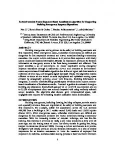
Figure 1 Black-box testing for an FMS controller.
Figure 2 testing.
Testing principle of FMS controller's
As mentioned above in the introduction, our desire is to create a testing environment where developers of various FMS controllers can ask the testing environment for the testing of hislher FMS controller. Because a wide variety of FMS controllers are developed outside the testing environment, and the developments are carried out by various groups other than the
Software Engineering for Manufacturing Systems
126
group working in the testing environment, it is not usually possible for the group who works in testing environment to understand the internal software structure of the various tested FMS controllers. That is to say, our work is only involved in product testing and/or acceptance testing if a client wants to use the environment for his/her acceptance testing. Therefore, the mechanism conceived for FMS controllers' testing in our environment is limitedly to the testing of functionality which is specified in the specifications. In other words, the testing environment copes with a tested FMS controller as a black-box as shown in Figure I. Considering the relationship between the tested FMS controller and the testing system in our environment, the testing principle can be expressed and depicted as shown in Figure 2 where the testing system is composed of: • a test-executing sub-system (or called TEST_SYS for brevity); • an FMS configuration and emulation sub-system (or called STUB for brevity). Initially, one should make use of the STUB (see lower part of Figure 2) to configure the FMS facilities, part-flow system, and tool-flow system which will be controlled by the tested FMS controller. The FMS configuration data created is then transferred to the TEST_SYS where the FMS configuration data is stored in the database and is ready for use by the TEST_SYS. According to both the functional specifications of the tested FMS controller and the stored FMS configuration data, the TEST_SYS creates various testing-case data (see upper part of Figure 2) to drive the tested FMS controller. The content of the testing-case data includes the production data or, say, the job assignment which consists of the sets of data included in Tables I through 4. Table 1 Job assIgnment Priority of job Due date No. of job
Type of part
No. of blank
Batch quantity
No. of process plan
.J Table 2 Process Ian No. of No. of
Table3
No. of
0 No. of NC ro ram
uirement No. of NC ro ram No. of tool
Duration of 0
Tool life
127
An environment and algorithm for FMS controller testing
The FMS controller being tested starts to issue its first control command to the STUB according to the testing-case data. Meanwhile, the STUB emulates the execution of the control command, copies the control command to the TEST_SYS, transmits to the tested FMS controller either a normal feedback data, or an abnormal feedback data, and copies as well the feedback data to the TEST_SYS. From the second command on, the FMS controller issues its control commands according to not only the testing-case data, but also the feedback data.
3 ARCHITECTURE OF TESTING ENVIRONMENT Creation of a testing environment involves architectural consideration concerning both the hardware environment and the software environment. The architectural consideration for the hardware environment should address the requirement for serving various sources of FMS controllers which may reside on various types of computers such as Sun workstations, VAX workstations, SGI workstations, HP workstations, and PC computers. Therefore, we have used the hardware configuration as shown in Figure 3.
VAX4000/60
VAX4000/60
workstation
wor1