NASA Goddard Space Flight Center, Greenbelt, MD 20771 ... This closed-loop, hardware inclusive simulation capability ... incoming data, calls the navigation process, and uses the navigation results as input to the formation control process.
--
An Environment for Hardware-in-the-Loop Formation Navbation and Control ----
R. Burns' and B. Naasz.+ NASA Goddard Space Flight Center, Greenbelt, MD 20771 D. Gaylor: and J. Higinbotham$ Emergent Space Technologies, Inc., Greenbelt, MD 20770
Recent interest in formation flying satellite systems has spurred a considerable amount of research in the relative navigation and control of satellites. Development in this area has included new estimation and control algorithms as well as sensor and actuator development specifically geared toward the relative control problem. This paper describes a simnlation facility, the Formation Flying Test Bed (FFTB) a t NASA Goddard Space Flight Center, which allows engineers to test new algorithms for the formation flying problem with relevant GN&C hardware in a closed loop simulation. The FFTB currently supports the inclnsion of GPS receiver hardware in the simulation loop. Support for satellite crosslink ranging technology is at a prototype stage. This closed-loop, hardware inclusive simulation capability permits testing of navigation and control software in the presence of the actual hardware with which the algorithms must interact. This capability provides the navigation or control developer with a perspective on how the algorithms perform as part of the closed-loop system. In this paper, the overall design and evolution of the FFTB a r e presented. Each component of the FFTB is then described. Interfaces between the components of the FFTB are shown and the interfaces to and between navigation and control software are described. Finally, an example of closed-loop formation control with GPS receivers in the loop is presented.
I.
Introduction
S
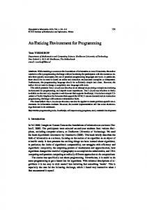
atellite formation flying systems have attracted much attention in recent years due to potential advantages over traditional, monolithic satellites. These advantages include increased effective aperture of on-orbit observing systems, capability to distinguish between spatial and temporal variations of in-situ measurements of the space environment, graceful degradation of the system as a result of spacecraft failures, system reconfiguration via a change in formation, phased formation population, and economies of scale in the construction of spacecraft. In fact, the President's Commission on Implementation of United States Space Exploration Policy recently identified formation flying as one of seventeen enabling technologies for attainment of exploration objectives [ 13. NASA has several formation flying systems in its plan for upcoming missions including the Micro-Arcsecond Xray Imaging Mission [2], Stellar Imager [3], Terrestrial Planet Finder [4], Submillimeter Probe of the Evolution of Cosmic Structure [ 5 ] , Constellation-X [ 6 ] ,and Magnetospheric MultiScale Mission [7]. Additionally, one of the five concepts that the New Millennium Program is considering for the technology demonstration mission ST-9 [8] is a precision formation flying mission. Among the most challenging aspects of these missions is the relative navigation and control of spacecraft within a formation. Many researchers have developed novel concepts and algorithms for formation navigation and control over the past few years. The aim of the FFTB, shown in Figure 1, is to provide an environment where these new
*
'
Engineer, Code 591, AIAA Member. Engineer, Code 595, AIAA Member. Engineer, AIAA Member. Engineer. 1
American Institute of Aeronautics and Astronautics
algorithms can be tested in the presence of real hardware and where hardware can be tested against the unique challenges of formation flying requirements. Major benefits of this type of testing include the exercise of hardwaresoftware interfaces, early identification of hardware problems, and realistic assessment of algorithm performance in the presence of actual hardware error characteristics.
Figure 1. The Formation Flying Test Bed
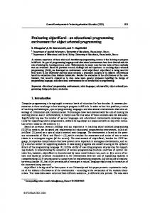
II. FFTB Architecture The FFTB hardware architecture [9] is shown in Figure 2. The simulation originates at the Environment Computer, which generates vehicle trajectories via high fidelity orbit propagation for each spacecraft in formation. The trajectories generated by the Environment are used as truth for the simulation. The Environment Computer then supplies ephemeris information to the Spirent system in real-time by monitoring a one pulse-per-second (PPS) signal originating from the GPS Simulator as shown or an external source such as a cesium oscillator. The GPS Simulator uses that information together with almanac data from the GPS constellation and the receivers' antenna configurations to produce up to four Radio Frequency (RF) signals representative of the aggregate signals from the visible portion of the GPS constellation (up to 16 GPS satellites per RF signal) for each GPS receiver in the formation. Those RF signals are routed via coaxial cable into the GPS receiver hardware where measurements are generated and sent via RS-232 interface (serial) to the Flight Computers. The Flight Computers host the navigation and control processes under the management of a top level process called the Flight Executive that manages incoming data, calls the navigation process, and uses the navigation results as input to the formation control process. The Flight Executive then feeds the maneuver commands from the control process back to the Environment Computer for incorporation into the equations of motion, thus closing the control loop. The Crosslink Channel Simulator (CCS), a current development at the prototype stage [lo], is also shown in Figure 2. As shown, the CCS will enable insertion of satellite crosslinks in the simulation loop. The CCS is the analog to the GPS Simulator for crosslink hardware. That is, on the basis of spacecraft trajectory information received from the Environment Computer, it modifies inter-spacecraft RF transmissions, introducing appropriate levels of time delay, Doppler frequency shift, and signal attenuation, thus enabling realistic simulation of inter-spacecraft communication and ranging. Both the Flight Computer and the Environment supply information to the Visualization Computer for data plotting and near real-time, three-dimensional animation of the formation through Satellite Tool Kit (STKTM).
III.
FFTB Elements
A. Environment Computer The Environment Computer is a standard personal computer running the Linux operating system. A kernel device driver listens to the incoming PPS in order to synchronize the simulation with the GPS Simulator. The
2 American Institute of Aeronautics and Astronautics
,
spacecraft orbits are propagated in real-time using the Spacecraft Trajectory and Attitude Real-time Simulation (STARS). STARS currently uses the orbit propagation capability resident in the GPS Enhanced Onboard Navigation System (GEONS) [ 1I], and the attitude profile is prescribed as Earth-pointing. State updates are sent to the GPS GPS Sirnulam F
!
I
RF
GPSRecemr
_I
FIigM Computer
Cmsslink
Sirnulalor
GPS Recener
snneni m4m
f
EllQhlComputer
Cmsslink
Figure 2. FFTB Hardware Architecture Simulator at 10 Hz;consequently, the orbit propagation step size is 0.1 s. In the future the step size will be increased in order to avoid long-term numerical error accumulation, and intermediate state updates will be calculated using an interpolation scheme. STARS has the capability to accept control maneuvers over UDP (Universal Datagram Protocol) Socket connection fiom the Flight Computer. The maneuver messages are currently sent as AV (instantaneous change in velocity) values in the Radial, Transverse, Orbit-Normal (RTN) fkme of the spacecraft where radial is the unit vector of the position vector, transverse is perpendicular to the position vector in the orbit plane and in the same sense as the velocity vector, and orbit normal completes the right handed triad. The AV message is converted to a constant acceleration zpplied over the integration step.
1
B. GPS Simulator
The GPS Simulator is a Spirent STR4760 (Figure 3) with four available RF outputs which can accommodate up to four GPS receivers with one antenna each. The antenna pattern for each receiver is configurable; normal FFTB procedure is to assign hemispherical coverage. The GPS Simulator can simulate several sources of GPS measurement error including ionospheric delays, multipath, and Selective Availability. Up to sixteen GPS satellite signals are generated simultaneously on each RF output; default selection of the simulated GPS signals is by elevation angle but can be configured to use signal strength which is useful for spacecraft in orbits which go above the GPS constellation.
Figure 3- SPirent 4760 GPS Simulator
C. GPS Receivers The FFTB currently has an inventory of several space-capable GPS receivers. Four GSFC-developed PiVoT receivers [ 121 are available and are currently being updated for above-the-constellation use. Two Orion receivers from the German Space Operations Center are also available and include a useful relative navigation function
3 American Institute of Aeronautics and Astronautics
whereby they share GPS measurements via direct RS-232 connection and the relative satellite state is estimated. A commercial off-the-shelf receiver, the Ashtech G-12 [131, is also available for performance baselining.
D. Flight Computers The Flight Computers host the navigation software process and formation controller as shown in Figure 4. The formation controller is a modular component that can accommodate either MATLABm scripts or standard C/C+ code. As mentioned previously, the crosslink interface is not yet implemented, but, with the delivery of the operational CCS, it is expected to be in place before February 2005. In lieu of crosslink hardware in the simulation, the Flight Executive is capable of passing inter-spacecraft data messages to the other Flight Computers via UDP sockets. The Flight Executive is a process that sits on top of the navigation and control functions and is responsible for data management and execution of the navigation and control functions.
Figure 4. Flight Executive Schematic
E. Visualization Computer The Visualization Computer receives the truth data from the Environment Computer and navigation results from the Flight Computers, both via UDP socket connection. Truth data are then passed to STKm for animation (Figure 5) of the formation. The Visualization Computer also has a near-real-time plotting capability which provides easy access to important information like the number of GPS satellites tracked, navigation errors, etc. F. Crosslink Channel Simulator The CCS will enable FFTB users to insert crosslink hardware in the simulation for more realistic inter-spacecraft communication and ranging. It currently exists in the prototype state as shown in Figure 6 . The capability to introduce signal delay, Doppler shift and attenuation onto a crosslink signal has been demonstrated. Delivery of the operational version of the CCS is expected before February 2005. The operational version of the CCS will introduce signal delay with resolution down to 30 ps at a maximum range of 64,000 km.
W.
Figure 5. STK Visualization
Formation Flying Test Bed Simulator
An all-software, non-realtime simulation has been developed to mimic the performance of FFTB real-time, Figure 6. CCS Prototype hardware-in-the-loop simulation. This simulation, henceforth refered to as FFTESim, is a software version of the FFTB which provides an interface identical to the Flightexec-MatlabTMinterface to allow users to test FFTB guidance and control code in non-real-time. The simulation is driven by the FreeFlyerTMorbit software, and includes high-fidelity gravity, drag, and solar radiation pressure dynamics, as well as measurement noise affecting the estimated states.
4 American Institute of Aeronautics and Astronautics
. ‘
,
V.
Example Result
To demonstrate closed loop control for a formation flying mission, we perform a simulation in the FFTB that inciu&s an aciiyeiy cuIliiolld qilacecrafi aiid a passive ~pacecidfi,each eqiiipgei; with olicifi GPS iecelwi. Absolute orbit determination is performed on the active spacecraft flight computer using the GPS Enhanced Onboard Navigation System (GEONS), which processes pseudorange data from one of the Orion GPS receivers in an Extended Kalman Filter (EKF). For this scenario, GEONS estimates the receiver clock error bias and drift, absolute position and velocity, and drag coefficient. Control accelerations are handled in the EKF by including the accelerations in the state propagation, and by increasing the position and velocity covariance whenever control is applied. Relative navigation is performed by the Orion receivers, which exchange raw measurements over a serial port, and output time and relative position and velocity with respect to the RTN frame of the host satellite. The relative navigation a l g o r i k is described in more detail in [141 and results with a similar configuration of the Orion receiver can be seen in [15]. Control is computed for the active spacecraft using a Matlabm function call commanded by the Flight Executive, which has, as inputs, time, absolute and relative states, and, as outputs, spacecraft control acceleration in the Radial, In-Track, Cross-Track (RIC) h e * * . The control law implemented in this study is a simple proportional-derivative feedback of the difference between the desired trajectory and the relative state information provided by the relative navigation system. Absolute state estimates are not used directly in the control feedback, but are available for computation of coordinate transformations. Thrust is assumed to be equally available in any direction, with magnitude limited to 1OmN. Control is calculated and applied at a frequency of 1Hz. The desired trajectory is circular motion of one spacecraft about the other with a fured separation, and a time varying phase angle within the plane of relative motion of the circular formation. The two spacecraft formation is injected into a nearly circular parking orbit with mean semi-major axis of 6823 km, and mean inclination of 28 degrees. The two spacecraft are separated by a lkm in-plane separation in the parking orbit, with the maneuvering spacecraft trailing. The transfer to the initial precision formation flying configuration is performed using two maneuvers separated by half the orbital period. The first maneuver is a combination radial and out-of-plane burn, which puts the maneuvering spacecraft on course to a point 100 meters ahead of and 100 meters out-of-plane from the passive spacecraft. The second maneuver is a radial burn half an orbital period after the first bum to achieve a natural circular formation. Closed-loop control of the precise circular motion trajectory is simulated in FFTBSim with relative position and velocity noise of Im and 0.5 a d s , and in the FFTB hardware-inthe-loop (HWIL) simulation described above. Table 1. Hardware-in-the-loop steady-state estimation errors for a 4 hour simalation Navigation Type
Position Estimation Error [m]
I GEONS absolute state estimate Orion abs.-state __ est. (maneuvering SIC) Orion abs. State - est (passive slc) Orion relative state estimate --
Mean 1.08 1.29
Velocity Estimation Error [ d s ]
MCX i 2.36 35.93
Mean 0.218 3.058 2.772
8.06
0.510-__ -
Max -
0.494 22.162 40503
2.400
I
Absolute and relative state estimation errors from a 4-hour hardware-in-the-loop FFTB simulation of closed loop formation control are presented in Table 1. The table presents steady-state values from the final 3 hours of the simulation. The GEONS absolute state estimation results are as expected, with position errors on the order of a meter, and velocity efrors on the order of tenths of c d s . The relative state error of the Orion receivers is *I
All relative veiocities described in this paper are assumed to be with respeul to the rotufing referenceJrarne, and therefore include the “omega-cross’’ term.
5 American Institute of Aeronautics and Astronautics
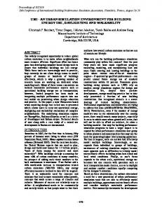
considerably larger than expected. Comparing absolute state errors from the two Orion solutions, we see that the state error is considerably larger for the maneuvering spacecraft than for the passive spacecraft. In hindsight thls result is not surprising. We are seeing the effect of noisy control application on the navigation accuracy. The receiver has no knowledge of the control being applied, and cannot be expected to perform as well in such a perturbed environment. There would be a similar effect in the GEONS output accuracy if the filter had no knowledge of the control acceleration being applied. Table 2 shows controlled inter-spacecraft range errors from both all-software (FFTBSim) and FFTB hardware-inthe-loop (??NIL) simulations. Initial condition errors in this simulation are due to navigation and thrust performance m o r s in the transfer fiom the parking orbit to the desired formation configuration. Figure 7 compares the control performance for the software-only and hardware-in-the-loop simulations. The HWIL mean range error is about 2.5 times worse than the FFTBSim result. This inconsistency is due to a number of effects, including modeling of the state estimation error as white Gaussian noise in FFTBSim, and inconsistent realtime performance in the Flight Executive. Perhaps the most notable data from Table 2 are the thruster duty cycles and total AV values. Thrust is being applied about half as often in the HWIL simulation as in the software-only simulation. Since the Flight Executive software is not synchronized, the control law is not being executed at exactly once per second, resulting in impaired performance.
-,o.
VI. Conclusions The FFTB is a viable and useful tool for assessing the efficacy of formation navigation and control algorithms in the presence of real navigation hardware. Moreover, by effectively exercising hardware-software interfaces and exposing algorithms to real hardware error characteristics, the FFTB serves as the "relevant environment" for Technology Readiness Level advancement.
Table 2 SimulationType
Controlied (Somyare)
115
.-- --
*
95-
9o0
1
,
1
\
\
2 time [SI
..* -
3
Figure 7. Controlled and uncontrolled interspacecraft range, with proportional derivative control targeting lOOm separation
Control performance results Inter-Spacecraft Range Error [cm]
Total AV
Thruster Duty Cycle
Mean
Max
[&SI
E"/.]
FFTBSim
13.24
44.92
1.396
97.0
HWIL
31.14
126.30
0.777
51.8
,
4
References ridge, E.c.,.TI., ei z:., ~ e p o i -oi i iiie PtesiJcriii Cornmissiun on impiemeniaiion o j iinired Srares Space Expioration Policy: A Journey to Inspire, Innovate, and Discover, US. GovernmentPrinting Office, 2004.
White, N., "Micro-ArcsecondX-ray Imaging Mission," http://maxim.esfc.nasa.eov/[cited 29 Jul20041 3
Carpenter, K, "The Stellar Imager Homepage,"httD://hires.esfc.nasa.eov./-si/ [cited 29 Jul20041
4
Jackson, Randal, "TerrestrialPlanet Finder," httD://ulanetsuest.iul.nasa.qov/TPF/tDfindex.html [cited 29 Jul2004I Leisawitz, D., "Submillimeter Probe of the Evolution of Cosmic Structure," httD://sDace.gsfc.nasa.pov/astro/saecs/[cited 29 Jul20043 Mattson, B., "Constellation-X Homepage," httD://constellation.gsfc.nasa.eov/[cited 29 Jul2004I Carson, D., "MagnetosphericMultiScale," httD://sta.esfc.nasa.eov/missions/mms/mms.htm#Conceut [cited 29 Jul2004I
8
"Space Technology 9 Homepage," httD://~~.iul.nasa.eov/st9/index.html [cited 29 Jul20041 Leitner J., "A Hardware-in-the-Loop Testbed for Spacecraft Formation Flying Applications," IEEE Aerospace Conference, V O ~ .2, p ~61 . 5-620,2001.
10
Hunt, C., Smith, C., and Burns, R., "Development of a Crosslink Channel Simulator,'' E E E Aerospace Conference,2004.
'*Goddard Space Flight Center, Mission Engineering and Systems Analysis Division, "GEONS Open ArchitectureSolutions for Onboard Orbit DeteTmination in any Orbit, " httD://eeons.gsfc.nasa.eov/ [cited 30 Jul20043
l2
Wennerstm M, et al, "PiVoT'GPSReceiver, " ION GPS2OOI Conjkrence, 2001.
l3
Haas L, et al, "The Ashtech G12-HDMA: A Low Cost,High Performance GPS Space Receiver," ION GPS 200 Conference, 2000.
l4
Montenbnxk 0,et al. "A Real-Time Kinematic GPS Sensor for Spacecraft Relative Navigatiition, " Aerospace Science and Technology,Vol. 6,43549,2002.
l5
Gill, E., Naasz, B., and Ebinuma, T., "First Results from a Hardware-in-the-LoopDemonstration of Autonomous Formation Flying, " AAS Guidance and Control Conference,AAS 03-040,2003.
7 American Institute of Aeronautics and Astronautics