Specifying Executable Commands: An Example of FAST Domain Engineering David A. Cuka and David M. Weiss Lucent Technologies
[email protected] [email protected] Submitted to IEEE Transactions on Software Engineering
Abstract Software engineers today are often pressured to develop a product so that it can be sold before competing products are ready, but also so that the product is acceptable to their customers. One approach to meeting this pressure is to organize software into families, and to invest in facilities that enable rapid production of family members. We are using a systematic process to define families, design languages for specifying members of families, and quickly develop tools for such languages. The process is known as family-oriented abstraction, specification, and translation (FAST). We have applied FAST to the task of specifying the commands and reports used by technicians to monitor the operation of a telecommunications switch. Such commands, their associated reports, and the accompanying customer documentation form a software family. A key part of the specification for a command or report is the customer documentation for using the command or understanding the report. Our specification language makes the specification of the customer documentation an integral part of the command and report specification. This approach promotes consistency between the software and the customer documentation, makes it easier for developers to write consistent and complete documentation, and allows us to generate the customer documentation from the specification.
1.
Introduction
Software engineers today are often pressured to develop a product so that it can be sold before a competing products are ready, but also so that the product is acceptable to their customers. As the market for consumer software increases, the pressure for rapid production increases. One approach to meeting this pressure is to organize software into families, and to invest in facilities that enable rapid production of family members. We call families where this investment is worthwhile a domain, and we call the process of developing and maintaining the production facilities domain engineering. This paper describes an example of the application of a systematic approach to domain engineering to a common telecommunications domain. In our approach, the investment in domain engineering is realized by the creation of an environment for rapidly producing family members. We expect the result to be a dramatic increase in productivity by the users of the environment. Early estimates of productivity improvements, based on the first version of the environment, are consistent with our expectation.
1
Section 2 of this paper discusses the idea of families and where it is worthwhile to apply the idea. Section 3 describes the commands and reports family, the domain where we have applied a familyoriented production process. Section 4 gives a brief overview of the process, known as FAST, and section 5 describes the key parts of the environment that resulted from our application of FAST to the commands and reports family. Section 6 summarizes the benefits of our approach and section 7 contains our conclusions.
2.
Families
We advocate a family-based strategy for software development in situations where a number of similar programs (will) need to be developed. This idea is not new. Family-oriented software development was suggested by Dijkstra and others in the software engineering literature as early as 1968 [6]. Parnas and others described approaches for building software families in the mid1970s [8], [9]. These approaches are based on the following definition of family. “We consider a set of programs to constitute a family whenever it is worthwhile to study programs from the set by first studying the common properties of the set and then determining the special properties of the individual family members.” -David L. Parnas This definition, taken from [8], is primarily an economic definition, since it depends on the worth of studying the common properties of the programs that form the family. Put another way, the investment in the environment for creating family members is worthwhile if the return from creating the family members is greater than the investment. The return might be in cost savings or in increased income from the ability to produce and sell quickly a greater variety of programs than would otherwise be possible. The family approach works well in situations where there are different versions of a system, (different family members) all of which share common requirements, design, or code. Some examples of such situations are: •
Systems that have the same requirements but must execute on different platforms, (e.g., database management systems or compilers for the same language).
•
Systems that store and use the same data, but vary the processing of the data, (e.g., systems that provide different types of reports based on the same data).
•
Systems that control and monitor the same devices, but have somewhat different behavior, (e.g., telecommunications systems with different features or different billing algorithms).
•
Systems that provide the same interface to the user, but implement their behavior differently, (e.g., different word processors with the same or nearly the same features).
The key new idea in the approach that we use for family-oriented software development is a step that explicitly defines the family and that is the basis for designing a language for specifying family members and creating an environment for analyzing and generating family members. Such languages are often known as application oriented languages, domain oriented languages, or application modeling languages (AMLs). We call such an environment an application engineering environment. From a specification for a family member in an AML we can generate the software 2
for the family member. The addition of a family-definition step to many existing software development processes, such as [5], allows us to have a reasonably systematic process for engineering families. We separate our process into two parts: one part is concerned with defining the family and developing the facilities for producing family members. We call this part domain engineering. The other part is concerned with using the facilities to produce family members. We call this part application engineering. Our process is called family-oriented abstraction, specification, translation (FAST), and is a variation on Synthesis [2].
3.
The Commands and Reports Family
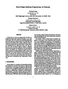
The family that we selected for the project described here is part of the software for a telecommunications switch. Such a switch enables telephone subscribers to place calls to each other, and may be viewed as a large computing system. An example is AT&T’s 5ESS switch, which can handle millions of calls per hour, and whose software contains millions of lines of code. To monitor the operation of the switch and to maintain it, technicians use an interface that allows them to issue commands to the switch and to receive reports on its status. For the purposes or our analysis, we viewed a 5ESS switch as a machine that accepts commands in accordance with CCITT standards, such as [3], takes an action, and produces a report (see Figure 1). Customers must be given documentation that describes the usage of the commands, and the format and meaning of the reports. Our purpose was to give 5ESS software developers a specification language and associated support tools that provide the following capabilities: •
•
A way of specifying for any input command, in one place, the following: -
the syntax of the command, including its name (known as the command code), and the names and types of its parameters,
-
the identity of the program to be used to process the command,
-
various administrative information about the command, such as the name of the data structure used to store information about the command when a technician invokes it,
-
the corresponding terminal acknowledgment, i.e., the immediate response that a technician receives acknowledging that a command has been invoked,
-
the format of the corresponding report,
-
the associated customer documentation, and
-
any English text that must be translated to other languages to provide support for technicians when English is not the primary language.
A way of generating the files used by the 5ESS software to recognize and process input commands and generate output reports. (The code that we generate is loaded into a database at the time the software for the switch is built, and is used at run-time to recognize commands and to format reports.)
3
•
A set of support tools that will help automate documentation production, and that perform consistency checks on the specification of a command and on the specification of its associated report. The tools will help guarantee that documentation is consistent with command usage and with report formats, and guarantee that the same format is used in all documentation, making it easier for technicians to read and understand the documentation.
To achieve our purpose we considered commands and reports to be a family, where each command and its associated report is a member of the family, and applied the FAST process to it. The primary benefit of the FAST process as applied to commands and reports, hereafter known as C&R, is that it decreases significantly both the amount of time that software developers need to specify a command and its associated report and documentation, and the cost of producing these specifications. Secondary benefits are that developers now have tools available to aid them in improving the quality of their specifications, i.e., the tools prevent them from making some classes of errors and help them detect other classes of errors. The primary disadvantage is the cost in time, effort, and facilities needed to develop and apply the generator and support tools. Note that apply means everything needed to make the generator and support tools a standard part of the process and environment used by software developers in creating C&R. The benefits are gained by creating and using a specification language whose abstractions are tailored to the domain of C&R, and a set of tools designed to analyze specifications in the language and to generate code from them. Because we treated C&R as a family, the language and the tool give developers mechanisms that permit substantial reuse of the elements common to all C&R. A simple example is that a parameters that is used by many different commands may be defined once and the definition referred to many times, as needed.
4
AT&T 5ESS
C C C C C & & & & & R R R R R Documentation
Commands Reports
Figure 1. A 5ESS Switch In addition, we attempted to forecast what future family members would be required, and we designed our language and toolset to accommodate the changes that would be necessary to generate these family members. Our forecasts have already paid off by enabling us easily to add features to the toolset that are compatible with recent advances in technology, such as generating HTML so that the documentation of commands can be read by a web browser. The benefits of FAST are gained at the expense of performing the analysis and development needed to create the language and toolset. We consider this cost to be amortized over all the code that is generated by software developers using the toolset.
4.
The FAST Process
The FAST process assumes that most software development is mostly redevelopment, and that software production can be organized around families of systems to avoid much of the rework typically involved in development. The goal of FAST is to provide a systematic approach to analyzing potential families and to develop facilities for efficient production of family members. The FAST process consists of two subprocesses connected by feedback loops, as shown in Figure 2, adapted from [2].
5
•
Domain Engineering: Defining the family and developing an application engineering environment for producing family members. Domain engineering is an investment in tools and processes to make the production of family members more efficient.
•
Application Engineering: Using the application engineering environment to produce family members. Application engineering is the process that realizes the payback from the investment made in domain engineering. It is an efficient process for producing applications in response to customers’ needs.
The two feedback loops guide the evolution of the family and its application engineering environment.
4.1 Defining the Family and Developing the Application Engineering Environment Defining the family means identifying potential family members and characterizing what they have in common and how they differ. For example, the set of commands used by the office technicians who maintain a 5ESS switch all consist of a command code followed by a set of parameters. Each command code consists of an action and an object, such as reporting on the status of a line connected to the switch. In this example, the action is reporting and the object is the line. All members of the family of 5ESS commands have this structure. On the other hand, the particular actions, objects, and parameters used in commands vary over reasonably well-defined sets, and there are certain combinations that are not included in the family. For example, removing the clock is not a command that is included in the family, primarily because it does not make sense. However the command that sets the clock is a member of the family. We call the process of deciding what family members have in common and how they may vary a commonality analysis, and capture the results of performing the analysis in a document designed for the purpose.1 The commonality analysis is used to guide the design of a language for specifying family members. We have developed such a language for 5ESS commands, known as the specification of executable commands (SPEC) language. SPEC specifications include definitions of commands and reports and their documentation. The SPEC translator produces command and report definitions used by the 5ESS software to recognize commands and generate reports at run-time. It also produces the customer documentation for the commands and reports. For example, a template for the usage of a command and a description of the command’s purpose are both included with the command’s specification. The SPEC translator incorporates both the template and the purpose into the customer documentation for the command. An example of such a template, taken from a sample SPEC specification, is shown in Figure 3. The application engineering environment for a family consists of all the procedures, tools, and artifacts needed to produce family members. Those who use the environment follow a process specified by its developers. For 5ESS C&R, the SPEC language and its translator are part of the environment. We expect that application engineering environments will evolve over time as families grow and customer requirements continue to change, and as new ways to make application engineering processes more efficient are invented.
1. The document is also known as a commonality analysis.
6
.
Investment
Domain Engineering: Feedback (Customer needs)
Define family and develop production capabilities
Feedback (Production needs)
Application Engineering Environment
Application Engineering: Produce Family Members
Applications
Key: Product
Payback
Process
Figure 2. The FAST Process Paradigm 4.1.1
Using the Application Engineering Environment
The application engineering environment is designed to help its users to generate members of the family rapidly. Much of its effectiveness depends on how accurately potential family members were characterized in the early steps of the FAST process. When predictions about what family members will be needed are accurate, the environment can be very effective. Key to the environment is a well-designed language for specifying family members. Its users should be able to specify particular family members just by specifying the variations considered during the definition of the family. For example, they should be able to specify the command codes, parameters, and associated documentation for members of the 5ESS C&R family. The language should allow them to do so in a way natural to the family, i.e., using the abstractions that are used to define the family, such as actions and objects for the C&R family. The environment should provide them with facilities for verifying the choices they have made, e.g., verifying that the command code is valid for 5ESS. It should also check the completeness of the specification, e.g., verifying that the purpose of each command has been specified and that each parameter has been documented. In other words, the language gives its users a way of creating and analyzing models 7
of family members. The application engineering environment embodies both the process for creating family members envisioned during the definition of the family and the tools, procedures, and artifacts needed to carry out that process. Its users create a model of the family member that they would like to produce and then generate the family member from the model. For 5ESS C&R, the model is a specification expressed in SPEC. Generation of the family member is accomplished by supplying the specification to the SPEC translator, which performs completeness and consistency checks and generates the appropriate code and customer documentation.
5.
The SPEC Language and Its Translators
The primary language construct used by SPEC is a property-list. A property-list contains a set of properties and zero or more nested property-lists. Each property is expressed as a property name and a value for the property. For example, a property-list for the abt-task command contains the command code, parameters, and documentation for the command as shown in Figure 3.
TEMPLATE { abt-task:tlws; purpose: “Aborts an active trunk and line workstation (TLWS) maintenance task.”; warning: “Once this command is entered, the consistency of all hardware states and data in use by the task is questionable.”; }
Figure 3. Example Command Template Note that the command code, abt-task, and its parameter, tlws, are shown as they are used on the 5ESS. Furthermore, the documentation for the command is defined as a property of the command template and is free of any formatting codes. The documentation text is formatted by tools that know the structure and organization of the documentation pages. The idea of including documentation in source code is not new. In [11] Perlman describes a mechanism for encoding documentation information in programs in order to generate UNIX manual pages. In SPEC we have taken this idea a step further by making documentation keywords part of the language. We generate documentation from two sources within the specification of a command and its associated report: (1) information associated with documentation keywords and (2) information about the command and report contained in the specification. In Figure 3, the keywords purpose and warning are both documentation keywords; the information associated with them is reformatted and used to generate user documentation. The definition of the command code and its parameter are also used in generating the documentation, as well as in generating the code for the command. Furthermore, the documentation text is semantically analyzed in order to apply documentation formatting rules to ensure its correctness. Figure 8 is an illustration of the documentation generated from the (complete version of the) SPEC fragment shown in Figure 3. Figure 3 shows that the abt-task command has one parameter, tlws. All of the information needed to define the command’s parameters is defined in a PARAM property-list, including the type of the parameter, documentation for the parameter, and storage for the parameter’s run-time value, as
8
shown in Figure 4.
PARAM tlws { TYPE { domain: num; min: 0; max: 15; default: -1; } desc: “Task identifier given to active TLWS maintenance tasks by the OP-JOBST command.”; csymbol: task_id; }
Figure 4. Example Parameter Definition Furthermore, parameters used in more than one member need only be defined once and then referenced when needed. This technique leads to the development of a set of commonly used parameters, reducing the effort involved in defining new family members and ensuring that the documentation is consistent both within the scope of a family member and between family members. For example, if the tlws parameter were used frequently, its definition could be parameterized and reused in any command or report as shown in Figure 5. Given this new definition of the parameter tlws, the definition of the abt-task command could be
PARAM lib_tlws( x ) { TYPE { domain: num; min: 0; max: 15; default: -1; } desc: “Task identifier given to active TLWS maintenance tasks by the OP-JOBST command.”; csymbol: x; }
Figure 5. A parameterized version of TLWS shortened significantly by referencing the parameterized version as in Figure 6. Note that the value of the csymbol property is a parameter to the new definition of tlws. This is what allows the parameterized version to be used in different specifications. Although frequently used with parameters, the constructs for reuse are general and may be used PARAM tlws use lib_tlws( task_id );
Figure 6. An example of reuse in SPEC with any property-list in the SPEC language. Since documentation is frequently part of a propertylist, consistent reuse also helps ensure consistent documentation. Collections of SPEC propertylists are called libraries. Any property-list that is used more than once is a candidate for inclusion 9
in a library. A specification that is composed using pre-defined library property-lists can be written much more quickly than one in which all property-lists must be newly composed. The structure of the SPEC language and the design of its environment reflect commonalities and variabilities described in the commonality analysis. For example, one of the variabilities identified during the commonality analysis for C&R was that the representation of the output could vary. Accordingly, the environment allows for multiple documentation formats, e.g. TROFF, HTML, and postscript. Figure 7 illustrates this capability. Because of this variability, the SPEC translator Troff HTML Specification Source
ASPECT
Text preview SGML postscript
Figure 7. Producing Multiple Documentation Formats is designed so that extending the set of output formats requires only that a new (small) software module be coded to produce a new format. In general, the variabilities identified during the commonality analysis drove the modularization of the translator. Also, by encoding the documentation as part of the command specification, standards for the use and appearance of the documentation may be applied automatically. This integration of documentation into the command specification yields a “single point of truth” for developers so that changes to the command and its documentation go hand-in-hand. Tools for the SPEC language consist of a SPEC Translator (ASPECT) and a set of programs that analyze a specification, produce different views of it and generate code for it. For example, the documentation-generator tool produces text and troff macros that define a manual page for the C&R manual. Figure 8 shows the manual page generated for the abt-task command described in Figures 3 and 4. The architecture of the ASPECT toolset was designed and implemented using modern parsing technology [7], combined with the Software Cost Reduction process (SCR) [4, 5, 10] developed at the Naval Research Laboratory. In fact, the first level of modular decomposition is the same as described in [10]. Tools for SPEC are composed from modules that perform specific operations in the parsing and translation process. In addition, each tool has a behavior module that controls its user observable behavior. Tool output is produced using format driver modules that encode the formatting rules for specific output formats. New tools are created by developing new behavior modules and new format driver modules, if necessary, and composing them with the rest of the system.
10
.
ABT-TASK:TLWS=a; Warning: Once this command is entered, the consistency of all hardware states and data in use by the task is questionable.
• Purpose Aborts an active trunk and line workstation (TLWS) maintenance task.
• Explanation of Parameters a
= Task identifier given to active TLWS maintenance tasks by the OP-JOBST command.
• Responses Only standard system responses apply.
Figure 8. Example of Formatted Generated Documentation
6.
Benefits of this Approach
The result of applying the FAST process is an environment for efficiently producing applications. We expect this approach consistently to yield reductions in overall effort of two to three times. That is, to produce a complete application could take 50% to 66% less time than current production methods, although in some cases we expect that reduction to be as much as 80% of the current development cycle. We also expect that the set of command and report specifications will be consistent with their respective documentation, resulting in improved documentation quality. In addition, new documentation formats and new documentation technology, such as HTML and SGML, should be easy to accommodate, allowing us to keep pace with new customer requirements. Furthermore, by creating an application engineering environment for C&R, operations that were previously prohibitively expensive, such as verification and optimization, are now possible.
7.
Conclusions
The SPEC language permits us to define a command, its user documentation, its associated report, and the report’s user documentation in one place in a compact way. The structure of the language allows its users to share common definitions, and allows us to create programs that can check the completeness and consistency of specifications. The syntax and semantics of SPEC use abstractions familiar to those who work in the C&R domain. As a result, the C&R specifications are easier to write, faster to write, and shorter than current C&R specifications. It is also easier to check them for completeness and consistency. We believe these benefits are the result of viewing C&R as a family and applying the FAST process to analyze the family and create the SPEC language. 11
The same process, with the same benefits, could be applied anywhere code or documentation could be viewed as a family.
8.
Acknowledgments
In addition to the authors, Mark Hardy, Tony Lai, Dale Schmitz, Timur Aygun, Laurie Dwyer, and Linda Collins all worked on the commonality analysis. Our thanks for their contributions. David Ladd made many suggestions that helped us to improve the clarity of this paper. We thank Eric Sumner, George Huensch, Steve Nolle, Don Draper, and all the members of management who supported this project.
9.
References
[1]
Campbell, G. H., Faulk, S. R., and Weiss, D. M., “Introduction to Synthesis”, Software Productivity Consortium, INTRO_SYNTHESIS-90019-N, Version 01.00.01, June, 1990
[2]
CCITT Yellow Book Volume VI - Fascicle VI.7 Recommendations Z.311-Z.341, Geneva, 1981
[3]
Clements, P.C., Software Cost Reduction through Disciplined Design, 1984 Naval Research Laboratory Review, available as National Technical Information Service order number AD-A1590000, pp. 79-87, July 1985
[4]
Clements, P.C., Parnas, D.L., A Rational Design Process: How and Why to Fake It, IEEE Transactions on Software Engineering, SE-12, No. 2, February 1986
[5]
Dijkstra, E. W., Notes on Structured Programming. Structured Programming, O.J. Dahl, E.W. Dijkstra, C.A.R. Hoare, eds., Academic Press, London
[6]
Ladd, D.A., Ramming, J.C., “A*: A Language for Implementing Language Processors”, IEEE Transactions on Software Engineering, SE-21, No. 11, pp. 894-901, November, 1995
[7]
Parnas, D.L., On the Design and Development of Program Families, IEEE Transactions on Software Engineering, SE-2:1-9, March 1976
[8]
Parnas, D.L., Designing Software For Ease Of Extension and Contraction, Proc. 3rd Int. Conf. Soft. Eng., May 1978
[9]
Parnas, D.L.,Clements, P.C., Weiss, D.M.; The Modular Structure Of Complex Systems, IEEE Transactions on Software Engineering, SE-11., pp. 259-266, March 1985
[10] Perlman, G., “An Overview of the SETOPT Command Line Option Parser Generator”, Proceedings USENIX 1985, pp. 160-164
12