build an abstraction model for formal verification. Our semiformal ... INTRODUCTION. Permission to make digital or hard copies of all or part of this work for.
An Experience of Complex Design Validation: How to Make Semiformal Verification Work Sabih Agbaria, Dan Carmi, Orly Cohen, Dmitry Korchemny, Michael Lifshits, and Alexander Nadel Intel Corporation P.O. Box 1659 Haifa 31015 Israel
{sabih.agbaria,dan.carmi,orly.cohen,dmitry.korchemny, michael.lifshits,alexander.nadel}@intel.com ABSTRACT There are two main techniques used for RTL validation: simulation and formal verification. The main drawback of simulation is its inability to provide satisfactory design coverage when the number of important scenarios is very large. Formal verification provides exhaustive coverage, but its capacity is insufficient for realistic designs. In this paper we describe our experience with semiformal verification (SFV) techniques used to validate two CPU design blocks each of which included novel features carrying high risk to the project. On the one hand, the number of different scenarios in these blocks was enormous, and thus simulation could not provide satisfactory coverage. On the other hand, these blocks were too complex to be formally verified. Applying the proposed method to these designs, believed to be mature after many weeks of intensive dynamic and traditional formal validation, revealed bugs in both the design and validation collateral, some of them critical. The results obtained show that SFV has good potential for RTL validation, and that it can save a substantial amount of the effort required to cover important scenarios in simulation or to manually build an abstraction model for formal verification. Our semiformal algorithm uses formal engines only (and runs only on the formal verification model) to explore scenarios requiring many clock cycles to execute, and it has an important advantage over most other approaches (which combine formal engines with simulation) – it circumvents the consistency problems between the simulation and formal verification models of the design.
Categories and Subject Descriptors B.6.3 [Logic Design]: Design Aids—Verification
Keywords Semifotmal Verification, Model Checking
1. INTRODUCTION
Permission to make digital or hard copies of all or part of this work for personal or classroom use is granted without fee provided that copies are not made or distributed for profit or commercial advantage and that copies bear this notice and the full citation on the first page. To copy otherwise, to republish, to post on servers or to redistribute to lists, requires prior specific permission and/or a fee. Copyright 200X ACM X-XXXXX-XX-X/XX/XX ...$10.00.
The complexity of contemporary hardware (HW) designs imposes a heavy burden on their validation. Validation has become a bottleneck of HW projects, such that many important new features are dropped because of the inability to verify them in a reasonable time. Though raising the design abstraction level would certainly provide a significant validation efficiency boost, there is still a long way to go to the enforcement of high level modeling and verification methodology in big HW design projects. In this article we focus on Register Transfer Logic (RTL) level design description. There are two main approaches to RTL validation — dynamic simulation and formal verification (FV). FV is exhaustive, but its complexity grows exponentially as the size of the design increases. There is a common belief that simulation scales well since its complexity relates linearly to the size of the design. However, this is not correct, as simulation is not used per se, but rather to ensure at least some minimal coverage of the design space to get confidence in design correctness. Of course, no practical number of simulation runs can provide exhaustive verification of the design. The number of important scenarios to be exercised in simulation grows exponentially with design complexity; thus the required number of simulation runs also grows exponentially [13]. Since in practice the total number of simulation tests cannot grow that fast, the validation gap keeps increasing. One promising direction for bridging the verification gap is to explore semiformal verification technologies that combine simulation and FV algorithms. Semiformal verification methods do not provide the exhaustiveness of purely FV methods, but they do achieve much larger coverage of the design space than simulation methods. On the other hand, the capacity of SFV is far superior to that of FV. Since part of SFV is FV, in order to run SFV, a FV environment is needed. The FV environment requires specifying assumptions which constrain the inputs of the device under test (DUT) to model the DUT environment. This is relatively simple to do for big blocks with well-defined functionality, since their interface protocol is also well defined. To fit FV capacity limitations, it is usually required to verify only a part of the DUT, whose functionality is described only in a larger context. In this case, creating an FV environment becomes painful and time consuming. Since the capacity of SFV is usually significantly higher, it can often run on the original blocks, so that the effort of building the environment in SFV may be much smaller than in the case of FV. This is a huge advantage of SFV. In this paper we describe our experience applying SFV to the verification of several key modules of leading Intel CPU designs, among them Resource Manager and Request Tracker. Our experience clearly shows the added value of SFV. Using SFV we were able to find several important functional bugs that could not
be revealed during many weeks of intensive dynamic simulation. Neither could these bugs have been revealed by FV tools, as running exhaustive FV was unfeasible, and bounded model checking (BMC) could not get to the deep bounds necessary to reach these bugs. The notion of SFV is not new (see, for instance, [17]), and there exist several industrial and academic tools [2,7,9,12] implementing different SFV verification algorithms. However, we were unable to run our design on any third party tool available to us because of the numerous limitations of these tools in handling our design methodology and in SystemVerilog support. Adapting the existing design to meet the tool limitations turned out to be impractical, and instead of adapting the design to existing tools we had to create our own SFV tool. The SFV verification algorithm we used shares the main idea described in [11], but the area of application is different. The algorithm described in [11] was applied to post-silicon debug, while our primary area of application is pre-silicon validation. In addition, we implemented many important enhancements, the most significant of them being multiple witness generation, as described in Section 3.3. Our design was written in SystemVerilog, and we used SystemVerilog Assertions (SVA) as our assertion specification language [14]. All assertion examples in this paper are also written in SVA. For clarity and conciseness we omit explicit clock and reset specification in assertions, and assume that some default values are used. The rest of this paper is organized as follows. Section 2 provides a short overview of SFV methods relevant for our work. Section 3 describes our SFV algorithm. Section 4 reviews the expertise required to apply the suggested SFV solution, and identifies design areas where SFV is most beneficial. Section 5 contains high-level description of the design blocks to which SFV was applied. Section 6 presents the results obtained. Conclusions follow in Section 7.
2. SEMIFORMAL VERIFICATION METHODS There is a large variety of SFV methods, and an exhaustive overview and detailed taxonomy of them are beyond the scope of this paper. We refer the reader to the survey of Bhadra et al. [3] for a detailed description. In this section we mention only those features that are important for the justification of our choice of implementation. One of the basic ideas of SFV suggested by Yang and Dill [8] is the idea of waypoints, or guideposts. Waypoints are predefined points or areas in the state space of the model. Instead of trying to formally prove an assertion directly, the SFV tools try to hit some subsets of the waypoints in the order defined by a specific search policy. The assertion to be verified is checked not directly from the initial state, but from one of the waypoints. If this waypoint is close enough to an assertion failure state, then it will be easy for the FV tool to hit this failure state. This method can be used for bug hunting only; the inability to discover a bug does not guarantee that the design is correct. However, the coverage of the design space achieved by the described SFV framework is much higher than that of dynamic simulation, and even in the absence of bugs, the confidence in design maturity when using SFV is higher. We limit our discussion to SFV methods using the idea of waypoints. The waypoint-based SFV methods may be classified using the following parameters: • Waypoint definition. • Waypoint traversal policy. • Propagation policy.
• Formal verification engine. • Number of search threads. This taxonomy is not perfect since its classification parameters are not independent, and it is by no means complete. However, we will stick with it as it serves our needs well, and covers major EDA SFV tools such as Synopsys Magellan [18] and Mentor 0-in Dynamic Formal Verification [10].
2.1
Waypoint Definition
Waypoints may be defined explicitly by the user [9,11], or generated automatically by a SFV tool [5,15,20]. Users have key knowledge about the behavior of the DUT, and they can provide a small group of highly efficient guideposts. For example, if we want to check for a queue overflow, the waypoints could be: “queue is 1/4 full”, “queue is half full”, and “queue is 3/4 full”. The advantage of automatically generated waypoints is that they do not require user intervention and manual waypoint specification. Automatic waypoints are usually generated based on proximity metrics. For example, for property a |=> b ##1 c the automatically generated waypoints could be states where a is true, and states where b is true such that they have a predecessor where a is true. Other methods might include, for example, waypoint selection among states of an abstracted version of the design space at a specific distance from the assertion failure state [6]. The main disadvantage of automatically generated waypoints is their large number and the fact that many of them are inefficient. Both these factors may significantly increase verification time or even make verification unfeasible, as reaching each and every waypoint is computationally expensive. Some tools use a mixed strategy, where some waypoints are provided by the user and others are generated automatically by the tool.
2.2
Traversal Policy
The waypoint traversal policy defines the order in which the waypoints are traversed when the failure state of the assertion being verified is searched. The simplest traversal policy is waypoint traversal in a specific order. More sophisticated policies may include hitting the closest waypoint, hitting the closest waypoint among those that are closer to the assertion failure area, etc. The latter policies usually also include retreat and restart strategies: if there is no significant progress detected for a long period, the search is restarted from an earlier point and the latter part of the path is inserted into a “black” list in order not to repeat the same path twice.
2.3
Propagation Policy
The main policies for reaching new waypoints are dynamic simulation, random simulation, and FV-based propagation. In a dynamic simulation policy some existing simulation test is run and the waypoints are selected on the simulation trace either manually or automatically. From each of these waypoints an assertion violation condition is searched for using FV methods, such as symbolic simulation or BMC [10]. These FV runs are usually shallow, and their goal is to look for assertion violations in the proximity of the simulation trace. Since the simulation trace effectively becomes “thicker” from the coverage point of view, this method can be referred to as simulation trace amplification. The big advantage of this method is that it explores real-life scenarios. It has, however, two important drawbacks: it requires the availability of a simulation environment and simulation tests in addition to the
FV environment, and it requires that the FV and simulation models be consistent. The latter drawback is very serious, as in practice simulation and FV models may differ significantly. For example, the FV model may have a smaller memory than the dynamic verification model or several parts of original logic may be replaced with shortcut logic in order to fit the capacity of the FV tools. This circumstance makes the use of a dynamic simulation policy problematic for complex HW designs. In a random simulation policy, the model is simulated randomly when trying to hit the next waypoint (e.g. this method is included in Ketchum [12]). This policy does not necessarily require creation of a simulation environment and tests, when the external inputs are constrained with SVA (and treated as assumptions), but its main challenge is the necessity to respect these constraints. To be able to conduct FV, it is crucial to specify assumptions constraining the behavior of the environment in order to prevent false assertion failures. Since FV engines are part of the SFV flow, random simulation should take into account all constraints imposed by assumptions when generating random stimuli. Though random simulation is very popular in SFV, assumption handling is the Achilles’ heel of this policy. While random simulation can handle simple assumptions on inputs rather effectively, it is difficult to resolve complex temporal assumptions, especially to generate high quality random stimuli. Some kinds of assumptions cannot be resolved in principle, such as those that constrain input behavior that depends on output behavior, for example “Output ready cannot be asserted without previous assertion of input req”. These issues limit the applicability of random simulation. In FV-based propagation, waypoints are treated similarly to assertions. For example, the waypoint “queue is half full” may be represented as an assertion “queue is never half-full”. The FV engine tries to violate the latter assertion, and if it succeeds, it generates a counterexample telling what stimuli should be applied to make the queue half-full. This is exactly a path to the waypoint, also called a waypoint witness. FV-based propagation does not require any additional environment except for the regular FV environment which is needed in any case to conduct FV and which is always part of SFV methods. Unlike random simulation policy, FV-based propagation does not impose any limitations on the form of the assumptions. In other words, a big advantage of FV-based propagation is that the verification environment required for it is exactly the same as in the case of classical FV, except, of course, for waypoint specification, if explicit waypoint definition is used (Section 2.1). The drawback of this policy is the requirement that consecutive waypoints be relatively close to one another in order to fit the capacity of the FV engine.
2.4 Formal Verification Engine SFV methods differ depending on the FV engine used: symbolic simulation [16], BDD-based model checkers [16], BMC [4], etc. In the early days of SFV, BDD-based model checkers were mostly used, but at the present, BMC methods have became more popular, as they posses much higher capacity than other FV engines.
2.5 Number of Search Threads Depending on the number of search threads, SFV methods can be subdivided into single-threaded methods and multi-threaded methods. Here “thread” is not necessarily a thread in the programmatic sense; an SFV-application exercising multiple search threads may be implemented as one single-threaded process, though such implementations are rare. In single-threaded methods, only one path through waypoints is sought, while in multi-threaded methods many paths through waypoints are considered. Multi-threaded
(a) Formal verification
(b) Semiformal verification
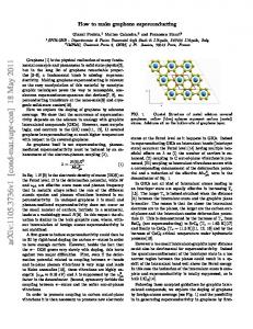
Figure 1: Verification time reduction methods provide better coverage of the design space than singlethreaded methods, but this comes at the price of verification performance, as multi-threaded methods require much more computational resources than do the single-threaded methods.
3.
BMC-BASED SEMIFORMAL VERIFICATION
In this section we describe our new SFV method. Our method is purely BMC-based, i.e. no simulation is involved, and thus no synchronization between dynamic and formal verification models is required.
3.1
Basic Algorithm
BMC is a powerful (and the most commonly used) FV technique that verifies the behavior of the DUT for input sequences of bounded length. It starts from the initial state of the DUT and searches for a run of one clock cycle that violates an assertion. If no assertion violation is found, the number of run cycles is iteratively increased. The number of different scenarios grows very quickly with the length of the run. The proposed BMC-based semiformal algorithm executes multiple shallow BMC runs, trading the exhaustiveness of a search for speed. The user provides an ordered set of waypoints which direct the search engine towards the desired deep design state. The algorithm searches for a path from one waypoint to the next, starting from the initial state; the BMC engine is restarted at each waypoint in order to avoid exponential blowup. This idea is illustrated in Fig. 1. The time needed to reach a deep design state is reduced from exponential to approximately linear in the number of clock cycles, which makes it possible in practice to get to states that would never have been reached with traditional BMC. As described in Section 2.2, some SFV methods automate the waypoint search and use various heuristics to guide the tool. In our approach, however, we let users provide high-level direction for the semiformal search towards the desired area by encoding the waypoints with SVA cover points. Our experience shows that, being familiar with design behavior, most users define these highlevel directions quite naturally. For example, consider a queue that requires 200 clock cycles to be filled. To validate the queue control logic in a stress "full queue" state, possible waypoints could be "1/4 full queue", "1/2 full queue", and "3/4 full queue", each waypoint being easily reached by the tool. We did implement an automation of the traversal, (see Section 3.4 for details), but our experience shows that most users prefer provide high level direction for the tool manually. The stages of the SFV flow are outlined in Fig. 2. First, the user defines a series of high-level waypoints modeled with SVA cover
User defines tool a series of high-level waypoints
bit q1, q2, q3, q4; initial {q1, q2, q3, q4} = ’0; // posedge clk is the assumption clock always @(posedge clk) begin q1


![[PDF] Download Leading Organization Design: How to Make ...](https://m.moam.info/img/260x300/pdf-download-leading-organization-design-how-to-ma_6477859e097c4744708bcdec.jpg)