AN EXPERIMENTAL INVESTIGATION OF SPATIAL REPEATABILITY Tom O’Connor1, Eugene J. O’Brien2 and Bernard Jacob3 1. Civil, Structural & Environmental Engineering, Trinity College, Dublin 2, Ireland; Tel: +353-1-2952321; Fax: +353-1-2954541; Email:
[email protected] 2. Civil Engineering, University College Dublin, Earlsfort Terrace, Dublin 2, Ireland; Tel: +353-87-2309931; Fax: +353-1-6083441; Email:
[email protected] 3. Laboratoire Central des Ponts et Chaussées, 58 Bd. Lefèbvre, F75732 Paris, Cedex 15, France; Tel: +33-1-40435312; Fax: +33-1-40435498; Email:
[email protected]
Abstract The results of an experimental road research project are presented which demonstrate the existence of spatial repeatability and show patterns of axle impact forces along a pavement. As part of the project, a section of highway near Paris, France, was instrumented with 18 Weigh-in-Motion sensors. Data was collected for a large number of vehicles over fourteen days between June 1994 and May 1995. For all the vehicles the impact factors were calculated and typical graphs are presented which show the variation of impact factor with distance along the sensor array. Mean impact factors and coefficients of variation are also presented and differences between steel and air suspensions are highlighted. The influence of vehicle speed on maximum impact factor is also considered. Keywords: weigh-in-motion, spatial repeatability, gross vehicle weight, axle weight, OECD/DIVINE, pavement, impact, suspension.
1. Introduction Spatial repeatability is the clustering of high dynamic axle loads at particular points along a road pavement. The existence of spatial repeatability is contrary to the traditional view that dynamic variations in axle load are randomly distributed along a road pavement and that, as a consequence, susceptibility to pavement damage is spread uniformly along the length of a road. If spatial repeatability occurs, then increased susceptibility to pavement damage would be expected to be concentrated at localised points.
Mitchell (1987) monitored instantaneous wheel forces using an instrumented vehicle performing repeated runs over a test track. He showed that for repeated runs of a given vehicle of a given speed and weight, similar patterns of dynamic force will be applied to a stretch of road. The amplitude of the loads were found to
1
vary by only 10 - 20% between runs. Gyenes and Mitchell (1992) further showed that this type of spatial repeatability for a given vehicle was consistently exhibited over a 16 month period. Huhtala et al. (1992) reached a similar conclusion to Mitchell (1987) using computer simulations. They also showed that if the speed varies on a smooth road, then spatial repeatability is lost. However, they reported that it took a very small unevenness of the road profile to put the pattern of dynamic forces back in place. Cole and Cebon (1992) and Cole et al (1996) investigated spatial repeatability using a non-linear two-dimensional vehicle simulation model. The model was validated by comparing the tyre force spectral densities with that of an actual vehicle. It was then used to generate a fleet of 37 geometrically similar leafsprung articulated vehicles with varying tyre and spring stiffnesses and varying vehicle and axle mass. It was concluded that approximately two thirds of four-axle leaf-sprung articulated vehicles may contribute to a repeating pattern of pavement loading. Vehicle speed was shown to be important in governing the spatial distribution of aggregate tyre forces. The dynamic forces of actual vehicles were measured using a load measuring mat by Cole and Cebon (1989). These mats contain capacitive sensors encapsulated in polyurethane 'tiles'. The sensors were tested at the Transport Research Laboratory (TRL) in the United Kingdom using 14 different vehicles. The spatial repeatability for different vehicles was found to be highly dependent on speed and on the combination of tractor/trailer suspensions. The mats were also tested at a highway site where it was found that half of the vehicles in normal traffic contributed to spatial repeatability. Since 1991 the TRL have been using an array of 18 weigh-in-motion sensors on the A34 motorway near Abington, England, to investigate spatial repeatability (Barbour 1993, Barbour & Newton 1995). Data was collected there over a short period for a total of 1936 vehicles travelling over a rough stretch of pavement. While the accuracy classification of the sensors was not reported, axle loading patterns were found to be highly repeatable and the degree of repeatability was found to be only slightly affected by speed and weight. A comparison of the loads imposed on road pavements by air and steel leafsprung semi-trailer suspensions was carried out by Mitchell (1987) using a road simulator. In simulations of rough roads, the air suspensions resulted in dynamic forces that were 7% less than those generated using steel suspensions. The air suspensions did produce higher dynamic forces when the wheel hop mode was excited. A comparison of air and steel suspensions fitted to commercial vehicles was carried out by Gyenes et al. (1992) and Gyenes and Simmons (1994). They showed that air suspensions result in lower dynamic forces than other types and
2
concluded that, if high dynamic forces were spatially repeatable, the use of air suspensions could reduce the cost of road maintenance by up to 40%. This paper reports the results of an investigation of spatial repeatability on a smooth pavement. The French road and bridge research institute, Laboratoire Central des Ponts et Chaussées (LCPC), installed 18 WIM sensors in a section of pavement on the RN10 highway near Paris. In addition to spatial repeatability, the experiment was intended to identify differences in patterns of dynamic force between steel and air suspensions. This French experimental programme was part of Element 5 of the Dynamic Interaction of Vehicles and INfrastructure Experiment (DIVINE) sponsored by the Organisation for Economic Co-operation and Development (Huhtala and Jacob 1995).
2. Site Details The site of the French experiment is the RN10 highway at La Verriere (Yvelines), near Trappes, 35 km SW of Paris. The traffic flow is approximately 30 000 vehicles per day, of which about 25% are Heavy Goods Vehicles (HGV’s). The road consists of 2 lanes in each direction. The pavement is of quite good quality and is relatively smooth with Longitudinal Profile Analyser (APL) ratings of 7, 7, and 6 in the small, medium, and long wavelength ranges respectively. The IRI rating is 1.71 m/km. In all, 18 WIM bars, each 3.20m long, were installed in the pavement in May 1994. They were piezoelectric reinforced with fiberglass, manufactured by Transfibre (Violette and Fillastre 1995). Underground cables connected the WIM bars to a nearby shelter. The WIM bars were installed at non-uniform distances: 7 bars at 0.375 m apart, then 4 bars at 1.125 m apart and finally 7 bars at 2.25 m apart. The total grid length was therefore 22.5 metres. Installed in the shelter were three SAFT 2000 weigh-in-motion stations designed by LEEM (France), each controlled by a micro-computer with an 80486 microprocessor. Each of these stations can manage eight WIM bars and is connected to an induction loop which detects the presence of a vehicle. The station records the instantaneous passage of axles, the speeds, lengths and types of vehicles, the force of impact of each axle and the cumulative total weight of the axles giving the gross weight. Initial pre-calibration of the WIM sensors using pre-weighed vehicles was carried out in May 1994 to centre the response of each bar on the static weight. The system was fully calibrated for axle impact forces in June 1994 using an instrumented HGV supplied by the Canadian National Research Council. This vehicle is capable of measuring axle forces at a sampling frequency of 500 Hz with a stated precision of 3%. It consists of a 3-axle tractor and a 3-axle semitrailer one axle of which can be lifted. Air suspensions were used at this site for 91 passes in 5 load configurations and at 3 speeds. For each pass, the calibration 3
coefficient was calculated as the ratio of the gross impact force given by the truck to that given by the sensor where gross impact force is the sum of the axle forces. The calibration coefficient used was the mean for all passes of the instrumented vehicle. A recalibration was performed after December 1994 to correct some sensor drift. The correction was implemented by multiplying the calibration factors by the ratio of the static calibration factors calculated in May 1994 to corresponding static values found from repeated runs of the laboratory vehicle. Further details on the calibration of the sensors is given by Huhtala and Jacob (1995).
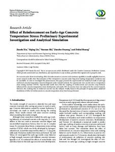
3. Data Collection Data was collected for vehicles that were pre-weighed and for vehicles that were in the total traffic flow. For the collection of pre-weighed vehicle data, trucks were selected from the general traffic flow and directed to the static weigh-bridge, where the static weights were recorded axle-by-axle. The types of suspension were also noted. The registration and description of the vehicle were then radioed ahead to the WIM station so that the particular truck could be recognised as it passed over the WIM sensors. Pre-weighed data was collected for 76 vehicles over six separate days on June 20th, July 6th and December 13th and 14th, 1994 and on April 4th and May 15th, 1995. On December 14th, 1994 a laboratory vehicle also made 11 repeated runs over the WIM sensors at various speeds. For the data collected on December 13th and 14th, only two SAFT 2000 stations were available, and thus two of the sensors, Nos. 17 and 18, were not connected. Also it was found that, beginning on December 13th, 1994, Sensor No. 2 suffered a loss of sensitivity which resulted in lower force values being recorded. In order to carry out the analysis on a homogeneous WIM array, it was therefore decided that Sensor Nos. 17 and 18 and Sensor No. 2, from December 13th 1994 onwards, should be left out of the analysis. The breakdown of pre-weighed trucks by type is given in Table 1. The types, illustrated in Figure 1, are in accordance with the French (and some European) classification systems. Data for 7 different vehicle types was collected, mostly of Types 1, 4 and 5. Data for trucks with semitrailers 2S2 and 2S3 (Types 4 and 5) comprised 74% of the total data. Data for single rigid trucks (Types 1 and 2) comprised 21% of the total. This sample composition is in quite good agreement with the general traffic composition on the RN10 highway, as will be seen in the next paragraph. The average speed of vehicles surveyed during these days, including a laboratory vehicle, was 73.4 km/hour. The laboratory vehicle was run at speeds lower than typical highway levels to investigate the influence of speed on the pattern of spatial repeatability. Over 80% of vehicles travelled in the speed range 70-90 km/hour.
4
Figure 1. Vehicle type silhouettes Collection of total traffic flow data took place over 9 days from May 3rd to 10th, 1995. Over these days, data was automatically recorded by the WIM stations for a total of 2976 vehicles. Total traffic flow data was collected for 12 different vehicle types; the breakdown by type is given in Table 2. Again trucks with semitrailers, 2S2 and 2S3 (Types 4 and 5) were the most frequent type of vehicle making up 65% of the total data. Single rigid trucks (Types 1 and 2) constituted 20% of the total. These figures are close to those from the sample of pre-weighed trucks. The average speed recorded for total traffic flow was 79.1 km/hr with 90% of the vehicles travelling within the speed range 70-90 km/hr. It was concluded that the sample of pre-weighed trucks was representative of the complete HGV traffic. Table 1. Pre-weighed vehicle type composition. The asterix indicates the 11 repeated runs of the laboratory vehicle
Type 1 Type 2 Type 3 Type 4 Type 5 Type 6 Type 7 Type 8 Total
June 20th 0 0 0 1 7 0 0 0 8
July 6th 2 0 0 2 7 1 1 0 13
Dec. 13th 1 0 0 4 8 0 0 0 13
Dec. 14th 11* 1 0 4 4 1 0 0 21
April 4th 0 0 0 1 12 0 0 0 13
May 5th 1 0 0 1 5 0 0 1 8
Total 15 1 0 13 43 2 1 1 76
5
Table 2. Vehicle type composition (total-traffic flow)
Type 1 Type 2 Type 3 Type 4 Type 5 Type 6 Type 7 Type 8 Type 9 Type 0 Type B Type C Total
April 3rd 10 1 3 34 68 1 7 7 1 0 0 0 132
April 4th 113 33 12 210 243 5 29 16 12 0 3 0 676
April 5th 56 34 9 204 305 8 39 22 9 1 3 0 690
April 6th 118 35 16 206 172 3 31 6 8 0 5 0 600
April 7th 92 39 10 188 192 5 27 11 12 0 2 2 580
April 8th 13 1 2 22 46 1 5 0 5 0 0 0 95
April 10th 39 21 6 37 81 3 11 1 2 1 1 0 203
Total 441 164 58 901 1107 26 149 63 49 2 14 2 2976
4. Variation of Impact Factor by Vehicle and by Axle For each axle i of a pre-weighed vehicle j, the static weight WijST was known. At each WIM sensor k, the WIM weight, WijkDY was measured. Hence, the impact factor (IF), defined as the ratio of the WIM weight to the static weight, was calculated at each sensor. Summary statistics for pre-weighed vehicles of Type 1, 4 and 5 are presented in Table 3. Table 3. Summary statistics for pre-weighed trucks
Mean IF COV (%) Within 15% Within 10% Within 5% Mean Speed (km/hour) Speed Range (km/hour)
Type 1 Gross Axle 1.00 0.98 7.21 9.86 ----93 100 54 87 ----58.2
Type 4 Gross Axle 1.03 1.03 6.21 8.44 ----94 100 85 62 ----76.7
Type 5 Gross Axle 1.02 1.02 5.18 7.85 ----85 91 73 63 ----77.4
37.4
18.1
23.4
6
The mean impact factor for axles given in the table is the mean for all axles, sensors and vehicles, i.e.:
mean axle IF
1 ni n j n k
=
WijkDY ∑ ∑ ∑ ST i =1 j =1 k =1 Wij ni
nj
nk
where ni, nj and nk are the numbers of axles per vehicle, vehicles and sensors respectively. It can be seen in the table that the mean IF is not exactly equal (but close) to unity as might have been expected and that it depends on the vehicle type. An IF for gross vehicle weight is calculated as the ratio of the sum (for all axles of the vehicle) of the axle WIM weights to the statically weighed gross vehicle weight, i.e.: ni
∑W
DY ijk
gross IF
=
i =1 ni
∑W
ST ij
i =1
The mean IF’s for gross weight are also given in Table 3, where:
mean gross IF
1 n j nk
=
nj
nk
∑∑ j =1 k =1
ni DY ∑ Wijk i =1 ni ST ∑ Wij i =1
It can be seen that these are also not always equal (but again close) to unity. Coefficients of variation (COV) of the axle and gross vehicle IF’s are given as an indication of the variability. These are in the range of 6 to 10% with, as would be expected, lower values being recorded for gross vehicle weights than for individual axle weights. The percentages of measured WIM weights that were found to be within 15, 10 and 5% of the static value are also given in Table 3. Significant variations in results can be seen between truck types, reflecting the different dynamic characteristics of the vehicles. The final rows of Table 3 give the mean truck speed for the three truck types and the range in speed recorded for the pre-weighed trucks. The breakdown of mean IF’s and their coefficients of variation, axle by axle, is given in Table 4. In this context, the mean IF for axle i is defined as: WijkDY ∑∑ n j n k j =1 k =1 WijST
( mean IF ) i = 1
nj
nk
7
Table 4. Mean impact factors and coefficients of variation (COV) by truck type and axle number
Axle 1 Axle 2 Axle 3 Axle 4 Axle 5 Tandem/Tridem
Type 1 Mean COV IF (%) 0.9 8.83 1.05 9.86 ---------
Type 4 Mean COV IF (%) 0.95 6.79 1.06 7.52 1.06 9.91 1.03 9.54 --1.04 8.16
Type 5 Mean COV IF (%) 0.96 5.95 1.04 7.21 1.04 8.24 1.03 8.71 1.05 9.12 1.04 7.85
This data is illustrated in Figure 2 which gives the mean and the 95% confidence interval for IF for each axle. On average, Type 1 vehicles have lower mean IF’s for gross vehicle and axle weights than either Type 4 or Type 5 vehicles. Type 4 and Type 5 vehicles have similar mean IF’s. Figure 2 shows that Axle 1 of all types has significantly lower IF’s than the other axles. The low value of IF for Axle 1 has been noted by other authors (Peters et al. 1995) and may be a result of the transfer of load due to wind effects.
1.15 1.1
Axle Mean IF
1.05 1 Type 5 Type 4 Type 1
0.95 0.9 0.85 0.8 Axle 1
Axle 2
Axle 3
Axle 4
Axle 5
Figure 2. Mean impact factor and 95% confidence interval for each axle The force of wind on the front of vehicles tends to cause uplift. However, since the total weight of the vehicle remains constant, the load is transferred to the rear axles of the vehicle. There do not appear to be any significant differences on an 8
axle-by-axle basis for Type 4 and 5 vehicles. In addition the values of mean IF for tandem and tridem bogies are the same. The coefficients of variation for all axles are in the range of 6 to 10%. It can be seen that Axle 1 recorded the lowest coefficients of variation (COV). For both Type 4 and 5 vehicles, the trailer axles gave the highest COV values. In the case of Type 4 vehicles, Axle 3 had the highest COV while, for Type 5 vehicles, Axle 5 had the highest COV. The percentages of measured WIM axle weights that were found to be within 10 and 15% of the static values are given in Table 5. Type 4 vehicles weighed more accurately than the other vehicle types, i.e., generally a greater number of Type 4 vehicles were within these accuracy limits. Tandem bogies weighed more accurately than Tridem bogies to within a 13 percentile limit. A large percentage of individual axle load results are within the 15 percentile limit. Table 5. The percentages of measured WIM axle weights found to be within 10% and 15% of their static values (values for Tandem/Tridem are those within 7% and 13% respectively)
Axle 1 Axle 2 Axle 3 Axle 4 Axle 5 Tandem/Tridem
Within 10% Type 1 Type 4 Type 5 27 92 84 80 85 84 -62 67 -100 67 --63 -54 58
Within 15% Type 1 Type 4 Type 5 93 100 98 93 100 93 -77 79 -100 79 --74 -100 74
5. Variation of maximum IF with suspension type and speed The investigation of the correlation between IF and suspension type could only be carried out for Type 5 vehicles. This was because there was insufficient data on air suspensions to make an analysis for other truck types worthwhile. Table 6 gives the numbers of records of each suspension type for each axle. Figure 3 shows the mean for all axles of a type, of the maximum IF for all sensors, i.e.:
( mean maximum IF ) i =
1 nj
nj
∑ j =1
WijkDY max k W ST ij
9
Table 6. Frequency of occurrence of each suspension type
Steel Suspension Air Suspension
Axle 1 Axle 2 33 29 10 14
Axle 3 16 27
Axle 4 16 27
Axle 5 16 27
The 95% confidence intervals are also indicated in the figure. It can be seen that, for Axles 1 and 2, there is no significant difference in the maximum IF’s between air and steel suspensions. For the tridem axles however (Axles 3, 4 and 5), the differences in maximum IF for steel and air suspensions do appear to be significant. For these axles, steel suspensions have values of maximum IF which are on average 11% higher than those for air suspensions which corresponds to a dynamic increment (IF-1) which is twice as high.
1.4
1.3
Maximum IF
1.2 Steel Air
1.1
1
0.9
0.8 Axle 1
Axle 2
Axle 3
Axle 4
Axle 5
Figure 3. Maximum impact factors for air and steel suspensions
In order to assess the relationship between the IF’s and the speed of the vehicle, values of the maximum IF were plotted against speed. A typical plot is given in Figure 4 for the tridem axles of Type 5 vehicles. Table 7 gives the linear correlation coefficients which were determined for this data. The results, with the exception of Type 1 trucks, show very low values for the correlation coefficients which is a result of the great deal of scatter in the data. It is likely that the low values for Types 4 and 5 are influenced by the relatively small speed ranges of the data collected for these vehicle types. The majority of results were positive indicating that the values of maximum IF generally increased with increasing speed.
10
Table 7. Coefficients of correlation between maximum IF and speed
Type 1 Type 4 Type 5
Gross Weight 0.44 0.06 0.09
Axle 1
Axle 2
Axle 3
Axle 4
Axle 5
0.65 -0.32 -.01
0.40 -0.10 0.07
-----0.12 0.11
----0.50 0.10
--------0.14
Tandem / Tridem ----0.31 0.12
1.4
1.3
Maximum IF
1.2
1.1
1
0.9
0.8 60.0
65.0
70.0
75.0
80.0
85.0
90.0
95.0
Speed (km/hr)
Figure 4. Maximum impact factors for different speeds for tridem axles of Type 5 vehicles
6. Spatial Repeatability
To examine more specifically spatial repeatability, the multiple-sensor WIM array was used to illustrate the relationship between IF and distance along the pavement. Firstly, repeated runs of a laboratory vehicle known as the ‘deflectometer’, are considered. This vehicle was driven repeatedly a number of times within each of two speed ranges in order to investigate spatial repeatability under ‘repeatability conditions’, i.e., the same vehicle travelling several times at the same speed. The deflectometer was a Type 1 vehicle and had a static mass of 19 tonnes. It was run five times at approximately 45 km/hour and six times at approximately 58 km/hour. The IF’s for Axle 2 of the vehicle for the two speeds are given in Figures 5 and 6. The graphs show strong evidence of spatial repeatability, particularly for the lower speeds. However there are differences in
11
amplitudes of between 10 and 15% at some sensors. It is also clear from the graphs that that the patterns of IF are different for the two speed ranges, the lower speed producing a more cyclical pattern.
1.25 1.20 1.15 43.3km/hr 44.6km/hr 44.8km/hr 46.1km/hr 47.6km/hr
1.10 IF
1.05 1.00 0.95 0.90 0.85 0.80 0
2
4
6
8
10
12
14
16
18
Distance along Pavement (m)
Figure 5. Impact Factors for Axle 2 of Deflectometer at speeds 43.3-47.6 km/hour
1.25 1.20 1.15 1.10 57.1km/hr 58.7km/hr 58.8km/hr 59.0km/hr 59.0km/hr 59.1km/hr
IF
1.05 1.00 0.95 0.90 0.85 0.80 0
2
4
6
8
10
12
14
16
18
Distance along Pavement (m)
Figure 6. Impact Factors for Axle 2 of Deflectometer at speeds 57.1-59.1 km/hour
12
Analysis of the pre-weighed vehicle data is considered next. Typical graphs of IF versus distance along the pavement are presented in Figure 7 which gives the Axle 1 IF’s for eight different trucks of Type 5.
1.20 1.15 1.10 1.05
Truck 1 (s) Truck 2 (s) Truck 3 (a) Truck 4 (s) Truck 5 (s) Truck 6 (s) Truck 7 (s) Truck 8 (s)
IF
1.00 0.95 0.90 0.85 0.80 0.75 0.70 0
2
4
6
8
10
12
14
16
18
Distance along Pavement (m)
Figure 7. Impact factors for Axle 1 of Type 5 trucks on December 13th, 1994 (s = steel suspension, a = air suspension)
There is clearly a very high degree of variation in the patterns of IF, almost to the point of apparent randomness. It is clear from this graph that even for axles of the same vehicle and suspension type, the patterns of IF produced can be quite different. Figure 8 gives the mean gross weight IF for Type 5 vehicles for each of the six days of weighing, i.e.:
(mean gross IF )
k
=
1 nday
nday
∑ j =1
ni DY ∑ Wijk i =1 ni ST ∑ Wij i =1
where nday is the number of vehicles per day. While the patterns of IF show some general trends, especially from a distance of 10 m onwards, there are relatively large differences in the values of the mean IF’s over the six days.
13
1.20 1.15 1.10
June 20, '94
IF
July 6, '94
1.05
Dec. 13, '94 Dec. 14, '94
1.00
April 4, '95 May 15, '95
0.95 0.90 0
2
4
6
8
10
12
14
16
18
Distance along Pavement (m)
Figure 8. Mean Impact Factors for gross vehicle weights of Type 5 vehicles.
The patterns of mean IF for Axle 1 are illustrated in Figure 9 where:
( mean IF ) 1k
=
1 nday
nday
∑ j =1
W1DY jk ST W1 j
There is more variation in these patterns than in those for the gross vehicle weight. The conditions under which these Type 5 trucks were weighed could be considered as ’extended repeatability conditions’, i.e., several vehicles of the same type with a small speed range. It can be concluded that, for such conditions, the impact force variations are influenced by the dynamic characteristics and the dimensions of the vehicles. There are some differences of axle spacing and suspension parameters (damping, dry friction, inertia, etc.) within the population of the vehicles of one type. These differences induce scattering in the pattern of IF. The lower the repeatability conditions, the higher the scattering of the IF patterns. For the total traffic flow data, the static weight was estimated as the average of the WIM weights over the fifteen sensors. Typical results are presented in Figures 10 and 11. These graphs give the mean IF’s for gross vehicle weight for Type 3 and 5 vehicles respectively for each of the seven days, i.e.:
14
(mean gross IF )
k
=
nday
1
nday
∑ j =1
ni WijkDY ∑ i =1 ni nk W DY ∑ ∑ ijk nk i =1 k =1
1.10 1.05 1.00
June 20, '94
IF
July 7, '94
0.95
Dec. 13, '94 Dec. 14, '94
0.90
April 4, '95 May 15, '95
0.85 0.80 0
2
4
6
8
10
12
14
16
18
Distance along Pavement (m)
Figure 9. Mean Impact Factors for Axle 1 of Type 5 vehicles.
1.20 1.15 1.10 April 3, '95
1.05 IF
April 4, '95
1.00
April 5, '95 April 6, '95
0.95
April 7, '95
0.90
April 8, '95 April 10, '95
0.85 0.80 0
2
4
6
8
10
12
14
16
18
Distance along Pavement (m)
Figure 10. Mean Impact Factors for gross vehicle weights of Type 3 vehicles from total traffic flow 15
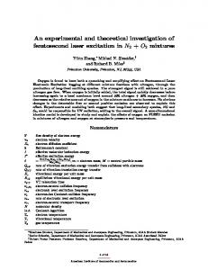
In the case of the Type 5 vehicles (Figure 11) for which data was collected from 1107 trucks in total, there is clear evidence of spatial repeatability. The range of loading is within a relatively narrow band from 5% below the static weight to 10% above it. Figure 10 is based on 58 Type 3 vehicles and the results are more scattered. It is clear that the degree of spatial repeatability shown depends on the number of vehicles for which data is collected and that large quantities of data are required before a pattern of strong spatial repeatability becomes evident.
1.20 1.15 1.10
IF
1.05
April 3, '95 April 4, '95
1.00
April 5, '95
0.95
April 6, '95 April 7, '95
0.90
April 8, '95 April 10, '95
0.85 0.80 0
2
4
6
8
10
12
14
16
18
Distance along Pavement (m)
Figure 11. Mean Impact Factors for gross vehicle weights of Type 5 vehicles from total traffic flow
This phenomenon may be called ‘Statistical Spatial Repeatability’, a convergence of the mean IF pattern when the number of individual records increases to a ‘critical pattern number’. Statistical Spatial Repeatability is characteristic of a given site and is largely governed by the pavement. For a small sample of vehicles, the ‘vehicle effect’ due to the dimensions and dynamic parameters, strongly influences the IF and the effect of the pavement is suppressed. When the sample size increases however, the different influences of many individual vehicles compensate and the pavement effect becomes dominant. Figure 12 provides a comparison of IF’s for gross vehicle weight from the full traffic flow for vehicles of nine different types. The patterns of IF produced are very similar for the different vehicle types and those for trucks of Type 4 and 5 are almost identical. It appears that vehicle type had little significance on the patterns
16
of IF produced and that, if equally large quantities of data were collected for all vehicle types, they could be expected to show similar IF patterns. It can thus be concluded that, under reproducibility conditions (different vehicle types), Statistical Spatial Repeatability remains.
1.2 1.15 1.1 Type1
IF
1.05
Type2
1
Type3
0.95
Type5
Type4 Type6 Type7
0.9
Type8 Type9
0.85 0.8 0
2
4
6
8
10
12
14
16
18
Distance along Pavement (m)
Figure 12. Impact Factors for gross vehicle weights for vehicles of Type 1-9
This conclusion is of very great importance for pavement design because of the implications for fatigue damage. Even with quite good pavement evenness as is the case for the RN10 highway, it is evident that some sections of pavement are repeatedly subjected to impact forces which are about 8% higher than the mean. Pavement damage is often taken to be a function of impact force raised to the fourth power and is generally taken to be a function of impact force raised to a power of between 4 and 8. Damage to the critical section is therefore increased by between 36% and 85% and the expected lifetime, which is controlled by the weakest section, is correspondingly reduced. For impact forces 10% higher than the mean, the corresponding increases in pavement damage are in the range of 46% to 114%.
7. Conclusions
As part of an experimental investigation into spatial repeatability, WIM data was collected for 76 vehicles for which the static axle weights were measured and for 2976 other vehicles from the full traffic flow. The pre-weighed vehicle data was
17
analysed in order to examine the variation of IF with axle, suspension type and speed. It has been shown that, for trucks of Type 1, 4 and 5, Axle 1 recorded the lowest mean IF and coefficient of variation. With the exception of Axle 1, the differences in mean IF on an axle-by-axle basis were not statistically significant. The reason for the low values for Axle 1 may be the transfer of load to the rear of the vehicle due to wind effects. There were no significant differences between the maximum IF’s for steel and air suspensions for Axles 1 and 2. However there were significant differences between them for the tridem axles. For these axles steel suspensions recorded values of maximum IF which were on average 11% greater than those for air suspensions. It was found that increasing speed gave rise to slightly higher values for the maximum IF’s although results were quite scattered and this analysis was based on a narrow range of speeds. For Type 1 vehicles, which had a larger range of speeds, there was a stronger positive correlation between speed and maximum IF. Spatial Repeatability was only shown clearly for vehicle types for which a large quantity of data was available. For pre-weighed vehicles taken from the general traffic flow there was a large scatter of results, and spatial repeatability was not clearly evident. For repeated runs of the Deflectometer laboratory vehicle, there was strong evidence of spatial repeatability even for a small number of runs. At different speeds the patterns of IF were observed to have changed. For the total traffic flow there was clear evidence of spatial repeatability. Vehicles of different types also produced very similar patterns over the sensors.
References
1 Barbour I.A., Dynamic wheel loading on the A34 at Abingdon, Project Report 46, Transport Research Laboratory, United Kingdom, 1993. 2 Barbour I.A. and Newton W.N., “Multiple-sensor weigh-in-motion”, in Post Proceedings of First European Conference on Weigh-in-Motion of Road Vehicles, eds. B. Jacob et al., ETH, Zürich,1995, pp133-142. 3 Cole, D.J. and Cebon, D., "A capacitive strip sensor for measuring dynamic tyre forces", in Post Proceedings of Second International Conference on Road Traffic Monitoring, Institute of Electrical Engineers, London, 1989. 4 Cole, D.J. and Cebon, D., "Spatial repeatability of dynamic tyre forces generated by heavy vehicles", Journal of Automobile Engineering, Proceedings of the Institute of Mechanical Engineers, Vol. 206, 1992, pp 1727. 5 Cole, D.J., Collop, A.C., Potter, T.E.C. and Cebon, D., "Spatial repeatability of measured dynamic tyre forces", Journal of Automobile Engineering,
18
6
7
8
9
10
11
12
13
Proceedings of the Institute of Mechanical Engineers, Vol. 210, No. D3, 1996, pp 185-197. Gyenes L. and Mitchell C.G.B.. “The spatial repeatability of dynamic pavement loads caused by heavy goods vehicles”, in Post Proceedings of Third International Symposium on Heavy Vehicle Weights and Dimensions, eds. D. Cebon et al., Cambridge, United Kingdom, 1992, pp 95-101. Gyenes L. and Simmons I.C.P., The dynamic performance of suspension systems fitted to commercial vehicles, Project Report 74, Transport Research Laboratory, United Kingdom, 1994. Gyenes L., Mitchell C.G.B. and Phillips, S.D., “Dynamic pavement loads and tests of road-friendliness for heavy vehicle suspensions”, in Post Proceedings of Third International Symposium on Heavy Vehicle Weights and Dimensions, eds. D. Cebon et al., Cambridge, United Kingdom, 1992, pp 243251. Huhtala M.S., Pihlajamak J.T. and Halonen P.A., “WIM and dynamic loading on pavements”, in Post Proceedings of Third International Symposium on Heavy Vehicle Weights and Dimensions, eds. D. Cebon et al., Cambridge, United Kingdom, 1992, pp 272-277. Huhtala, M.S. and Jacob B., “OECD DIVINE Project - Spatial repeatability of axle impact forces”, in Post Proceedings of First European Conference on Weigh-in-Motion of Road Vehicles, eds. B. Jacob et al., ETH, Zürich,1995, pp121-132. Mitchell, C.G.B., The effect of the design of goods vehicle suspension on loads and bridges, Project Report 115, Transport Research Laboratory, United Kingdom, 1987. Tierney, O.F., O’Brien, E.J. and Peters, R.J., “The Accuracy of Australian and European Culvert Weigh-in-Motion Systems”, in National Traffic Data Acquisition Conference ‘96 (NATDAQ ‘96), Vol. II, ed. G. Knoebel, Alliance for Transportation Research, Albuquerque, New Mexico, 1996, 647-656. Violette E. and Fillastre D., “A new WIM bar reinforced with glassfibre”, in Pre-Proceedings of First European Conference on Weigh-in-Motion of Road Vehicles, eds. B. Jacob et al., ETH, Zürich,1995, pp 355-360.
19