An Exploratory Case Study of Testing in an Automotive Electrical System Release Process Daniel Sundmark
Kai Petersen
Stig Larsson
MRTC, M¨alardalen University V¨aster˚as, Sweden
[email protected]
Blekinge Institute of Technology Karlskrona, Sweden
[email protected]
MRTC, M¨alardalen University V¨aster˚as, Sweden
[email protected]
Abstract—The release process is a crucial element in the development of software-intensive systems, as it bridges the gap between the development of a system and its operational use. A short release process enables a fast time to market, but also puts high demands on the efficiency of integration and testing, which typically constitue principal release process steps. This paper reports findings from an exploratory industrial case study focusing on system testing in an automotive electrical system release process. We provide a description of how system testing is performed and integrated in the release process in the automotive domain, and identify a set of challenges observed in the studied setting. The case being studied is Scania, a major Swedish automotive company.
I. I NTRODUCTION In system development, a release process dictates the steps that are to be undertaken within the development organization to make sure that a well-packaged high-quality system is delivered timely to the awaiting customer. As such, the release process bridges the gap between the development of a system and its operational use [20]. As the release process details the final steps before the system is delivered to the customer, there is a natural inclusion of verification and validation activities. In this study, we particularly focus on system testing in the release process. Beizer [4] describes system testing as follows: “System testing is aimed at revealing bugs that cannot be attributed to components as such, to the inconsistencies between components, or to the planned interactions of components and other objects. System testing concerns issues and behaviors that can only be exposed by testing the entire integrated system or a major part of it.” We admittedly make use of a broader definition of system testing than Beizer does, partially including what he would refer to as integration testing. In this paper, the term system testing is used to denote all testing where (1) the testing is performed by individual organizational entities with an explicit focus on electrical system testing, and (2) the testing is performed on a system or sub-system that is the result of the integration of several different sub-systems or modules. With regard to system testing in the context of the automotive domain, with a tight hardware-software connection, and their specifics in the testing process, little evidence on how the testing is performed in this context exists, and the challenges in system testing in the automotive domain have not been evaluated [6]. Accordingly, the objectives of the study are (1)
to describe how system testing is performed in an automotive domain company, and how it connects to a frequent release cycle of three months, and (2) to identify challenges related to system testing with frequent releases in the context of the automotive domain. The research method used was an exploratory case study [25]. The data collected is based on open interviews and the study of documentation. In total 16 open-ended and non-structured interviews have been performed. The paper is structured as follows: Section II discusses related work and Section III describes the research method used in the study. Section IV provides the study results, Section V discusses the theoretical and practical implications of these results, and Section VI concludes the paper. II. R ELATED W ORK A review of research in test, verification, and validation in the automotive and vehicular domains reveals that contributions in this area are dominated by methods developed for the purpose of low-level model-based testing and verification (see e.g., [5], [13], [18]). Studies focusing on integration- and system level testing of automotive systems are sparse, and this shortage is also highlighted by other researchers [6]. However, based on the studies that do exist in this area, it is possible to derive a set of main challenges that have been reported regarding system testing of automotive systems. Challenges with respect to high level testing that were mentioned in studies with an automotive focus are summarized in Table 1, and are discussed in detail below: C1 : First and foremost, there is reportedly a strong tradition in the automotive industry of building cars by integration of modular third-party components. This is a tradition that has also been adopted by automotive software engineering [3], [8], [16], [17]. While financially beneficial from a development cost per component-perspective (since standard automotive components can be developed once for several OEMs (i.e., vehicle manufacturers)), a consequence of this subcontracting culture is that the development process, including requirements engineering, implementation, integration and testing, needs to cross organizational borders. According to Grimm [8], having subcontractors part of the development process might significantly complicate system integration and testing, e.g., in
TABLE I C HALLENGES IN AUTOMOTIVE SOFTWARE SYSTEM TESTING AS DESCRIBED BY RELATED WORK . ID C1 C2 C3 C4 C5 C6
Challenges Reported in Related Work To a large extent, automotive software is subcontracted rather than developed in-house, making system verification more difficult [3], [8], [16], [17]. Early integration testing is hampered by hardware dependencies and lack of hardware availability [2], [12]. Mass-customization of vehicles calls for massive configuration and variant testing [17]. The safety-critical nature of some vehicular subsystems poses additional requirements on their verification [8], [17], including safety concerns of early system testing in a real setting [22]. A steadily increasing number of functions are distributed and require integration for testing [17]. Overlapping tests at different levels cause waste of testing time and resources [11].
the form of communication being hampered by organizational and geographic distribution. C2 : Insights into the exponentially increasing corrective costs relative to the time of defect detection in the development process in general software engineering has emphasized the importance of early testing, even at higher levels of integration. In the case of automotive software engineering, as in most embedded software development, system integration early in the development process is often hindered by lack of target hardware access [2], [12]. C3 : Another challenge, reported by Pretschner et al. [17] relates to variant handling. As a customer, you often want the opportunity to customize your vehicle. Different alternative selections of, e.g., gearbox, engine or driver interface will also lead to corresponing selections in the electrical system configuration. This means that each individual subsystem selection needs to function properly in every possible integrated system configuration (or that the organization keeps track of which combinations that are incompatible and impossible to select). Naturally, the list of available subsystem configurations also varies over time, and with the long lifetime of automotive systems, it is required that backward compatability spans over decades. Hence, when you are testing an automotive system, you are really testing a family of systems, most often subject to combinatorial explosion. C4 : Automotive systems are heterogeneous in nature, but nearly all such systems include subsystems with strict requirements on safety and reliability (e.g., braking and engine control) [8], [17]. Testing plays a major part in the safety assurance of these subsystems. This challenge is further complicated by the level of integration between the non-safety critical subsystems and the safety critical ones. It is of utmost importance that the non-safety critical systems are not allowed to hinder the safe operation of the safety critical ones. In addition, this safety criticality also restricts the possibility of early testing in a real setting, since such testing would potentially endanger the safety of both the driver and other individuals [22]. C5 : Related to the above, in the automotive domain, there is a trend towards more and more complex functionality, whose implementation is distributed over several previously isolated subsystems [17]. Examples include electronic stability control, which, in the most complex case, require interaction between the braking, engine control and transmission systems. Functions distributed over several subsystems requires performing
(sub)system integration before function testing, which in turn adds to the responsibility of integration testing. C6 Finally, Perez and Kaiser report on an observed overlap between different test levels in automotive systems development [11]. The authors state that “The strict separation of test levels results in similar or even identical test cases being separately specified, implemented, and executed at different test levels.”. III. R ESEARCH M ETHOD The research method used is an exploratory case study. In contrast to descriptive case studies, exploratory case studies do not require or assume a priori formulation of hypotheses or theories. The reason for choosing an exploratory case study method was that there is little evidence reported on how automotive companies approach testing in short release cycles. A. Research Questions The research questions can be directly linked to the two objectives formulated in the introduction. 1) How are integration and system testing performed in the context of software development in the automotive domain, with frequent releases to the market that are tightly coupled with the release of hardware (vehicles)? 2) What challenges does the automotive domain in the described context face, and how do they compare to already known challenges in the domain? B. Case, Context, and Unit of Analysis The case being studied is Scania CV1 , a Swedish truck and bus manufacturer. The context of the case study can be characterized based on the checklist provided in Petersen and Wohlin [15]: Scania is developing for a mass market, i.e. their development is market-driven with a large set of potential customers. The products being developed are real-time and safety critical systems, and are based on product-lines with a high degree of variability. The development is completely colocated at one single site. The unit of analysis is the Scania Electrical System. The Scania Electrical System: SESAMM (i.e., Scania Electrical System Architecture made for Modularization and Maintenance) is the common electrical system used by all vehicles produced by Scania. SESAMM is a system of distributed Electronic Control Units (ECUs) that operate over 1 http://www.scania.com
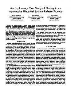
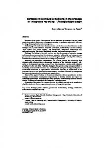
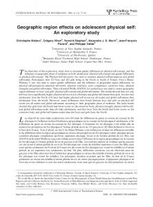
!"#$!" !"#$!#$" !"#$!#%" !"#$!#&" !"#$!#'" !"#$!#("
!"#$!"%&'($
!"#$!#%"%&'($ !"#$!#'"%&'($
!"#$!#$"%&'($
Fig. 1.
!"#$!#&"%&'($
!"#$!#("%&'($
A set of parallel SOPs over a period of time.
three different CAN buses, interconnected by a coordinator ECU system. The buses are categorized mainly based on the level of mission criticality of the ECU systems connected to each bus (or more specifically, the severity of consequences should the CAN bus communication fail). The Green bus connects ECU systems related to informatics, heaters, and climate control. The ECU systems on the Yellow bus relate to support functionality, e.g., visibility, diagnostics and instrumentation, and the Red bus mainly connects core functionality ECU systems, such as powertrain control and brake management. Note that we use the term ECU system to refer to an embedded ECU microcontroller, including hardware and software, within SESAMM. This is only partly compliant with the internal Scania terminology, which commonly uses the term system to refer to both individual ECUs, and to SESAMM as a whole. ECU System and User Function Owners: Each ECU system in SESAMM is “owned” by a person or role in the Scania organization (i.e., system owners). ECU system ownership indicates responsibility for that particular ECU system, and its development and evolution. Whenever changes to SESAMM affect a particular ECU system, the owner of that ECU system should be involved. At the level of abstraction above ECU systems in SESAMM lies the concept of user functions. While ECU systems mainly are isolated in their concern to a particular structural part of the vehicle (e.g., engine, driver interface, etc.), user functions focus on the fulfillment of (user initiated) tasks. As such, user functions are implemented through the collaborative functionality of the underlying ECU systems. In some cases, the implementation of a user function is isolated to a single ECU system, but often the implementation of user funtions requires the support of several ECU systems. As an example, the Retarder lever activated braking user function is triggered by the activation of retarder supported braking. The function should make sure that the brake lights are ignited, and that a notification of the retarder brake activation is shown on the
driver interface. Moreover, the user function needs to notify the master brake system of the retarder braking. In order to carry out all required activities, the retarder user function is supported by several underlying ECU systems. Similarly to ECU systems, user functions are owned by persons or roles in the Scania organization (i.e., user function owners). It is not uncommon for a ECU system owner to also hold ownership for a number of user functions that are mainly implemented on that particular ECU system. Customization: Customization is a primary matter for Scania. Basically, customers are allowed to customize their vehicles in great detail, including a high degree of freedom in the selection of several different variants of driver interface, gearbox, engine, exhaust system, etc. The definition of a particular vehicle customization is given in the form of a identifier string, which act as a vehicular “DNA string”. This string greatly affects the configuration of the SESAMM electrical system, since different vehicular components require different configurations of the corresponding controlling ECU systems, and different versions of the software embedded in those ECU systems. C. Data Collection and Analysis Triangulation, i.e., consulting multiple sources of evidence, is an important concept in case study research [25]. There have been three major sources of data for this study: Documentation: Company-internal documentation of the release process, including integration and system testing, as well as internal documentation of the electrical system. This documentation mainly consists of presentation material developed by subfield experts for the purpose of company-internal process communication and dissemination, but also includes internal technical reports, meeting notes, and the internal web pages. Open-Ended Interviews: 16 informal 1-2 hour interviews with the system test group-, and ECU system test group leaders, system architects, and other specialists within the
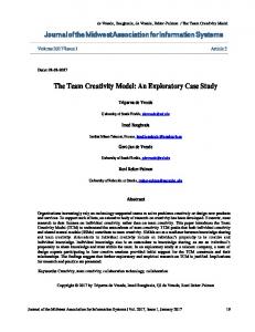
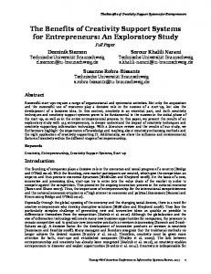
.,/#0#1"' +,,$"-' (2%32'14' *3156/$1"'
Fig. 2.
%#$%*-0) !1.$#)6)3!64)
%#$%*-0) !1.$#)5)3!54)
%#$%*-0) !1.$#)2)3!24)
.,/#0#1"' +,,$"-' *+!,#+#-%.%*/-)
!"#$%&'()
!"#$%&'()*' +,,$"-'
The life cycle of a SOP.
organization. The interviews were non-structured, and the interview questions were generally open-ended. However, all interviewees were informed of the purpose of the interview (i.e., a mapping of system testing in the release process), and were asked to describe the role of their respective organizational unit in the release process. Moreover, frequently asked questions include questions about the internal release frequency, planning and prioritization processes, and the testing practices in the interviewee’s organizational unit. Interview notes were recorded by hand. Member Checking: All interviewees received a copy of an early version this report, and were given the opportunity to comment on any misunderstandings or inconsistencies that ware included. Five interviewees provided feedback, out of which three stated nothing but satisfaction with the contents. Two interviewees provided a number of minor suggestions for improvement. These suggestions were later incorporated in the final version. The analysis was done in three steps. First, a description of the release process was created based on interviews and process documentation. Thereafter, challenges and desired improvements were extracted from the notes being taken. In the third step, the challenges were synthesized and their potential implications for research and practice analysed. D. Validity threats Four types of validity threats are generally distinguished, namely construct validity, internal validity, external validity, and reliability [24]. Construct Validity: Construct validity aims at obtaining the right measures for the concept being studied. One threat was to obtain appropriate people to answer the research questions. The threat was reduced by having support from the company in selecting people with good knowledge of the release and testing process. An open threat was that the presence of the researcher might influence the outcome of the study due to that the researcher is being perceived as external. Internal Validity: Internal validity is primarily a concern of descriptive case studies and experiments. As this study does not seek to confirm a theory or proposition, this type of validity is not threatened.
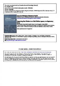
External Validity: External validity is concerned with the generalization of the results. This is always a challenge in industrial case studies. The threat is reduced by carefully describing the context and units of analysis, so that the degree of generalizability becomes explicit. We believe the results are generalizable to a high degree within the automotive domain, as similar challenges are observed. For example, in general the automotive industry deals with the issue of customizability and short releases. Reliability: Reliability concerns the ability to replicate the study. As the interviews were open-ended, they cannot be exactly replicated. However, the interview goals were clearly stated, and hence with these goals in mind the study should be replicable in other contexts. Another threat is that the interpretation of the researcher affects the outcome. To mitigate this risk two actions have been taken. Several sources of information were consulted, and member checking was conducted to confirm whether the information collected was interpreted correctly. IV. R ESULTS This section presents the results of the exploratory case study, and provides answers to research question 1 (Section IV-A) and research question 2 (Section IV-A2). A. The Release Process and System Testing 1) The Electrical System Release Process: At the topmost level of integration, a new increment of the SESAMM electrical system is released quarterly. However, internal releases of individual ECU systems may occur more frequently (or infrequently). Start of Production A central aspect of the release process of the electrical system at Scania is the concept of Start of Production (SOP). By definition, a SOP date is a point in time where a certain version of the electrical system goes into production, but the term SOP is also used to denote the package of new and existing functionality that is scheduled to be released at the sop date. Additionally, the term “SOP” may be used to refer to the process leading up to the release of this functionality (i.e., the particular instance of the release process). Basically, any planned change to the system is defined in the form of a change request, which in turn is
)*')"+$,-.%&("/%
+!-)$()-.%&("/%
!""#$%&'"#(%#)*'+(
!"#
%$,'(
%$8,9()3)%#.(%#)*'+(
!"&
%$'"&#%
!"(
%$F>@B8>(@A?8>5!,8(
7&4%()3)%#.(%#)*'+( 7&4%(2'%#+4&*-'(%#)*'+(
5D88?(:E:?(
56'"*-'(%#)*'+(
7?>!@A(
,-.$/#%#(0#12"/#(2'%#+4&*-'(%#)*'+( B8C@,D8(,