Research Projects Agency and Rome Laboratory, Air Force Mate- ..... geoloc-code ... The slot medical-specialty-required specifies the particular constraints.
An Exploratory Prototype for Reactive Management of Aeromedical Evacuation Plans Ora Lassila, Marcel Becker, Stephen F. Smith CMU-RI-TR-96-03
The Robotics Institute? Carnegie Mellon University Pittsburgh, PA 15213 February 1996
c 1996 Ora Lassila, Marcel Becker and Stephen F. Smith
?
The aeromedical evacuation application of the DITOPS Planning and Scheduling Framework described in this paper was supported by a research grant from Carnegie Group Inc. Development of the DITOPS framework itself was sponsored in part by the Advanced Research Projects Agency and Rome Laboratory, Air Force Material Command, USAF, under grant numbers F30602-90-C-0119 and F30602-95-1-0018 as well as F30602-91-C-0014 (under subcontract to BBN Systems and Technologies), and the CMU Robotics Institute. The views and conclusions contained herein are those of the authors and should not be interpreted as necessarily representing the official policies or endorsements, either expressed or implied, of the Advanced Research Projects Agency and Rome Laboratory the U.S. Government, or Carnegie Group, Inc.
ii
Abstract This report summarizes the results of an initial, four month project demonstrating the applicability of the DITOPS scheduling system to USTRANSCOM’s Aeromedical Evacuation (MEDEVAC) re-planning problem. DITOPS is an advanced prototype system developed at Carnegie Mellon University for development, analysis and revision of large-scale schedules, applied originally to the logistics domain of strategic deployment. DITOPS implements a reactive, constraint-based approach to scheduling, providing techniques and a system architecture for efficient, localized revision of plans/schedules in response to changed constraints or decisions. Using DITOPS, a prototype medical evacuation re-planner has been designed and implemented for comparison with Carnegie Group’s TRAC2ES reactive planner module. From a system development perspective, DITOPS is a toolkit and a class library for configuring planning and scheduling applications; the approach to application design and construction relies on object-oriented programming techniques and software reuse, allowing applications to be constructed as a “differential” process, focusing primarily on the differences between existing software and the system being constructed. During this project, the medical evacuation domain was modeled using the core modeling primitives available in DITOPS, and rescheduling techniques were developed for responding to common medical evacuation replanning problems, again using existing components from DITOPS. The evacuation re-planning prototype is currently capable of handling a substantial set of disruptive events, while maintaining feasible patient itineraries on multi-leg missions. In this regard, the applicability of the DITOPS modeling and scheduling framework to this problem and the efficacy of the object-oriented approach to system configuration and customization has been clearly demonstrated. At the same time, it is important to recognize that the planner has been constructed in a very short period of time. Though the system’s current replanning capabilities are quite sophisticated, a systematic evaluation has not been performed and we would expect further work in this area to lead to algorithmic customizations and improvements. The underlying system architecture provides a flexible basis for system expansion and refinement. iii
iv
Contents 1
2
3
4
5
Introduction 1.1
Design Methodology
1.2
Modeling Components
: : : : : : : : : : : : : : : : : : : : : : : :
2
: : : : : : : : : : : : : : : : : : : : : : :
3
Supporting Object Model
7
2.1
Demands
: : : : : : : : : : : : : : : : : : : : : : : : : : : : : : :
7
2.2
Resources
: : : : : : : : : : : : : : : : : : : : : : : : : : : : : : :
8
2.3
Operations
: : : : : : : : : : : : : : : : : : : : : : : : : : : : : :
9
MEDEVAC Domain Object Model
11
3.1
13
Object Model Description
: : : : : : : : : : : : : : : : : : : : : :
Problem-Solving Architecture
17
4.1
Route Planner Knowledge Source
4.2
Patient Scheduler Knowledge Source
: : : : : : : : : : : : : : : : : : : : : : : : : : : : : : : :
Reactive Capabilities 5.1
6
1
Disruptive Events
20 21 25
: : : : : : : : : : : : : : : : : : : : : : : : : :
26
Conclusions
37
A Screen Dumps
41
v
vi
Chapter 1 Introduction This report summarizes the results of a short-term project aimed at demonstrating the applicability of the DITOPS scheduling system [3, 4, 5] to the aeromedical evacuation (MEDEVAC) re-planning problem faced by USTRANSCOM. DITOPS is an advanced prototype system developed at Carnegie Mellon University for development, analysis and revision of large-scale transportation schedules, and applied originally to the logistics domain of strategic deployment. DITOPS builds directly on concepts first demonstrated in the OPIS scheduling system and emphasizes a reactive, constraint-based approach to scheduling. It provides both specific techniques and a system architecture for efficient, localized revision of plans/schedules in response to changed constraints or decisions. Typical of most practical planning and scheduling domains, such reactive planning capabilities are recognized as central to effective MEDEVAC decision-making. Our specific goal has been to use DITOPS to construct an evaluation prototype for reactive planning in the medical evacuation domain, to provide a benchmark for and a point of comparison with the Carnegie Group’s TRAC2 ES reactive planner component. From a system development perspective, DITOPS can be seen as a toolkit and a class library for configuring different planning and scheduling application systems [3]. We first outline the basic methodology for application development taken in DITOPS and summarize the system’s core components for constructing domain models. In subsequent chapters we describe the extensions and customizations developed to implement the current medical evacuation planning prototype. The extent of the current prototype’s capabilities - which have been achieved in a very short period of time - clearly demonstrates the potential of the approach.
1
1.1 Design Methodology The DITOPS approach to knowledge-based planner and scheduler design (and construction) relies heavily on object-oriented programming techniques and software reuse, allowing schedulers and other planning applications to be constructed as a “differential” process, focusing primarily on the differences between existing software and the system being constructed. Object-oriented programming techniques can provide high reusability of software, but only if system design places special emphasis on the design of reusable components [7, for example]. In DITOPS, the design of these components has been carried out with generality and extensibility in mind. Any scheduler construction project (potentially as part of a larger system design) begins with:
� Information gathering and knowledge acquisition, aiming to provide the
system designer with a sufficient amount of detailed information about the production system.
� Modeling and analysis of the domain.
In an object-oriented approach to software construction, these steps constitute an object-oriented analysis of the scheduling system (they also constitute part of the design). The approach taken in the DITOPS reconfigurable framework is the introduction of a common scheduling and planning ontology which serves as the starting point for a more detailed analysis of the target system. By ontology we mean more than just a dictionary of terms: the system offers the scheduling system designer a class library of common and general scheduling concepts, such as activities, resources and demands. The ontology/library encodes a broad range of constraints which are applicable in different domains. Constructing a scheduler (or some other planning application) using the DITOPS approach thus consists of the following:
� Selecting suitable classes from the library, matching features of the target system with those of the library.
� Combining the selected classes into more complex services, using both
conceptual (i.e. multiple inheritance) and structural (i.e. aggregation and delegation) techniques.
� Extending the existing classes to provide domain-specific functionality
when necessary. Typically this is done by specializing or overriding methods provided by the library. 2
The basic class library provides a general scheduling ontology. This ontology can be specialized for specific domains (for example, we have built a transportation-domain ontology for rapid configuration of various planning systems for transportation-related problems). The general and domain-specific ontologies can then be used to build organization-specific ontologies and actual planning applications. It should be noted that in addition to providing a collection of domain modeling concepts, the class library has a set of classes for building problem solvers and scheduling algorithms. This allows scheduling procedures and associated heuristics to be constructed the same way domain models are constructed. DITOPS uses a constraint-based model of scheduling, well-suited to the reactive decision-making requirements of practical scheduling domains. In broadest generality, this model defines a problem solving organization that distinguishes two components: a decision-making component, responsible for making choices among alternative scheduling decisions and retracting those that have since proved undesirable, and a constraint management component, whose role is to propagate the consequences of decisions and incrementally maintain a representation of the current set of feasible solutions (detecting inconsistent solution states when they arise). Schedule construction, revision, and improvement proceed iteratively within a basic decide and commit cycle. The general philosophy of application construction is to use the library components to build increasingly complex (and specialized) services, ultimately resulting in an application. The configurable framework establishes a full hierarchy of protocols implementing the aforementioned model of constraint-based scheduling; it also provides a starting point for a scheduling application builder, who will replace abstract classes of the framework with more specialized classes that suit the problem at hand. This approach is analogous to modern application development frameworks which provide the basic functionality of a complex user-interface in the form of an application “skeleton” (e.g., [2]). In the case of DITOPS, the “skeleton” is an empty, generic constraint-based scheduling system. Solutions and classes defined in the framework will probably suit the majority of application needs. However, there is always the possibility to replace any component of the system with a different or more specialized component. This flexibility is directly attributable to the abstract layering of object interaction protocols provided by the framework.
1.2 Modeling Components The DITOPS scheduler operates with respect to a hierarchical model of resources and resource allocation constraints, enabling decision-making at different levels of abstraction and supporting different stages of the overall planning pro3
cess. Models are composed from an extensible set of defined primitives, which provide object structures for specifying various transportation scheduling constraints and an associated operational semantics. Resource representations, for example, support specification of unit capacity resources, which must be allocated exclusively to a single request (e.g., a loading/unloading crane), batch capacity resources, which can simultaneously accommodate multiple requests over the same interval (e.g., an aircraft or a tanker ship), and a variety of disjunctive and conjunctive aggregate capacity resources, where capacity can be simultaneously allocated to multiple requests without temporal synchronization (e.g., a C-5 plane fleet, a tanker ship fleet, an airport). Atomic resources are grouped into composite resources (e.g. individual tankers into a tanker fleet into an overall sea fleet; unloading equipment, storage capacity, parking places, etc, into a port) to provide consistent descriptions of resources and utilization constraints at multiple levels of abstraction, and a basis for hierarchical problem decomposition (and distribution). We advocate an object-oriented approach to modeling scheduling systems. A model is specified in terms of basic types of entities, operations, resources, demands, products and production units1, and the modeling framework defines knowledge structuring primitives relative to each. These primitives provide an extensible framework for representing relevant aspects of the system to be modeled, a relational organization that reflects appropriate interdependencies among the system entities that are modeled, and a model semantics relative to scheduling and control decision-making. In more detail, the basic “building blocks” of the modeling framework are the following:
� Demands specify requests for specific quantities of products or services
to be produced/undertaken within specific time constraints, as well as client-dependent priority information. In other words, demands are used for representing customer orders, move requirements and other external demands to the scheduling system.
� Resources are objects representing machines, transportation resources (air-
craft, ships), ports etc. Resources are aggregates, so they can be organized into hierarchies. Resource objects encode resource allocation constraints and policies at different levels of abstraction, providing the basis for hierarchical modeling of transportation processes. Resources manage their time-varying available capacity, and allow capacity to be queried and allocated (typically by operations). An operation, to be executed (scheduled), will reserve a set of resources - reservation is done by allocating all or some of the available capacity of each associated resources over some period of time (the duration of the operation).
1
Some of the terminology has been adapted from terms in the manufacturing scheduling domain of the older OPIS scheduler, due to the lack of more general and neutral terms.
4
Several specialized resource classes exist, providing concepts like atomic, aggregate and consumable resources, as well as transportation resources (which manage their changeable location).
� Operations are used to represent different actions taken during a produc-
tion or transportation process. Generally speaking, an operation is a specification of the set of constraints that define a particular activity (e.g. resource requirements, duration constraints, temporal relations relative to other activities, etc.). Since operations relate to each other through temporal relations which specify the temporal and causal ordering of operations, they allow the formation of operation graphs (networks or sequences of operations). Operations can also be organized hierarchically to describe transportation processes at different levels of detail.
� Products represent knowledge about how to turn demands into operation
graphs. In the manufacturing domain the definition of the term product is clear: products are descriptions of the objects produced by the manufacturing system. In the transportation domain, however, a “product” is a collection of information about how to move “packages” from one place to another, i.e. products are general descriptions of missions.
� Production units represent the “objects” or “targets” of transportation operations, i.e. the actual entities manipulated by the system. Each production unit represents a given set (or quantity) of goods to be transported.
It should be noted that products and production units (as basic concepts) were not needed in the construction of an object model for the medical evacuation planner.
5
6
Chapter 2 Supporting Object Model This chapter will describe those concepts of the DITOPS standard library which are used in the DITOPS medical evacuation planner prototype. The OMT diagram (figure 2.1) summarizes this object model. Please refer to the introduction chapter of this document for a quick overview of the DITOPS core concepts.
2.1 Demands Demands specify requests for specific quantities of products (or services) within specific time constraints, as well as client-dependent priority information. In other words, demands are used for representing customer orders, move requirements and other external demands to the scheduling system. In the transportation domain, demands are requests for the transportation organization to relation-owner-mixin
EARLIEST-LATEST-MIXIN
relations MONOTONIC-TBP-MIXIN relation children
resources resource
operation BEFORE
same-start
same-end
aggregate
operations
parents
LOCATION
AGGREGATE-RESOURCE
TRANSPORT-OPERATION sub-operations
atomic-resource
demand MOVABLE-RESOURCE-MIXIN
TRANSPORT-LOAD BATCH-RESOURCE MOVE-REQUIREMENT
Figure 2.1: DITOPS OMT Diagram
7
have something (cargo, people) moved from one place to another. The basic pieces of information a demand contains are:
� Release date and due date establish the overall time bounds for scheduling a
demand. A demand cannot be scheduled before its release date; scheduling a demand to complete after its due date is possible but undesirable (it may sometimes be necessary to break the due date constraint to complete a schedule).
� Quantity, specified in domain-specific units, informs the scheduling sys-
tem of the capacity requirements for a particular demand. The quantity will ultimately translate to amount of available capacity being allocated on those resources which execute the schedule generated for the demand.
� Other domain-specific data possibly contained in a demand are informa-
tion about the requested product (in the transportation world, this would be the type of cargo being transported, its packaging etc.), priority, and additional constraints necessary for the successful scheduling of the demand.
In short, demands are a summary of what the underlying system is expected to produce. As an abstraction, demands map requests into sets of constraints.
2.2 Resources Resources are objects representing machines, transportation resources (planes, ships), ports etc. Resources are aggregates, so they can be organized into hierarchies. Resource objects encode resource allocation constraints and policies at different levels of abstraction. Resources manage their time-varying available capacity, and allow capacity to be queried and allocated (typically by operations). Capacities and Positions are used for representing time-varying parameters of resources (e.g. available capacity, current position). Management of capacities and positions is hidden behind resources. The default DITOPS implementation of resources represents the (time-varying) available capacity of a resource as a list of time intervals, each having a constant amount of capacity available. For example, given an overall time window from 0 to 10, an empty resource of capacity 5 would have one interval, from 0 to 10, with available capacity of 5. An allocation of 1 unit of capacity for an operating starting at 2 and ending at 4 would result in a change in this interval: the resource would now have three available capacity intervals, 0 to 2 with capacity 5, 2 to 4 with capacity 4, and 4 to 10 with capacity 5. 8
A resource can be queried to find out the feasible time intervals for allocation of a specified amount of capacity. This is true of all resources, and aggregate or other special resources are guaranteed to adhere to this convention. Querying a resource is handled by a functional interface defined for operations; in most cases an applications programmer need not query resources directly. Resources in the transportation domain need to be able to store, track and interpret their physical location. The classes added implement these requirements: the class movable-resource-mixin can be mixed into resource classes to make them “movable”, the class position is equivalent to capacity, it keeps track of time-variable location, and the class location serves as the base class for objects that denote different physical locations (such as airports, for example).
2.3 Operations Operations are used to represent different actions taken during a transportation process. Generally speaking, an operation is a specification of the set of constraints that define a particular activity (e.g. resource requirements, duration constraints, temporal relations relative to other activities, etc.). Since operations relate to each other through temporal relations which specify the temporal and causal ordering of operations, they allow the formation of operation graphs (networks or sequences of operations). These are instantiations of processes representing the activities actually taking place (or planned to take place). Operations can also be organized hierarchically to describe processes at different levels of detail. Furthermore, an operation always specifies a set of resources. To schedule an operation, capacity has to be allocated on each of the resources in the operation’s resource set. An operation maintains information about its time bounds, i.e. about a time window during which the operation will be executed. For unscheduled operations, this time window consists of the earliest start time, latest start time, earliest finish time, and latest finish time. These values are updated by the Time Bound Propagator which uses the temporal relations of operations to traverse operation graphs. When an operation is scheduled, these bounds are “collapsed” and will subsequently indicate the exact execution window of the operation. Operations also have information about their capacity requirements. This information is computed when operation instances are created (during the so-called instantiation). Given the assumption that resource alternatives are handled by creating alternative operations which have “static” resource assignments, this can be done.
9
The base class for operations is operation. It is an abstract class (i.e., not instantiable) and implements the bulk of the functionality of operations. It does not, however, implement duration calculations. When specializing an operation class, the duration calculation methods have to be defined too. Two additional operation classes are defined particularly for modeling transportation domains: transport-operation which introduces the notion of movement and locations, and transport-load which can be used to represent loading and unloading of cargo. Typically, the load and unload operations specify the port (airport, seaport) as their resources, facilitating the reservation of port capacity for transport operations.
10
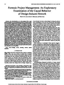
Chapter 3 MEDEVAC Domain Object Model The medical evacuation domain was modeled by selecting a subset of the DITOPS core concepts and specializing them for this problem. This chapter will present the object model developed for this domain. Standard DITOPS concepts are referred to but not documented here. The reader is referred to the previous chapter for a description of the standard DITOPS class library. The OMT diagram of figure 3.1 describes the object model of the medical evacuation domain. In this diagram, DITOPS core classes have their names in uppercase, while the medical evacuation domain classes (in essence, classes designed and implemented for this prototype) have their names in lowercase. The general structuring of the problem is as follows:
� The system expects five different types of input: (1) descriptions of patients to be transported, (2) a set of scheduled missions flown by a set of aircraft (possibly with some capacity already allocated), (3) a set of hospitals with specified medical specialties, (4) a set of airfields, with associated ASFs; finally, (5) disruptive events which modify the systems representation of the world and have to be reacted to.
� The system will perform both generative and reactive scheduling.
In the generative mode, routes (itineraries) are created for each unscheduled patient. In the reactive mode, disruptions in the existing schedule are being reacted to by repairing the schedule.
The general modeling approach taken can be described as follows:
� Patients are modeled as demands, incoming orders to the system. 11
TRANSPORT-LOAD
EARLIEST-LATEST-MIXIN
TRANSPORT-OPERATION
patient-load
MONOTONIC-TBP-MIXIN
resource AGGREGATE-RESOURCE
LOCATION itinerary BATCH-RESOURCE
medical-facility MOVABLE-RESOURCE-MIXIN airfields mtf medical-specialties asf
mtfs
airfield asf MOVE-REQUIREMENT
airfield
mission
sub-operations
geoloc-code airfield-name longitude latitude
missions
mission-leg origin
id medical-or-cargo aircraft
depart-time arrival-time
velocity
resource
destination
patients
legs
patients
BEFORE patient urgent-p medical-specialty-required real-name prescribed-destination-reason hours-before-ron
medical-treatment
mission-legs
resource relations
patients
leg-connection
patient-leg-connection
Figure 3.1: MEDEVAC Model OMT Diagram
� Aircraft are modeled as batch resources (multiple-capacity resources with time-synchronized execution). They are also “movable”, meaning that they keep track of their geographical position.
� Airfields, Medical Treatment Facilities and Air Staging Facilities are modeled
as aggregate resources (multiple-capacity resources with no requirement for time-synchronized execution).
� Missions, mission legs and medical treatment operations are modeled as trans-
port operations. These operations potentially change the position of their executing resource (such as an aircraft).
� Constraints between mission legs (both from the missions’ standpoint and
from the patients’ standpoint) were modeled as types of before temporal relations.
It should be noted that contrary to the normal approach of scheduling operations formed as a response to receiving demands (orders), the scheduling process in this prototype has been organized somewhat differently: operations are already scheduled (missions, mission legs), and the role of the scheduler is to find suitable combinations of operations (routes) to satisfy as many demands as possible as well as possible. This can be seen as the mission legs in essence being resources, since they impose allocation constraints on the “real” resources, the aircraft.
12
3.1 Object Model Description This section supplements the OMT diagram at the beginning of the chapter and will give a detailed description of all modeling concepts of the prototype. The documentation style mimics that of the book “Common Lisp: the Language” [6, in particular see section 1.2.5]. Due to the fact that the implementation uses an extension of CLOS called “PORK” [1], the notation has been extended to include inverse relations, automatically updated pairs of slots (indicated with the symbol) used to implement 1-to-1, 1-to-many and many-to-many relations.
$
[Class] [Initarg] [Initarg] [Initarg] [Initarg] [Initarg] [Relation] [Relation]
patient :urgent :medical-specialty-required :real-name :prescribed-destination :hours-before-ron relations patients mission-legs patients
$
$
This class inherits directly from move-requirement. Instances of this class represent patients to be moved, and are received by the system as input data. The slot urgent is a boolean value specifying whether the patient is urgent or regular. The slot medical-specialty-required specifies the particular constraints the destination MTF has to satisfy. The slot hours-before-ron holds the maximum number of hours a patient can fly before an overnight rest (at an ASF) is required (the slot defaults to 12 hours). [Class] [Initarg]
aircraft :velocity
This class inherits directly from batch-resource and movable-resourcemixin. Instances of this class represent individual aircraft used for transporting patients. The slot velocity gives the speed of the aircraft used when estimating the flight time between airfields. [Class] [Initarg] [Initarg] [Initarg] [Initarg] [Initarg] [Initarg] [Relation]
airfield :geoloc-code :airfield-name :longitude :latitude :missions :patients mtfs airfield
$
13
asf
$ airfield
[Relation]
This class inherits directly from aggregate-resource and location. Instances of this class represent airfields, with associated MTFs and possibly an associated ASF. Each airfield maintains a list of mission legs departing from that airfield, in the order of their departure time (slot missions). These mission legs link airfields in a web of possible routes that is used when searching for feasible routes for patients. [Class]
medical-facility
This class inherits directly from aggregate-resource. Subclasses of this class include mtf and asf. Instances of this class are used as resources for operations of class medical-treatment. asf :airfield airfield
$
[Class] [Initarg] [Relation]
asf
This class inherits directly from medical-facility. [Class] [Initarg] [Initarg] [Relation]
mtf :airfields :medical-specialties airfields mtfs
$
This class inherits directly from medical-facility. [Class] [Initarg] [Initarg] [Initarg]
itinerary :origin :destination :resource
This class inherits directly from transport-operation and monotonictbp-mixin. Subclasses of this class include mission-leg and mission. This is the base class for all mission and patient itinerary components. No special functionality has been defined for this class. The slots origin, destination and resource (from transport-operation) hold the origin and destination airfield resources as well as the aircraft resource used. [Class] [Initarg] [Initarg]
mission :id :medical-or-cargo
This class inherits directly from itinerary. Instances of this class are aggregate operations which represent entire missions. The relationship between a mission instance and its constituent mission legs is implemented using the 14
children relation of DITOPS’ operation class (in other words, mission legs are children to a mission which in turn is the parent of the mission legs). The slot id is a unique identifier for the mission. The slot medical-or-cargo identifies the mission as either a dedicated medical evacuation mission or an existing cargo mission having capacity for patient “cargo”. [Class] [Initarg] [Initarg] [Initarg] [Relation]
mission-leg :depart-time :arrival-time :patients patients mission-legs
$
This class inherits directly from itinerary. Subclasses of this class include medical-treatment. Instances of this class represent individual “steps” of a mission. The slot depart-time contains the scheduled start time of the particular mission leg, similarly the slot arrival-time contains the scheduled end time of the leg. The relation patients contains all patients scheduled to fly on this leg. [Class]
medical-treatment
This class inherits directly from mission-leg. Instance of this class represent a patient’s treatment at a medical facility. [Class]
patient-load
This class inherits directly from transport-load and earliest-latestmixin. Instances of this class are sub-operations of mission-leg operations. They represent the loading and unloading of patients to aircraft. [Class] [Initarg] [Relation]
leg-connection :patients patients relations
$
This class inherits directly from before. Subclasses of this class include patientleg-connection. Instances of this class represent connections between mission legs. They are used as temporal constraints (precedence constraints) by the Time Bound Propagator component of DITOPS. The relation patients contains all patients whose itinerary includes this connection. [Class]
patient-leg-connection
This class inherits directly from leg-connection. Instances of this class represent plane-change connections in patients’ itineraries. Note: constraints of class 15
leg-connection represent intra-mission connections, whereas patient-legcon-nection constraints represent inter-mission connections.
16
Chapter 4 Problem-Solving Architecture This chapter documents the DITOPS problem solving architecture and how it was adapted for the medical evacuation domain. Scheduling in DITOPS is formulated as a reactive process, reflecting the fact that a schedule at any level or stage of the deployment planning process is a dynamic evolving entity, and is continuously influenced by changing mission requirements, conflicting decision-making perspectives/goals and changing executional circumstances. This problem solving perspective in large part motivates the aforementioned representations of changing resource state over time (i.e., available capacity, location). These representations are pre-requisites to the specification of procedures for reflecting the consequences of changed constraints and for incrementally managing schedules in response to such changes. Schedule generation and revision at a given level of detail is uniformly cast as an opportunistic process that (potentially) selectively employs a number of distinct scheduling methods. Methods defined in the core DITOPS implementation include general-purpose procedures for "resource" and "movement" oriented scheduling. These methods are derived from the original multi-perspective concept of OPIS and are capable, respectively, of generating/revising the scheduling decisions of a given set of resources or a given set of temporally related movements. A set of more specialized schedule revision methods is also available, providing alternative resolution capabilities in situations of constraint conflicts. All methods share a common search infrastructure, which includes both (1) machinery for incrementally propagating the consequences of scheduling decisions and detecting constraint conflicts, and (2) search space elaboration primitives that support dynamic "batching" and "splitting" of move requirements in situations where the resource capacity constraints of alternative transportation assets dictate. The choice of which set of scheduling decisions to focus on next and which method to apply, at any point during the scheduling or rescheduling process, is based on heuristics that relate 17
characteristics of current solution structure to the optimization and resolution strengths of alternative methods. Several of DITOPS’ scheduling methods are implemented by specializing or instantiating an abstract search class. Among the available specializations of this class is a class that implements a beam search algorithm. The beam search class provides a customizable, heuristic search procedure which allows easy configuration of search state expansion and search direction. Search state expansion is done using a set of programmer-defined search operators, whereas the search direction is customizable using a programmer-defined evaluation function. The DITOPS control architecture is a specialization of an abstract class based on the blackboard control mechanism. This mechanism organizes and coordinates the actions of several heterogeneous problem-solvers or methods (also called knowledge sources). The control mechanism itself is a specialized knowledgesource called Top Level Manager which encapsulates all the functionality to deal with the control of the system’s problem-solving behavior. The knowledge sources define the strategic alternatives available to the system to solve some specific problem. For each particular instantiation of the control architecture, domain specific problem solvers will be added and the control cycle behavior will be customized accordingly. For example, in the medical evacuation domain, the architecture presumes the existence of a set of domain specific knowledge sources that can be used to generate, analyze, and revise patient allocations and mission itineraries. The Top Level Manager operates on events and tasks. Events are internal and external stimuli to the system: any action the user performs through the user interface is considered an external event or external disruption; external events are mapped onto the solution state generating internal events. The events characterize the current state of the schedule identifying the relevant control information. Control heuristics are used to aggregate, sort and process these events. The problem-solving proceeds via the formulation of tasks as responses to specific events. The tasks generated as a result of processing the events are then prioritized and processed by the knowledge sources. These tasks can perform analysis, generation or revision of the schedule. The Top Level Manager keeps a list of pending tasks. This list constitutes the current plan for solving the scheduling problem. Depending on the type of the task, the Top Level Manager selects the most appropriate knowledge source to process. Changes in the state of the schedule resulting from the execution of other knowledge-sources is also communicated to the Top Level Manager via posting of events. The higher levels of the hierarchy of objects manipulated by the Top Level Manager are defined as:
18
event
opportunity conflict hypothesis-modification task top-level-task analysis-task scheduling-task knowledge-source top-level-manager analyzer scheduler The instantiation of the DITOPS problem-solving architecture for the medical evacuation domain is composed of five knowledge sources: the Top Level Manager – responsible for the control cycle; the Model Update that translates external disruptions into internal events; the Analyzer that identifies and collects information about the conflicts in order to suggest the most adequate problem solving behavior; the Route Planner which fixes inconsistent mission routes; and the Patient Scheduler which allocates patients to available missions and guarantees that all patients have complete and consistent itineraries. The knowledge sources are invoked based on the conflicts introduced as a result of disruptive events. The basic control cycle works as follows: 1. In response to changes in the real world, the user introduces disruptions into the system through a graphical user interface. See chapter 5 for more details about external disruptions. 2. Disruptions are classified by type and objects that are affected. The Model Update knowledge source is then triggered or called to update the internal representation of the solution. During the model update phase, internal events are generated. Some events denote conflicts or inconsistencies and will require some correction to be performed; others are just a signal that something has changed. 3. Events are then prioritized according to type and severity. 4. After the prioritization of events, the most urgent events are selected and an analysis task is formulated. 5. The analysis task is processed by the Analysis knowledge source. This knowledge source will identify if the events represent conflicts that need some corrective action and what is the most appropriate problem solver to perform the correction. 6. A problem-solving task is formulated based on the results of the analysis.
19
7. An appropriate knowledge source is invoked to execute the newly formulated task. 8. If conflicts remain (or more were introduced), loop to 3. In the next sections we will present the general behavior of the two problem solvers. The rationale for the analysis knowledge source and the details of how each disruption is treated are presented in chapter 5.
4.1 Route Planner Knowledge Source The purpose of the Route Planner knowledge source is to fix missions which have been rendered inconsistent as a result of introducing changes (as a response to disruptive events). Inconsistencies can be temporal (successor leg departs before predecessor leg has arrived) or geographical (successor leg departs from a different airfield where the predecessor leg ended). The set of missions initially available is considered to be known beforehand. The route planner will not be used in the generative mode: it does not generate missions to satisfy the patients requirement; it only fixes existing missions if the analyzer identifies that the disruptions introduced inconsistencies affecting the current set of missions. When scheduling patients, the system assumes that all missions in the system are temporally and geographically consistent. The general behavior of the route planner is to remove conflicting legs from a mission and add new ones. According to the type of conflict, two different strategies are implemented:
� If there is a gap in the sequence of legs, that is, if there is a pair of airfields
in the itinerary of the mission that is not connected by any leg, the system will generate a new leg filling the gap and will add this leg to the mission. If the new leg introduces temporal constraint violations, that is, the new added leg finishes before the next leg in the sequence, the remaining legs will be shifted by the required amount. The patients involved in the conflict and identified during the analysis process are allocated to the new leg. This strategy is used, for example, when an intermediate airfield of a mission is closed. In this particular case, the closed airfield will be bypassed and all patients allocated in the arriving leg that got cancelled will be sent to the new destination.
� If there are no gaps in the sequence of airfields served by a mission but the
last destination is not available, the last leg of the mission will be removed 20
and a new leg having as destination an airfield as close as possible to the old destination will be introduced. All patients of the cancelled leg are transferred to the new created leg. This strategy is useful, for example, when the final airfield destination of a mission is closed when the aircraft is already en route to the closed airfield. A third strategy that could be easily implemented is adding new legs to existing missions. This strategy would be useful in the case of resource breakdown requiring emergency landing or to pick up patients in locations not served by any missions. In this case, the user would have to specify insertion points in the mission itinerary for the new legs and respective destinations. This knowledge source does not deals with patient’s conflict. It will perform the default behavior of allocating the affected patients in the added legs. The occurrence of new conflicts will be verified and signaled. The analyzer will be responsible for identifying whether previous conflicts are still valid after the mission has been fixed.
4.2 Patient Scheduler Knowledge Source The purpose of the Patient Scheduler knowledge source is to find feasible routes for patients and to schedule them, producing patient itineraries. The Patient Scheduler allocates patients to existing missions, ASFs, and MTFs by searching for feasible routes in the airport/mission-leg network (described earlier). This knowledge source uses a specialization of DITOPS’ beam search algorithm to perform a geographical search of feasible routes and potential destinations. At any particular airport, the search tree is expanded to those airports which are targeted by a temporally feasible mission leg. Each destination is checked for the existence of the required medical facility and a check is also made that to verify if the destination is not already part of the patient’s itinerary, to avoid “loops.” If the patient’s itinerary exceeds a certain number of hours, a rest-overnight using an ASF is added to the itinerary. When an airfield with the required medical facility is reached, a medical treatment operation using the MTF facility is added to the patient’s itinerary. The search can be parametrized by defining the beam width, the maximum accepted number of legs in a patient’s itinerary, and the maximum number of hours an itinerary may have. If a search tree violates some of these limits or if there are no missions that can satisfy the patient’s requirement the search will fail and return no itinerary for a patient. In this case, a one leg mission taking the patient from his origin to a destination with the required medical specialty will be added. If the patient requires a medical specialty that cannot be satisfied by any of the available hospitals, the 21
patient will not be allocated and an error message will be issued. The search is guided by a heuristic evaluation function that uses a weighted combination of several different user-defined preferences. In the examples we created, we were using preferences that minimize: Travel time: number of hours from the ready date to the arrival at the hospital. Number of legs: total number of connections and rest overnight. Arrival time: the time the patient arrives to the medical facility. Departure time: the time of the first flight since the patient is ready. The relative importance of these evaluation function components is configurable by the user and can be changed dynamically according to the evolving situation. The search algorithm can be described as: 1. Initialization: Set ORIGIN, START-TIME and MEDICAL-SPECIALTY to the origin, ready-date and medical specialty required by the patient respectively. Add ORIGIN to ITINERARY. 2. IF ORIGIN has hospital with MEDICAL-SPECIALTY, reserve hospital and return ITINERARY. By reserve hospital we mean create a medicaltreatment operation that reserves the hospital for the patient. 3. ELSE IF flying-time > MAX-FLYING-TIME or number-of-legs > MAXNUMBER-OF-LEGS return EMPTY. MAX-FLYING-TIME is the maximum total flying time allowed and MAX-NUMBER-OF-LEGS is the maximum number of legs allowed in a patient’s itinerary. 4. ELSE IF flying-time > MAX-HOURS-BEFORE-RON, reserve ASF and add rest-over-night operation to ITINERARY. MAX-HOURS-BEFORE-RON is the maximum time a patient can fly before she/he needs to rest for a certain period of time in an ASF facility. 5. ELSE set LEGS to the set of all legs leaving ORIGIN such that leg-start-time START-TIME and the leg destination is not part of ITINERARY.
�
(a) IF LEGS is not empty i. ii. iii. iv.
Set ORIGIN to the leg destination Set START-TIME to the leg end-time. Add ORIGIN to ITINERARY GOTO step 2 22
(b) ELSE return EMPTY 6. If search returned EMPTY do: (a) Create a new one leg mission going from patient origin to the closer airfield that has an MTF with the required medical specialty. (b) Set ORIGIN to the destination of the added mission. (c) Add ORIGIN to ITINERARY (d) GOTO step 2 The algorithm described above will take any origin and any medical specialty and will always find a feasible itinerary provided there is at least one MTF with the required medical specialty. As a consequence of this, the same algorithm can be used in the generative and reactive case. In the reactive case, we assume there is an inconsistency in the patient’s itinerary. This inconsistency can be overlapping legs, a missing MTF, or gaps in the sequence of destinations. The analysis method verifies the patient’s itinerary and identifies the consistent part of it if there is any. The Patient Scheduler removes the inconsistent part, maybe the complete itinerary, and generates a new consistent itinerary from the last reachable destination. The automatic addition of missions is a feature that is not always desired since the system assumes that resources are available and that missions can be created at any time. To overcome this problem, after the system finishes scheduling, it is possible to inspect and cancel all automatically added missions. When canceling added missions, all the patients allocated on that missions will be completely unscheduled. The user can then add new missions and try to allocate the now unscheduled patients. The system also provides the feature of unscheduling patients one at a time, unscheduling all late patients, or unscheduling all patients.
23
24
Chapter 5 Reactive Capabilities This chapter will describe the different types of “disruptions” or disruptive events the reactive planner is capable of handling. By disruption we mean any action performed by the external user that will change the internal state of the system and will, eventually require some reactive or corrective behavior. We assume that all disruptions are introduced through the graphical user interface. For example, to introduce new patients in the system, the user has to load a file with the patient descriptions; these descriptions will be translated into internal objects. The creation of these objects tells the system that some disruption has occurred. In response to the disruption, the patient router will be triggered or executed to schedule the patients. In this sense, all the system behavior can be considered reactive, the generative behavior being only a special case. The basic reactive mode of operation can be divided into three clearly defined steps:
� Introduction of a disruptive external event. The user, through the Graph-
ical Interface, communicates to the system that changes have occurred in the real world. The types of disruption accepted are: new patients, mission delay, mission cancelled, patient goes sour, aircraft breakdown, and airport closed.
� Once the disruption is introduced, the system updates the internal state
of the current solution. This involves the translation of the external event into changes in the schedule representation. For each type of disruption, some unconditional changes will be introduced. These unconditional changes represent the modeling assumptions on how the state of the system evolves in response to specific disruptions. The process of changing the state of the solution may cause conflicts or inconsistencies that are signaled by the system. Conflicts are signaled as a consequence of one or more constraint violations and are classified according to the type and 25
severity of the violation. Even if no constraint has been violated, the system will still signal that an external disruption has occurred since some action can eventually be performed to improve the solution.
� In response to internal events being signaled, the problem-solving control
architecture is invoked. The problem-solving mechanism cycles through a series of knowledge intensive actions on the set of pending events. These actions aims at identifying and performing the best possible correction and include event aggregation, event selection, event analysis, and conflict solution. The analysis process will acquire all the available information about the conflict and, based on its knowledge about available problem solving methods, suggest some corrective actions. Notice that no modification on the state of the solution is introduced in the analysis phase. The problem-solving methods are then selected based on a combination of user preferences and analysis results. These methods, also called knowledge-sources are the ones that will actually change the solution in order to resolve the conflicts.
5.1 Disruptive Events This section will present more details about the previously mentioned three steps for each type of disruption. Currently the system is capable of handling six basic types of disruptive events: new demands, patient goes “sour”, delay mission, cancel mission, aircraft breakdown, and airfield closed. For each type of disruption, there is a set of assumptions that corresponds to the underlying model on which the system is based. These assumptions are used to implement a set of primitives actions used by the model update phase of the solution. The external disruptions map into a set of primitive update actions: delay mission-leg and cancel mission-leg. During the execution of these update actions, conflicts are identified and signaled. After the conflict analysis, conflictsolution primitives are executed until the system is in a consistent state. The conflict solution primitives are schedule patient, unschedule patient, and add mission-leg. The action of the conflict-solution primitives can also introduce new conflicts that will be identified and solved in a similar way. The problem solving cycle will stop when the solution is in a state in which all missions and scheduled patients have valid and no-conflicting routes: there are no gaps and no time overlaps in the routes and patients have the required support facilities added to their itinerary. Figure 5.1 summarizes the relation between external disruptions, model-update primitives, and problem-solving primitives. The detailed behavior for each type of disruption is presented in the following 26
Cancel Mission
Cancel Leg
Airport Closed
Schedule Patient
Aircraft Breakdown
Delay Leg
Delay Mission
Add Leg
New Patient
Unschedule Patient
Patient Sour
External Disruptions
Model Update
Problem Solving
Figure 5.1: Disruption Summary paragraphs (screen dumps depicting various disruptions and their resolution are included as an appendix):
� New Patients Introduced
New patients are added to the system by loading a file containing all the patient information. After the file has been loaded, the fact that there are unscheduled requests in the system will trigger the problem-solving control cycle. The system will try to allocate patients using the set of existing missions. Each scheduled patient will have an itinerary composed of mission-legs, that correspond to the allocation on airplanes, and medical treatments, that correspond to allocations in ASFs and MTFs. The general allocation behavior is: if there are feasible missions, patients are allocated on these; if not, and the new patients are “urgent”, routine patients are “bumped” off their existing itineraries/flights to make room; if no other solution is possible, new (one-leg) missions are created. Existing missions are not modified. The new missions introduced by the system will take the patient from its origin to a destination with the required medical facility. If the user does not want the added missions, they can all be cancelled or cancelled on a case by case basis. The itineraries of the “bumped” patients are dealt with on a case by case basis. Rest-over-night on ASFs are introduced in the patient itinerary after the patient has flown a certain number of hours. Figure A.1 shows the system just after new patients have been loaded. All missions are empty and patients are unscheduled. 27
Origin
Dest.1
Dest.2
t2
t3
Dest.1
Dest.2
t2
t3
1. t1
Origin
2. t1
Patient Goes Sour
Origin
Dest.1
Dest.2
t2
t3
3. t1
Figure 5.2: Patient Goes Sour During Intermediate Leg Origin
Dest.1
Dest.2
t2
t3
Dest.1
Dest.2
t2
t3
1. t1
Origin
2. t1
Patient Goes Sour
Origin
Dest.1
Dest.2
t2
t3
3. t1
Figure 5.3: Patient Goes Sour During Final Leg Figure A.2 shows the system after patients have been scheduled. The patients use the aircraft capacity and the system indicates that some patients are late by using different colors to represent late patients.
� Patient Goes “Sour” During Flight
The patient is removed from the plane (and from the system) at the next stop. We assume that the time the patient goes sour is specified. If the patient goes sour in the last leg of its itinerary, nothing will happen – the patient will go to the medical facility as a regular patient. No conflict is generated and no reaction is performed by the system when a patient goes sour. Figure 5.2 shows what happens when a patient goes sour during an intermediate leg and figure 5.3 shows what happens when it is the finale leg. Figure A.3 shows the graphical display for a patient’s itinerary before 28
Origin
Dest.1
Dest.2
t2
t3
Dest.1
Dest.2
t2
t3
1. t1
Origin
2. t1
ts = Delay Start Time D = Delay Duration
Origin
Dest.1
3. t1
t2
Dest.1
t2 + D
Dest.2
t3
D
Figure 5.4: Mission Delay she/he goes sour. Figure A.4 shows the itinerary of the same patient after she/he goes sour. Notice that the part of the itinerary after the start time of the event is removed from her/his route.
� Mission Delayed
We assume we know in advance the start time and expected duration of the delay. This type of event is translated into a set of delayed mission legs. The unconditional behavior of delaying a mission is that all legs starting after the beginning of the delay will have their start times shifted beyond the end of the delay. The legs that have a start time before the beginning of the delay are not changed. Mission delay will only introduce conflicts on the patient itineraries. Depending on the size of the delay, some patients will probably lose their connections. The system identifies all patients that would lose connecting flights and generates for each patient a new itinerary starting from the airfield she/he lost the connection. No complete rescheduling of patients will occur unless requested by the user. Figure 5.4 shows the general behavior for delaying a mission. Figure A.5 shows a mission before the delay and A.6 shows the same mission after the delay. Notice how the mission-legs are right shifted and all patients are kept in the legs.
� Mission Canceled
We assume we know in advance the cancellation start time. The unconditional behavior is that all remaining legs of the mission are canceled. A mission leg that starts before but ends after the cancellation time, is 29
Case 1. Leg Not In Process Origin
Dest.1
Dest.2
t2
t3
Dest.1
Dest.2
t2
t3
1. t1
Origin
2. t1
ts = Cancellation Time
Origin
Dest.1
Dest.2
t2
t3
3.
t1
Figure 5.5: Cancel Mission – Leg not in process
Case 2. Leg in Process Origin
Dest.1
Dest.2
t2
t3
Dest.1
Dest.2
t2
t3
1. t1
Origin
2. t1
ts = Cancellation Time
Origin
Dest.1
Dest.2
t2
t3
3.
t1
Dest. 3
ti
Figure 5.6: Cancel Mission – Leg in process
30
Origin
Dest.1
Dest.2
t2
t3
Dest.1
Dest.2
t2
t3
1. t1
Origin
2. t1
Airfield Closed Origin
Dest.1
Dest.2
t2
t3
3. t1
Airfield Closed
Origin
Dest.1
Dest.2
4. t1
t2
t3
Airfield Bypassed
Figure 5.7: Intermediate Airfield Closed also cancelled. The cancellation will always generate an event to tell the system that a mission has an inconsistent itinerary. If no patients have been scheduled in the legs cancelled, no other conflict is generated and no problem-solving is needed besides the legs cancellation. If there are patients scheduled, the itinerary of each patient allocated to the legs cancelled will have a gap or will be incomplete. In this case, the system will also signal the inconsistency on patient’s itineraries. If the mission is cancelled with a leg already in process, as for example when the destination airfield is closed, the analysis process will identify the need of correcting the leg in-process and a problem-solving method will be triggered to fix the mission leg. The default strategy in this case is to reroute the leg to an airfield closer to the previous destination. The correction of the mission leg takes precedence over the correction of patient’s itinerary. After the mission has been fixed, the conflicts concerning patients will be analyzed and the itineraries will be fixed. Figure 5.5 shows schematically the cancelling of a mission when the leg is not in process and figure 5.6 shows the cancelling of a mission with the leg already in process. Figure A.7 shows the mission before cancellation and figure A.8 shows the mission after cancellation. All legs after the start time of the cancellation are removed from the mission and patients are rescheduled later.
� Airfield Closed
All affected mission legs are either delayed or canceled, the missions are repaired, and patient itineraries are repaired on a case by case basis. 31
Origin
Dest.1
Dest.2
t2
t3
Dest.1
Dest.2
1. t1
Origin
2. t1
t2
t3 Airfield Closed
Origin
Dest.1
Dest.2
3. t1
t2
t3 Airfield Closed Leg NOT in process
Origin
Dest.1
Dest.2
4. t1
t2
t3
Figure 5.8: Final Destination Airfield Closed – Leg not in process Several special cases exist for mission repair: (1) If the affected airfield is an intermediate stop on a mission, the legs flying into and out of this airfield are unconditionally canceled. A conflict will be generated and the analysis process will identify that there is a gap in the itinerary of the mission. A problem solving method will be executed to fix the mission. The default behavior in this case is to add one new leg to fill the gap. In this way, the closed airfield will be bypassed. The patients scheduled on the removed mission legs will be allocated in the new added leg. After the mission has been fixed, the patients itinerary will be fixed. Figure 5.7 shows the closing of an intermediate airfield. Figure A.9 shows a mission leg that uses an intermediate airfield. After the closing of the airfield and fixing the mission, figure A.10 shows that the mission now bypasses the closed airfield. (2) If the closed airfield is the final destination of a mission, the last leg is unconditionally cancelled; if the leg is already in progress, the analysis process will identify the problem and a problem solver will be called to fix the mission. The default behavior in this case will be to add a new leg having as destination an airfield closer to the closed airfield. All patients in the cancelled leg will be allocated in the new leg. After the mission is fixed, patients itineraries will be analyzed and fixed if necessary. Figures 5.8 and 5.9 show the closing of an airfield that is the final destination: in the first case, the mission-leg is not in process so no mission fixing is required. Patients’ itinerary will need corrections. In the second case, the last leg is already in process: the leg is cancelled, a new leg is added, all patients are in the new leg. (3) If the closed airfield is the first one on a mission, the entire mission is delayed until the airfield opens again. This is the same behavior as 32
Origin
Dest.1
Dest.2
t2
t3
Dest.1
Dest.2
1. t1
Origin
2. t1
t2
t3 Airfield Closed
Origin
Dest.1
Dest.2
3. t1
t2
t3 Airfield Closed Leg IN PROCESS
Origin
Dest.1
Dest.2
4. t1
t2
t3 Dest. 3
t4
Figure 5.9: Final Destination Airfield Closed – Leg in Process
Origin
Dest.1
Dest.2
t2
t3
Dest.1
Dest.2
t2
t3
1. t1
Origin
2. t1
t1 + D
Airfield Closed
Origin
Dest.1
Dest.2
3. t1 + D
t2 + D
t3 + D
Figure 5.10: Mission Origin Airfield Closed
33
Origin
Dest.1
Dest.2
t2
t3
Dest.1
Dest.2
t2
t3
1. t1
Origin
2. t1
Resource Breakdown
Origin
Dest.1
3.
t1
t2 Dest.1
t2 + D
Dest.2
t3 + D
D
Figure 5.11: Aircraft Breakdown with Mission in Process delaying. Figure 5.10 shows the mission delay when the origin airfield is closed. The default behavior implemented in each particular case can be change by specifying different strategies. For example, we could establish that we want a new stop instead of bypassing a closing intermediate airfield or that we want the aircraft to return to its last departure airfield when the final destination gets closed with the mission in progress.
� Aircraft Breakdown Introduced
This is similar to mission delay. If the problem occur during the execution of a leg, the aircraft lands at the correct destination of the in-process leg, after which all legs are delayed (again we assume the existence of a duration estimate for the problem). Patient itineraries are repaired on a case by case basis. An alternative behavior will be to add a new stop to the mission. The aircraft problem is presented in figure 5.11. Figure A.11 and A.12 presents the mission before and after the aircraft problem.
After the introduction of disruptive events and their translation to the internal problem representation a set of conflicts exists (e.g. patients missing their connection because of a delayed flight etc.). The problem-solving architecture is called to repair the schedule (i.e., to resolve these conflicts). The problemsolving architecture is also responsible for ensuring that all missions are temporally and causally consistent (for example, a leg cannot depart before the previous leg has arrived, and can only depart from the airfield where the previous leg ended). Mission fixing takes precedence over patient’s itinerary fixing 34
because the patient scheduler assumes that all mission in the system are consistent. As was mentioned before, the solution state update after a disruption and the subsequent problem solving techniques used are based on our assumptions of the model. It is easy to change the default behavior to comply to more accurate user requirements or more refined models. All disruptions introduced are signaled, even if they do not introduce any changes in the solution. The system keeps track of all disruption events and changes caused by them. Reports summarizing the disruptions and affected objects can be generated at any time.
35
36
Chapter 6 Conclusions The goal of this project was to demonstrate the applicability of the DITOPS scheduler to the problem of reactive re-planning in the medical evacuation domain. We believe that this goal has clearly been achieved. In a relatively short period of time, a quite sophisticated planner was designed and built. The planner incorporates important domain constraints and assumptions (e.g., multi-leg patient itineraries, finite transport capacity, finite in-transit (ASF) and destination (MSF) medical treatment capacity), is capable of revising medical evacuation plans in response to a substantial set of disruptive events, and appears directly scalable to full-scale evacuation problems and scenarios. The planner provides strong evidence of the utility of the modeling and scheduling componentry provided within DITOPS, and a compelling example of the efficacy of approaching application development as a differential process of component configuration and customization. This approach, in our view, is pre-requisite to cost-effective development of complex planning and scheduling applications. Evaluating the plans created by the DITOPS medical evacuation planner is not an easy task. The system generates and maintains feasible plans (modulo the system’s current constraint models). However, due to the unavailability of both realistic input data and comparative results from other medical evacuation planning systems, it has not yet been possible to systematically evaluate the system’s problem solving performance, or to determine how well the planner would do solving actual medical evacuation problems (the problems it has solved are only our understanding of what the real world is like). The next logical step in this research would be to conduct some sort of analysis of current system capabilities. One starting point could be comparison to current TRAC2 ES planning and replanning modules on benchmark problems such as the "Lilliput" scenario (this problem has been solved by the current prototype). Evaluation and feedback from the medical evacuation planners would also seem essential at this point. To facilitate such user involvement and evaluation, the current pro-
37
totype provides a graphical interactive framework for flexibly experimenting with various disruptive events and examining the results of reactive responses. One obvious direction for further development of the current medical evacuation planner would be to expand the range of constraints that are accommodated and enforced within the system’s domain model. Our initial effort has concentrated attention on an identified subset of "important" domain constraints. To be practically applicable, a re-planning capability would necessarily need to take into account additional aspects of the domain. Given our current understanding of the medical evacuation re-planning problem, we can identify several domain details and constraints that are ignored in the current prototype:
� Difference between cargo and medical missions. Distinguishing between these two would not be difficult to add.
� Range of aircraft missions. DITOPS models aircraft range but the range values are not used in this implementation; taking range into account when adding new missions/legs would be straightforward.
� Maximum flying altitude and other specific request for patients (like medical equipment and other requirements).
� Litter seats vs. ambulatory seats: all seats are considered to be the same. To implement this, DITOPS provides a mechanism for partitioning capacity of resources; in this case two partitions would be used.
� Different aircraft configurations have not been modeled. � Patients’ airfield preferences are not enforced (personal preferences like planning for the destination to be close to his/her home town etc.).
� Ground transportation is not provided. � Missions are not modified to pick up urgent patients. � Crew requirements are not modeled – the maximum flight time should be enforced by somebody else. We do not enforce any constraint on given missions besides spatial and temporal constraints.
� Compatibility aspects relating airfields and aircraft are not considered.
DITOPS has a mechanism called compatibility constraints which could be used to model this.
� Secondary resources (like fuel and food) are not modeled.
Another direction of future development would be the introduction of more sophisticated planning and scheduling strategies. The current medical evacuation 38
planner makes little use of underlying architectural capabilities for conditionalizing and integrating the use of different solution repair methods, but rather associates a particular repair method with each type of disruption or conflict. Consider, for example, the introduction of a mission delay, which in turn causes conflicts with respect to connecting flights in several patient itineraries. Currently, the planner resolves such conflicts by reassigning each affected patient to a new (feasible) connecting flight. However, there are tradeoffs that could be considered here. If a conflict involving a connecting flight is quite small (e.g., the flight is scheduled to leave just minutes too soon), then a much more reasonable reaction might be to simply delay the connecting flight. In general, there are opportunities for improved reactive planning behavior through increased analysis of the constraints involved in recognized conflicts and more selective use of constituent repair methods. Likewise, there are also straightforward extensions to the current set of methods which could provide a basis for more effective localized reaction in some circumstances. A version of the patient scheduler which allows selective "bumping" of currently scheduled patients (e.g., to allow the rescheduling of an urgent patient to displace a non-urgent patient if necessary) would be one obvious extension that is easily implemented.
39
40
Appendix A Screen Dumps This appendix contains screen dumps depicting the various disruptive situations described in chapter 5.
41
Figure A.1: New Patients in the System
Figure A.2: New Patients Scheduled 42
Figure A.3: Patient before going sour
Figure A.4: Patient after going sour 43
Figure A.5: Mission Before Delay
Figure A.6: Mission After Delay 44
Figure A.7: Mission Before Cancellation
Figure A.8: Mission After Cancellation 45
Figure A.9: Mission before closing an intermediate airfield
Figure A.10: Mission after closing an intermediate airfield 46
Figure A.11: Mission before aircraft breakdown
Figure A.12: Mission after aircraft breakdown 47
48
Bibliography [1] Lassila, O., “PORK Object System Programmers’ Guide”, Report CMURI-TR-95-12, the Robotics Institute, Carnegie Mellon University, Pittsburgh (PA), 1995. [2] Schmucker, Kurt. J, “Object-Oriented Programming for the Macintosh”, Hayden Publishing Company, Hasbrock Heights (NJ), 1986. [3] Stephen F. Smith and Ora Lassila, “Configurable Systems for Reactive Production Management”, Knowledge-Based Reactive Scheduling, IFIP Transactions B-15, North-Holland, Amsterdam (The Netherlands), 1994. [4] Stephen F. Smith and Ora Lassila, “Toward the Development of Flexible Mixed-Initiative Scheduling Tools”. Proceedings of the ARPA/Rome Labs Planning Workshop ’94, Tucson (AZ), February, 1994. [5] Smith, S.F.,“OPIS: A Methodology and Architecture for Reactive Scheduling”, in Intelligent Scheduling, (eds. M. Fox and M. Zweben), Morgan Kaufmann Publishers, 1993. [6] Steele, Guy L., Jr., “Common Lisp - the Language”, Digital Press, Bedford (MA), 1990. [7] Wirfs-Brock, Rebecca, Brian Wilkerson and Lauren Wiener, “Designing Object-Oriented Software”, Prentice Hall, Englewood Cliffs (NJ), 1990.
49