An Eyes-Free Vision-Based UPC and MSI Barcode Localization and Decoding ... one and one-to-zero transitions in a one pixel wide binarized bit string ...
An Eyes-Free Vision-Based UPC and MSI Barcode Localization and Decoding Algorithm for Mobile Phones Aliasgar Kutiyanawala Vladimir Kulyukin Computer Science Department Utah State University Logan, UT - 84322
1 Introduction Supermarkets are one of the most functionally challenging environments for visually impaired (VI) users. Accessible shopping systems can help VI individuals improve their quality of life by allowing them to shop independently. We are working on an accessible shopping solution called ShopMobile [1, 2] that will allow VI users to shop independently using only their cell phones. Most stores place MSI barcodes on shelves beneath each product for inventory control purposes. Since each barcode is unique, it acts as a topological landmark that can be used to localize the user in the store. Once the position of the user is known, verbal instructions can be generated and issued to the user using text-to-speech synthesis that will lead her to the desired product. The user can then pick up the desired product and scan the UPC barcode on it to verify that she had picked up the correct product. The current generation of smartphones are equipped with very good cameras and have powerful CPUs which enable them to be used as portable barcode scanners. However, most existing systems like ZXing [3] and RedLaser [4] can decode UPC barcodes but cannot decode MSI barcodes and require users to carefully align the barcode in the center of the image. An accessible barcode scanning algorithm described in [5] does not impose this restriction but is not implemented on a cell phone and cannot handle MSI barcodes. We present an eyes-free barcode localization and decoding algorithm that allows VI users to recognize MSI barcodes on shelves and UPC barcodes on packages.
2 Method 2.1 Interactive Camera Alignment To keep the vision algorithms simple and efficient, we require that the barcode is always aligned with the camera before taking a picture. Most products have UPC barcodes on the bottom of the package. To scan a barcode on a package the user finds the bottom of the package, aligns the camera with the side of the package and starts the interactive camera alignment loop by pressing a button on the screen. This causes the the current accelerometer readings in the pitch and yaw planes to be stored as reference. The user can now move the phone away from the surface of the package to take the picture. While the user is moving the phone, the accelerometer readings are monitored continuously and if the user deviates from the reference readings in either the pitch or yaw planes, specific haptic signals are sent until the camera is realigned with the package. The user stops moving the camera away when the camera is approximately 10cm from the surface of the package and takes a picture by clicking a button on the screen. This interactive camera alignment procedure ensures that the camera is always aligned (parallel or perpendicular) to the barcode.
2.2 Barcode Localization Algorithm The function of the barcode localization algorithm is to segment the barcode region from the image before passing it to the barcode decoding algorithm. A barcode is characterized as an image region having two properties – alternating frequency and vertical continuity. Alternating frequency is defined as number of zero-toone and one-to-zero transitions in a one pixel wide binarized bit string representation of an image. Vertical continuity is defined it as the continuity of black and white lines along the y-axis. Consider two one-pixel wide lines A and B placed over the barcode as shown in Figure 1. consider two one pixel wide lines A and B placed on the barcode as shown in the left part of Figure 1. These lines can be encoded as bit strings where black pixels map to zeros and white pixels map to ones. The alternating frequencies of the two lines can be found out by counting the number of zero-to one and one-to-zero transitions in the bit strings. The vertical continuity can be estimated as the length of the longest common subsequence between the two bit strings.
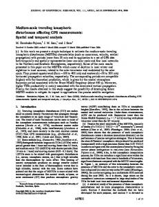
Figure 2 shows an overview of the barcode localization algorithm. The image is first passed through a line filter to filter out elements like graphics and text in the image. This filter is designed to let vertical lines in the image pass through and filter everything else. The output of this filter will contain the barcode and some vertical lines from other image elements. The filter output is then scanned rapidly in a rasterized fashion to score areas for alternating frequency and vertical continuity. Fast histogram analysis is then used to isolate areas exhibiting high alternating frequency and high vertical continuity. These areas represent candidate barcode regions and are sent to the barcode decoding algorithm for decoding.
Figure 1. One Pixel Wide Lines on the Barcode.
Figure 2. Barcode Localization Algorithm.
2.3 Barcode Decoding Algorithm The barcode decoding algorithm is responsible for decoding the barcode in the localized image. Our barcode decoding algorithm is scanline based. The scanline based algorithm described in [6] uses Bayesian templates for decoding barcodes and the one described in [7] uses deformable templates to decode barcodes. A scanline represents a one-pixel wide slice of the image. It is analogous to drawing a line on the image and extracting the pixels that lie below this line. The first step in our algorithm is to extract the data from the image along a scanline. If the scanline is n-pixels long, this data can be represented by I = {i0, i1, …, in}, where ij represents the intensity or greyscale value of the jth pixel within the scanline and 0 ≤ ij ≤ 255. Figure 3 shows a graphical representation of a part of the intensity curve I. Let us assume that the mean intensity along the scanline is m = mean(i0, i1, …, in). Consider two points on the intensity curve that are on either side of m (points A and B in Figure 3) and construct a line l that connects these two points. The intersection point p0 that represents the first intersection of curve I with line m can now be estimated with sub-pixel accuracy within the scanline as the intersection of line l with line m. The set of all the intersection points P = {p0, p1, …, pk+1} can be estimated in a similar fashion. The line widths W = {w0, w1, …, wk} can now be computed as wi = pi+1 – pi.
2.3.1 Decoding UPC Barcodes A UPC barcode [8] consists of 12 digits, arranged in two groups of six digits as follows: SDDDDDDMDDDDDDE, where S represents the start pattern, M represents the middle pattern, E represents the end pattern and D represents a digit. The start, middle and end patterns as well as each digit is encoded by a series of alternating
black and white lines of different widths as shown in Table 1. The total number of lines for a UPC code is 3 (start pattern) + 4 (per digit) × 12 (digits) + 5 (middle pattern) + 3 (end pattern) = 59 bars. To decode the barcode from the line widths W, we have to find the start pattern index (s) and the end pattern index (e) within W. The start pattern index and the end pattern index can be found as follows: s = argmax (wi-1 – std(wi, wi+1, wi+2)) and wi corresponds to a black pixel, e = argmax (wi+3 – std(wi, wi+1, wi+2)) and wi corresponds to a black pixel,.
Figure 3. Intensity Curve and Mean Intensity. The start pattern is encoded as three alternating black and white lines having unity width. Thus, if s represents the start pattern index, then ws, ws+1 and ws+2,will be approximately equal and the value of std(ws, ws+1, ws+2)) will be low. Also, the value of ws-1 will be high because it represents white space to the left of the barcode. Thus, the value of (ws-1 – std(ws, ws+1, ws+2)), will be maximum in W. Similar analysis can be applied to derive the value of the end pattern index. Digit/Pattern Template of Line Widths Start Pattern
111
End Pattern
111
Middle Pattern
11111
Digit 0
3211
Digit 1
2221
Digit 2
2122
Digit 3
1411
Digit 4
1132
Digit 5
1231
Digit 6
1114
Digit 7
1312
Digit 8
1213
Digit 9
3112
Table 1. Line Width Templates for Patterns and Digits within the UPC Symbology Since e represents the index of the end pattern, there are a total of 59 – 3 (for the end pattern) lines between s and e. Thus, further decoding of the barcode is proceeded only if e – s = 56. If we assume each line to be one pixel
wide, the sum of the widths for all the lines in the UPC code is 3 (start pattern) + 3 (end pattern) + 5 (middle pattern) + 7 (per digit) × 12 (digits) = 95. The set of line widths W can now be normalized by dividing it by 95. The index i of the jth digit dj in the width string can be easily calculated as follows: i = s + (i – 1) × 4, if j ≤ 6 and i = s + (i – 1) × 4 + 5, if j > 6 (add 5 lines for the middle pattern) Since each digit is encoded by four lines, the value of the dj can now be found out as follows: dj = argmin (Σ (wi+j – Tki+j)2)1/2, where 0 ≤ j < 4 and Tk represents the template of line widths for the jth digit as described in Table 1. The twelfth digit of the barcode represents the checksum of the preceding eleven digits and can be used to verify if the barcode was correctly decoded or not.
2.3.1 Decoding MSI Barcodes A MSI barcode [9] is a variable length barcode that is arranged as follows: SDD...DE, where S represents the start pattern, D represents a digit and E represents the end pattern. Table 2 shows the encoding of the start and end patterns as well as of digits 0 to 9 in the line widths format. The total number of lines in the barcode is equal to 2 (start pattern) + 3 (end pattern) + 8 (per digit) × n digits = 8n + 5. To decode the barcode from the line widths W, we have to find the start pattern index (s) and the end pattern index (e) within W. The start pattern index and the end pattern index can be found as follows: s = argmax (wi-1 - (Σ (wi+j – Tsj)2)1/2), where wi corresponds to a black pixel and 0 ≤ j < 2 e = argmax (wi+3 - (Σ (wi+j – TEj)2)1/2), where wi corresponds to a black pixel and 0 ≤ j < 3 TS and TE represent the templates of line widths for the start and end patterns as described in Table 2. Digit/Pattern Template of Line Widths Start Pattern
21
End Pattern
121
Digit 0
12121212
Digit 1
12121221
Digit 2
12122112
Digit 3
12122121
Digit 4
12211212
Digit 5
12211221
Digit 6
12212112
Digit 7
12212121
Digit 8
21121212
Digit 9
21121221
Table 2. Line Width Templates for Patterns and Digits within the MSI Symbology Since e represents the index of the end pattern, there are a total of 8n + 5 – 3 (for the end pattern) lines between s and e. Thus, further decoding of the barcode is proceeded only if e – s = 8n + 2. If we assume that each line in the barcode is one pixel wide, the total width of each digit is 12 pixels. Thus, the total width of the barcode is 3 (start pattern) + 4 (end pattern) + 12 × n (for n digits in the barcode) = 12n + 7 pixels.. The set of line widths W can now be normalized by dividing it by 12n + 7 (Assuming we know the value of n). The index i of the jth digit dj in the width string can be easily calculated as follows:
i = s + (i – 1) × 8 Since each digit is encoded by eight lines, the value of the dj can now be found out as follows: dj = argmin (Σ (wi+j – Tki+j)2)1/2, where 0 ≤ j < 8 and Tk represents the template of line widths for the jth digit as described in Table 2. The last digit of the barcode represents the checksum of the preceding eleven digits and can be used to verify if the barcode was correctly decoded or not. A modulo 10 checksum is most commonly used and it can be computed by the Luhn algorithm [10]. The above procedure shows how a scanline is decoded in the image. In practice, multiple scanlines are generated until a valid barcode is obtained. If a valid barcode is not obtained even after N scanlines have been decoded, it is assumed that the barcode may be perpendicular to the image. The original picture from the camera is rotated by 90 degrees once again subjected to the entire procedure of barcode localization and decoding.
3 Conclusion We have developed an eyes-free barcode scanning solution that can decode MSI barcodes on shelves and UPC barcodes on products.
References [1] Kulyukin, V., and Kutiyanawala, A., Eyes-Free Barcode Localization and Decoding for Visually Impaired Mobile Phone Users. Proceedings of the 2010 International Conference on Image Processing, Computer Vision, & Pattern Recognition (IPCV 2010), July 12-15, 2010, Las Vegas, NV. [2] Kulyukin, V., and Kutiyanawala, A., From ShopTalk to ShopMobile: Vision-Based Barcode Scanning with Mobile Phones for Independent Blind Grocery Shopping. Proceedings of the 2010 Rehabilitation Engineering and Assistive Technology Society of North America Conference (RESNA 2010), Las Vegas, NV. [3] The Zebra Crossing Barcode Decoding Library http://code.google.com/p/zxing/ [4] Occipital, LLC. RedLaser http://redlaser.com/ [5] Tekin, E. and Coughlan, J.M., An algorithm enabling blind users to find and read barcodes WACV09, 2009 [6] Tekin, E. and Coughlan, J.M., A Bayesian Algorithm for Reading 1D Barcodes, Proceedings of the 2009 Canadian Conference on Computer and Robot Vision , 2009 [7] Gallo, O. and Manduchi, R., Reading Challenging Barcodes with Cameras, Winter Vision Meetings, Workshop on Applications of Computer Vision, 2009 [8] Wikipedia, UPC barcode http://en.wikipedia.org/wiki/Universal_Product_Code [9] Wikipedia, MSI barcode http://en.wikipedia.org/wiki/MSI_Barcode [10] Wikipedia, Luhn algorithm http://en.wikipedia.org/wiki/Luhn_algorithm


![(Where to Buy==]] 'Code 39/MSI Barcode Font - Unlimited Distribution ...](https://m.moam.info/img/260x300/where-to-buy-code-39-msi-barcode-font-unlimited-di_647a37d9097c476a028c8b51.jpg)

![)Free Download~=]] 'Code 39/MSI Barcode Font - Single User' by ...](https://m.moam.info/img/260x300/free-download-code-39-msi-barcode-font-single-user_647a340d097c4769028c95e2.jpg)

![Free Download~=]] 'Code 39/MSI Barcode Font ... - WordPress.com](https://m.moam.info/img/260x300/free-download-code-39-msi-barcode-font-wordpressco_647a4719097c476b028cb59b.jpg)