An FPGA-based Torus Communication Network
arXiv:1102.2346v1 [hep-lat] 11 Feb 2011
DESY 11-011
Marcello Pivanti∗ INFN and University of Ferrara, Via Saragat 1, I-44100 Ferrara, Italy
[email protected]
Sebastiano Fabio Schifano INFN and University of Ferrara, Via Saragat 1, I-44100 Ferrara, Italy
[email protected]
Hubert Simma NIC, DESY, Platanenallee 6, D-15738 Zeuthen, Germany
[email protected] We describe the design and FPGA implementation of a 3D torus network (TNW) to provide nearest-neighbor communications between commodity multi-core processors. The aim of this project is to build up tightly interconnected and scalable parallel systems for scientific computing. The design includes the VHDL code to implement on latest FPGA devices a network processor, which can be accessed by the CPU through a PCIe interface and which controls the external PHYs of the physical links. Moreover, a Linux driver and a library implementing custom communication APIs are provided. The TNW has been successfully integrated in two recent parallel machine projects, QPACE and AuroraScience. We describe some details of the porting of the TNW for the AuroraScience system and report performance results.
The XXVIII International Symposium on Lattice Field Theory, Lattice2010 June 14-19, 2010 Villasimius, Italy ∗ Speaker.
c Copyright owned by the author(s) under the terms of the Creative Commons Attribution-NonCommercial-ShareAlike Licence.
http://pos.sissa.it/
Marcello Pivanti
An FPGA-based Torus Network
1. Introduction One of the key elements of a massively parallel computer is the communication network that interconnects the computing nodes. It allows the processes running on the CPU cores to cooperate as a large unique entity to solve computational problems fast. Parallel scientific computing often requires machines with tightly-coupled nodes, allowing applications, like Lattice-QCD or LatticeBoltzmann, to efficiently perform fine-grained communications and to scale in the strong regime, i.e. at constant problem size. Several massively parallel machines optimized for Lattice-QCD simulations have been developed by user-community projects, such as for example the APE systems [1] in Europe, and the machines of the Columbia University [2] in the US. Both developments have been based on a custom design of processor and network. To efficiently support the most relevant communication patterns of Lattice-QCD algorithms, a common choice for the network topology is a D-dimensional mesh (D = 3, 4, . . .) with periodic boundaries. The pairwise connectivity between (nearest-neighbour) nodes avoids the typical bottlenecks of switched networks and allows to scale machine performance to thousands of processes (until global reductions may become relevant). Modern commodity processor architectures, like x86 with SSE or Cell BE, can be efficiently exploited for LQCD computations [3, 4] and have low cost and power consumption per flop. The option of using off-the-shelf CPUs has lead to a new strategy in designing LQCD-optimized parallel machines, based on standard multi- or many-core processors interconnected by a custom network. This approach has been exploited in the QPACE [5, 6] and AuroraScience [7] projects. The torus network (TNW) which we have developed for these machines provides a simple but efficient interconnection network between multi-core commodity processors and can easily be ported to other architectures which support a standard IO technology, like PCI-express (PCIe), to interconnect CPU and network processor. Data transmission is based on a light-weight custom protocol with minimal overheads from operating system or software layers. The logics of the network processor is tailored to be implemented on recent Field Programmable Gate Array (FPGA) devices. This allows a quick and flexible development avoiding the risks and non-recurrent costs of an ASIC implementation. The hardware building block of both machines, QPACE and AuroraScience, is a compact node card which, apart from basic peripheral components, hosts the CPU(s), the RAM, and an FPGA with 6 external transceiver devices (PHY) to drive the 6 TNW links, each with a bit rate of 10 Gbit/s. In QPACE, each node is equipped with one IBM Cell processor (PowerXCell 8i) connected through the FlexIO bus with the FPGA (Xilinx Virtex-5 LX110T). The FPGA acts as south-bridge, Ethernet controller, and network processor for the torus network. The QPACE machines are integrated with a novel liquid cooling system and ranked as top entry of the GREEN 500 list in November 2009 and June 2010. The nodes of the AuroraScience machine are based on latest Intel multi-core CPUs. Each node has two six-core CPUs (four cores in the first version), 12 GByte of RAM. and a southbridge. It is connected to the FPGA (Altera Stratix IV GX-230) by two Gen2 8x PCIe interfaces, each providing an effective bandwidth of 3.2 GByte/s. In addition to the torus network, the nodes of AuroraScience are interconnected by a switched InfiniBand network. In the following we explain the concepts and architecture of the TNW, and discuss some implementation details of the TNW as used in AuroraScience. We briefly describe the system software for the TNW (driver and communication library) and report on early performance results. 2
Marcello Pivanti
An FPGA-based Torus Network
Figure 1: Block Diagrams of the network processor (left) and link module (right)
2. TNW Architecture The FPGA of each node implements a network processor (NWP) which is the interface between the CPUs (or south-bridge) of a node and the TNW links. The NWP provides the hardware control of the data transmission and has injection and reception buffers for each of the 6 links. Applications access the TNW by (i) moving data into the injection buffer of the NWP of the sending node, and (ii) enabling data to be moved out of the reception buffer of the NWP of the receiving node. Thus, the data transfer between two nodes proceeds according to a two-sided communication model, i.e. explicit operations of both CPUs, sender and receiver, are required to control the data transmission of a message. Tracing a CPU-to-CPU data transfer over the TNW the following three steps occur: 1. The send operation simply moves the data items of a message into the injection buffer for one of the 6 links in the NWP of the sending node. Depending on the architecture and IO-interface of the CPU, this operation can be implemented according to different schemes (see sect. 2.1). 2. As soon as an injection buffer holds data, the NWP breaks it into fixed-size packets and transfers them in a strictly ordered and reliable way over the corresponding link. Of course, the transfer is stalled when the reception buffer of the destination NWP runs out of space (back-pressure). 3. The receive operation on the destination CPU is initiated by passing a credit to its NWP. The credit provides all necessary control information to the receiving NWP to move the received data packets to the destination CPU and to notify it when the last packet of a message has been delivered. To allow a tight interconnection of processors with a multi-core architecture, the TNW also supports the concept of virtual channels to multiplex multiple data streams over the same physical link. A virtual channel is identified by an index (or tag) which is transfered over the link together with each data packet. This is needed to support independent message streams between different pairs of sender and receiver threads (or cores) over the same link. The virtual channels can also be used as a tag to distinguish independent messages between the same pair of sender and receiver threads. Currently the TNW design supports 8 virtual channels, but this number can be increased, e.g. to support CPUs with more cores, at the expense of additional resource usage on the FPGA. The simple communication model of the TNW requires that each send operation has a corresponding receive operation. Moreover, send operations which refer to the same link and virtual channel must be issued in the same order as the corresponding receive operations. The architecture of the NWP is shown in figure 1 (left part). The main logic blocks, which will be described in more detail in the following, are the processor interface and 6 link modules. 3
Marcello Pivanti
An FPGA-based Torus Network
2.1 Processor Interface To move data, as well as control or status information between NWP and CPU, the processor interface handles inbound transactions (initiated by the CPU) and generates outbound transactions (initiated by the NWP) according to the specific IO protocol supported by the CPU, e.g. PCIe. Most of the basic data movements correspond in an obvious way to either inbound or outbound transactions. For instance, writing or reading registers of the NWP typically corresponds to inbound transactions. The most natural and efficient way to implement the (non-blocking) receive operation is by moving the received data by outbound transactions from the NWP to the CPU (followed by a final outbound transaction to notify the CPU when the receive operation is completed). However, to implement the send operation two different schemes, called Pput and Nget in the following, can be convenient for moving the data from the CPU to the NWP. In the Pput scheme, the CPU initiates and controls the data transfer to the NWP. It is then convenient to map the injection buffers of the different links and virtual channels directly into disjoint areas of the address space of the CPU. Then, a single IO-transaction can be sufficient to move to the NWP both, the data and all control information (which can be implicitly encoded into the addresses). On the other hand, in the Nget scheme the data transfer is controlled by the NWP. Therefore, the CPU first has to pass the required control information to the NWP and finally the NWP has to notify the CPU that the data transfer is completed (i.e. the application can re-use the memory locations from where the sent data originated). Compared to implementing the send operation through an Nget scheme, a Pput scheme can be more efficient, in particular for short messages, because it requires fewer IO-transactions and hence may have a lower latency. However, in the Nget scheme it can be simpler to handle back-pressure, which arises when injection buffers are full, while this may require extra transactions in the Pput scheme. In QPACE non-blocking send operations are implemented according to the Pput scheme exploiting the ability of the SPE cores to perform Direct Memory Access (DMA) operations. The TNW implementation on the Altera Stratix IV FPGA, as used in AuroraScience, has a PCIe-based processor interface. It consists of the three major blocks indicated in figure 1. The PCIe IP is a hardware macro embedded in the FPGA and provides the PCIe protocol stack (physical, data link, and transaction layers). Two application-logic blocks, PIC and POC, are attached to the Avalon interface of the IP macro. They handle incoming (down-stream) transaction layer packets (TLP) and generate outgoing (up-stream) TLPs, respectively. In contrast to the Cell processor, where each SPE core has a DMA engine, on x86 CPU architectures the Pput scheme needs to be implemented by Programmed IO (PIO), i.e. the CPU performs store operations to the memory addresses, where the injection buffers have been mapped. The memory system and south bridge translate these store operations to individual memory-write PCIe transactions with a small payload of only 16 Bytes (the size of an SSE register). To avoid these inefficient partial writes and improve performance, one can enable writecombining (WC) memory transfers. Stored data is then written into small temporary buffers of the CPU. When such a WC buffer is full, it is flushed to the IO-bus by a single burst transfer with a payload of 64 Bytes (the size of a cache-line). Since the WC buffers may be flushed also for other reasons, like thread de-scheduling, message fragments can arrive at the NWP in an interleaved or4
Marcello Pivanti
An FPGA-based Torus Network
der. Therefore, the NWP must implement a re-order logic which restores the correct order of data before it is moved into the injection-buffer. On x86, with a PIO-based Pput scheme the send operations can only be implemented in a blocking way. Therefore, we are developing extensions of the NWP to also support the Nget scheme. This allows to exploit DMA mode and to have non-blocking send operations. 2.2 Link Module The link modules, one for each of the six directions of the 3D torus, control the transfer of data packets over the physical links of the TNW. Each link module on the FPGA is connected through a 32-bit bus to an external transceiver PHY (PMC Sierra PM8358a). The PHYs of neighbor nodes are connected by high-speed serial links (XAUI) which are routed over backplane and/or cable. The link module implements a light-weight and robust custom protocol to guarantee data integrity and strict ordering of the packets by making use of the control symbols from 8/10b coding by the PHY. Each TNW link can simultaneously send and receive data with a maximal data throughput of 0.91 GByte/s per direction (taking into account the overhead from coding and custom protocol). The architecture of a link module is shown in the right part of figure 1 and consists of two basically independent parts for sending and receiving. The data to be sent is stored together with all relevant control information, like address offset and virtual channel index, in the injection buffer (txFifo), which is handled with First-In-First-Out policy. As soon as it holds at least 128 Bytes of data, the transmission logic starts to pop data from txFifo and generates a packet composed of a 32-bit header, 128 Bytes of data payload (32×32 bit), and a 32-bit CRC. The packet is then passed to the external PHY for transmission over the physical link. On the other side, the Rx logic decodes the data packets received from the external PHY, recomputes the CRC, and compares it with the CRC of the packet. If they match, the packet is pushed into the reception FIFO associated with each virtual channel, and a positive feedback (ACK) is sent back over the link to the link module of the sender. If the CRC does not match, or in case of other errors in receiving the packet, a negative feedback (NACK) is sent back, and all further data packets from the PHY are discarded until a RESTART command is received. The link module temporarily stores each packet, which has been sent, into an internal buffer (txBuffer) until a feedback for that packet is received from the peer-link. If the feedback is positive the corresponding packet is dropped, otherwise the link module recursively enters in resend mode, sends a RESTART to the peer, and then begins to re-send all packets from txBuffer until a positive feedback has been received for all of them and further data from the injection buffer can be handled. The reception buffer is logically organized as separate FIFOs for each virtual channel. As soon as a credit provided by the destination CPU matches a 128-Byte data packet stored in the reception buffer, the receiver logic signals to the processor interface that data is ready and provides the memory address where to store it. The processor interface then transfers the data from the reception buffer into the memory of the CPU. Multiple credit–packet matches are arbitrated according to a round-robin policy.
3. System Software To provide convenient and efficient access to the TNW from thread-applications, we have 5
Marcello Pivanti
An FPGA-based Torus Network
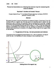
Figure 2: Aggregate bandwidth of 1, 2, and 3 links in the TNW implementation on AuroraScience.
developed a Linux driver and a basic communication library. For the efficient support of the Pput scheme, the driver marks the address space of the injection buffers (allocated at boot time by the NWP) as write-combining and maps them into the address space of the threads by standard mmap kernel functions. Thus, threads can directly access the injection buffers avoiding time overhead from frequent context switches between user- and kernelmode. For receiving data and notifications from the NWP, the driver allocates contiguous memory areas for each virtual channel. Control and status registers of the NWP are mapped on separate addresses and are accessible directly from user-space. The communication library implements a custom API and provides functions to send and receive messages, and to configure, control, and monitor the behavior of the NWP. The most relevant communication functions are tnwSend to send a message, tnwCredit to initiate a receive operation, as well as functions to test or wait (poll) for the completion of receive (and send) operations. The structure of many scientific codes is Single Program Multiple Data (SPMD). Typical communication patterns, like sending on all nodes data in direction x+ and receiving from x-, are readily translated to our API: tnwCredit to initiate receiving from x- and tnwSend to start transmission to x+, followed by tests for completion of the transfer and availability of the data.
4. Results and Conclusions The TNW is implemented as a highly pipelined design which runs on the Altera Stratix IV GX230 at a frequency of 250 MHz, using about 18% of the logic and 17% of the embedded memory. Taking into account protocol overhead, each TNW link has a maximal theoretical bandwidth of 0.91 GByte/s. Figure 2 shows the effective bandwidth of the TNW which scales well when data is simultaneously sent over 1, 2, and 3 links. This implementation uses the Pput scheme and the bandwidth does not exceed ≈ 0.5 GB/s per link when flushing of WC buffers is software controlled. On the other hand, when flushing of WC buffers is handled by the re-order logic in the NWP, the Pput scheme achieves a maximal transmission bandwidth of 0.83 GBbyte/s per link, i.e. 90% of the theoretical bandwidth, and has an average latency of 1.67 µsec (measured as transfer time of a message with 128 B payload). In a first test implementation of the Nget scheme, we find 6
Marcello Pivanti
An FPGA-based Torus Network
a maximal bandwidth of 0.76 GByte/s and an average latency of 2.16 µsec. The NWP-to-NPW latency, i.e. the time from the instant when a packet enters the NWP to the instant when it is ready to be delivered to the CPU, is about 0.6 µsec (of which 0.24 µsec arise from the PHYs). Since each PCIe transfer to or from the CPU memory causes about 0.2 µsec additional latency, we estimate a software overhead of ≈ 0.7 µsec for the Pput scheme, and ≈ 0.8 µsec for the Nget scheme. As an application test of the TNW and of the communication primitives we have adapted a 2D fluid-dynamics simulation code based on the Lattice-Boltzmann method. This code has also been used on QPACE [8], and we have optimized it for AuroraScience. On a 16-node system we obtain about 36–39 % of the peak performance of 160 Gflops double-precision per node. In this paper we have presented the design of a torus network which provides efficient nearestneighbor communications and allows fine grained parallel programming. The TNW design has been successfully integrated into the QPACE and AuroraScience machines, and we plan to make it available as open source project [9]. An optimized implementation of the Nget scheme is under development [10]. Future work may explore improved link technologies or functional extensions, like support for more general communication patterns. Acknowledgements: We like to thank the members of the QPACE project, in particular T. Mauer, A. Nobile, D. Pleiter, and T. Streuer for important contributions to the design of the TNW and for their strenuous efforts to integrate and test it in QPACE. We thank K.H. Sulanke for the design of the test-boards on which most of the TNW logic has been developed. We are grateful to R. Tripiccione for many discussions and advices from the APE experience. We thank AuroraScience for stimulating our work. M.P. has been supported by DFG (SFB/TR55) and H.S. by University Milano Bicocca.
References [1] F. Belletti, et al. (APE), Computing for LQCD: apeNEXT, Computing in Science and Engineering 8 (2006) 18. [2] P. A. Boyle et al., Overview of the QCDSP and QCDOC computers, IBM Journal of Research & Development 49 (2005) 351. [3] M. Lüscher, Lattice QCD on PCs? Nucl. Phys. (Proc. Suppl.) 106 (2002) 21. [4] G. Bilardi, et al., The Potential of On-Chip Multiprocessing for QCD Machines, HiPC 2005, LNCS vol. 3769, Springer (2005). [5] G. Goldrian, et al., QPACE: Quantum Chromodynamics Parallel Computing on the Cell Broadband Engine, Computing in Science and Engineering, 10 n. 6 (2008) 46. [6] H. Baier, et al., QPACE: power-efficient parallel architecture based on IBM PowerXCell 8i, Computer Science - Research and Development, 25 (2010) 1865. [7] L. Scorzato, AuroraScience, PoS(Lattice 2010) 039. [8] L. Biferale, et al., Lattice Boltzmann fluid-dynamics on the QPACE supercomputer, ICCS Proc. 2010, Procedia Computer Science, 1 (2010) 1069. [9] http://sourceforge.net/projects/ftnw [10] F. Mantovani, et al., in preparation
7