262
JOURNAL OF MULTIMEDIA, VOL. 7, NO. 3, JUNE 2012
An Improved Method of Detecting Edge Direction for Spatial Error Concealment Yan Zhao, Hexin Chen, Shigang Wang School of Communication Engineering, Jilin University, Changchun, China Email: {zhao_y,
[email protected]};
[email protected]
Moncef Gabbouj Institute of Signal Processing, Tampere University of Technology, Tampere, Finland Email:
[email protected]
Abstract—Sobel operator is widely used to detect the edge direction in most spatial error concealment methods. However, Sobel operator may not work when detecting edge directions in the case of existing line in the image. This paper designs an advanced method of detecting edge directions, which can estimate the direction of both step edge and line correctly. The benefit of the advanced edge detection method is that all edge directions including step edges and lines can be detected properly. The proposed method is applied in a spatial error concealment method. Experimental results show that the advanced method yields better objective and subjective quality than that of using Sobel operator for determining edge direction only. Index Terms—edge direction, Sobel, line, error concealment
I. INTRODUCTION Spatial error concealment uses correlation between adjacent pixels in an image to recover the lost pixels. There have been many studies on spatial error concealment methods. The edge feature in neighboring blocks of the corrupted block is often required to estimate in the spatial domain in order to recover edge information inside the corrupted blocks. The Sobel operator is widely used to detect the edge direction in many spatial error concealment methods. A content-adaptive error concealment algorithm was proposed in [1], which calculated local edge gradient magnitude and angular direction by Sobel operator and concealed the edge block by directional interpolation. The local edge gradient magnitude and angular direction at the pixel were calculated by convolving pixel values with the 3×3 Sobel operators in [2] to implement the hybrid error concealment based on block content. A spatial error concealment algorithm using directional extrapolation used Sobel masks to determine the direction of edge traversing the to-be-recovered pixel, which was recovered by corresponding directional extrapolation [3]. The algorithms in [4] and [5] applied a horizontal and vertical Sobel mask on the luminance value of each pixel at the missing area boundaries to detect the edges of the missing Corresponding author: Yan Zhao;
© 2012 ACADEMY PUBLISHER doi:10.4304/jmm.7.3.262-268
block, which was further concealed by directional interpolation and main direction smoothing. The Sobel operator with constant 1/4 was adopted in [6] to calculate the amplitude and angle of the edge gradient to restore edge components of the lost macroblocks for I frame concealment. Fine directional interpolation for spatial error concealment was proposed in [7], which used Sobel masks to roughly detect edge orientations for further refinement step. The algorithm of concealment of damaged block using projection onto convex sets in [8] used 3×3 Sobel mask operators as edge orientation detector to determine if a missing bock is with a particular orientation for further directional filtering. The early work in [9] selected Sobel operator for gradient estimation for multidirectional interpolation for spatial error concealment. The algorithm in [10] used also 3×3 Sobel operators to determine the potential edge direction of the 4×4 block, which is concealed by Intra_4×4 prediction in H.264/AVC corresponding to the potential edge direction. Edges play an important role in the subjective image quality because the human visual system is sensitive to the structural information revealed by edges. Therefore, restoring edge features of the lost macroblocks becomes a necessary job for spatial error concealment. The accuracy of edge detection determines the correct estimation of the edge features and determines further the performance of spatial error concealment algorithm. However, using the Sobel operator to detect edge direction does not always work. It may give wrong edge direction if the edge is a line since it is a first-order operator. Therefore, the detection of edges and their directions is not accurate for corrupted blocks with lines. In this paper, a new method is designed to find out wrong directional estimation detected using Sobel operator and an advanced method is also proposed to estimate the direction of lines correctly. Thus, the edge direction accuracy can be improved significantly. The proposed method is applied in a spatial error concealment algorithm to conceal the corrupted blocks. The paper is organized as follows. Section 2 and 3 describe the proposed method of detecting edge direction and concealment. In Section 4, experimental results are given. Conclusions are drawn in Section 5.
JOURNAL OF MULTIMEDIA, VOL. 7, NO. 3, JUNE 2012
263
TABLE I. RELATIONSHIP BETWEEN THE RANGES OF DIRECTIONS.
Figure 1. Eight edge directions.
II. METHOD OF DETECTING EDGE DIRECTION In general, there are two types of edges in an image: step edge and line. It is worth noting that the line is with only one pixel width here. The angle of the edge direction in most error concealment is rounded to the nearest 22.5°, which means that there are 8 different directions between 0° and 180° as shown in Fig.1 The operational flow of estimating the edge direction is sketched in Fig. 2. We firstly detect the edge direction by using traditional Sobel operator. Then we check if the direction is correct by using our proposed detection method. If the direction detected by Sobel operator is correct, the direction is output as the step edge direction, otherwise, we may check if it is a line and if so we will determine the direction of the line by using our proposed method. Otherwise, we may determine there is not edge in the image. A. Detecting Edge Direction of Step Edge Sobel operator is an effective tool which is widely used for determining direction of the step edge. In our proposed method, the 3×3 Sobel operator is used for detecting edge direction firstly. In order to estimate the edge direction existed in a subimage or a mask with size 3×3 as shown in Fig.3, the simplified calculation below is developed.
tan θ AND EIGHT
Range of tan θ
Direction
- 1/4 ≤ tan θ < 1/4 1/4 ≤ tan θ < 3/4 3/4 ≤ tan θ < 3/2 3/2 ≤ tan θ < 9/2 tan θ ≥ 9/2 or tan θ < -9/2
D0 D1 D2 D3 D4
-9/2 ≤ tan θ < -3/2 -3/2 ≤ tan θ < -3/4 -3/4 ≤ tan θ < -1/4
tan θ =
D5 D6 D7
Gy
(1)
Gx
where θ is the angle of the edge direction. G y = ( x 2 + 2 x5 + x8 ) − ( x 0 + 2 x3 + x 6 ) G x = ( x 6 + 2 x 7 + x 8 ) − ( x 0 + 2 x1 + x 2 )
(2)
The relationship between ranges of tan θ and eight directions is illustrated in Table 1. Sobel operator is effective for estimating the correct direction of the step edge. However, it might provide wrong result if the edge is a line, e.g., if the mask is like that shown in Fig.4. Obviously, this mask is in a line direction of 0°, but, the result given by Sobel operator is 45°. Therefore, it is necessary to find out the case when Sobel operator cannot work properly and design a method to detect line direction correctly. After the edge direction is detected by Sobel operator, the correction of the direction can be checked by:
Δx = xi +1 − xi + xi − xi −1
(3)
where xi is the center of the mask, that is x4 in Fig.3, xi +1 and xi −1 are two adjacent pixel values of xi along the detected direction which are given by:
Figure. 3 The 3×3 subimage or mask.
Figure 2. Flow chart of estimating edge direction
© 2012 ACADEMY PUBLISHER
100
100
99
10
11
10
100
99
100
Figure. 4 An example of 3×3 mask
264
JOURNAL OF MULTIMEDIA, VOL. 7, NO. 3, JUNE 2012
⎧⎧xi +1 = x5 if the direction is D0; ⎪⎨ ⎪⎩xi −1 = x3 ⎪⎧x = ( x + x + 0.5) / 2 2 5 ⎪⎨ i +1 if the direction is D1; ⎪⎩xi −1 = ( x3 + x6 + 0.5)/2 ⎪ ⎪⎧xi +1 = x2 if the direction is D2; ⎪⎨x = x ⎪⎩ i −1 6 ⎪⎧xi +1 = ( x1 + x2 + 0.5) / 2 if the direction is D3; ⎪⎨ ⎪⎩xi −1 = ( x6 + x7 + 0.5) / 2 ⎨ ⎪⎧xi +1 = x1 if the direction is D4; ⎪⎨x = x ⎪⎩ i −1 7 ⎪⎧xi +1 = ( x0 + x1 + 0.5) / 2 if the direction is D5; ⎪⎨ ⎪⎩xi −1 = ( x7 + x8 + 0.5) / 2 ⎪⎧x = x ⎪⎨ i +1 0 if the direction is D6; ⎪⎩xi −1 = x8 ⎪ (4) ⎪⎧xi +1 = ( x0 + x3 + 0.5) / 2 ⎪⎨x = ( x + x + 0.5) / 2 if the direction is D7. 5 8 ⎩⎪⎩ i −1
where x0 , x1 , … x8 are the pixel values in the mask shown in Fig.3. Then, the maximum line magnitude and its direction are obtained by: magl = max(mDi ), i = 0,1,..., 7 (7)
Dm = arg max(mDi ) , i = 0,1,..., 7
(8)
Di
If the maximum line magnitude magl is larger than a certain threshold β , a line in the mask and the line direction Dm are considered. Otherwise, the line magnitude of the direction is set zero, i.e.,, magl =0 for direction Dm . III. CONCEALMENT BY PIXEL EXTRPOLATION The pixels in the missing block are recovered pixel-bypixel in our algorithm. Assume the pixel to be recovered is y, then eight edge directions which have chance to traverse y are shown in Fig.5. We use eight masks with the size of 3×3, each for one direction, to determine if there is an edge that can be covered by one of the eight directions traversing y. Pixels in the mask are denoted by x0 to x8 as shown in Fig.3.
where x0 , x1 , … x8 are the pixel values in the mask as
The nearest pixel to y along any direction is denoted y1 and the second nearest pixel is denoted y2 .
shown in Fig.3. If Δx is larger than a certain threshold α , it means the direction detected by Sobel operator is not correct and the line edge direction will be detected further. Otherwise, the direction of the edge is considered correctly and the magnitude of the edge can be calculated by:
pixel x4 in the 3×3 mask for these directions is y2 . The
mag s = G + G
(5)
3×3 masks for directions D3 and D5 are centered at y1 ,
B. Detecting Edge Direction of Line If the direction detected by Sobel operator is not correct, the line and its direction in the 3×3 mask should be further detected. In order to detect line direction, firstly the eight line magnitude values corresponding to eight directions should be calculated by:
that is, the pixel x4 in the 3×3 mask for directions D3
2 x
2 y
⎧mD0 = 2(x3 + x4 + x5 ) − x0 − x1 − x2 − x6 − x7 − x8 ⎪m = 2((x + x + 0.5)/ 2 + x + (x + x + 0.5)/ 2) − x − x 3 6 4 2 5 2 3 ⎪ D1 ⎪ − x5 − x6 − (x1 + x4 + 0.5)/ 2 − (x4 + x7 + 0.5)/ 2 ⎪ ⎪mD2 = 2(x2 + x4 + x6 ) − x0 − x1 − x3 − x5 − x7 − x8 ⎪m = 2((x + x + 0.5)/ 2 + x + (x + x + 0.5)/ 2) − x − x 6 7 4 1 2 1 2 ⎪ D3 x x ( x x 0.5)/ 2 ( x x 0.5)/ 2 − − − + + − + + ⎪ 6 7 3 4 4 5 ⎨ m 2( x x x ) x x x x x = + + − − − − − 1 4 7 0 3 6 2 5 − x8 ⎪ D4 ⎪mD5 = 2((x0 + x1 + 0.5)/ 2 + x4 + (x7 + x8 + 0.5)/ 2) − x0 − x1 ⎪ − x7 − x8 − (x3 + x4 + 0.5)/ 2 − (x4 + x5 + 0.5)/ 2 ⎪ ⎪m = 2(x + x + x ) − x − x − x − x − x − x 0 4 8 1 2 5 3 6 7 ⎪ D6 ⎪mD7 = 2((x0 + x3 + 0.5)/ 2 + x4 + (x5 + x7 + 0.5)/ 2) − x0 − x3 ⎪ − x5 − x8 − (x1 + x4 + 0.5)/ 2 − (x4 + x7 + 0.5)/ 2 ⎪⎩
(6)
Example positions of y1 and y2 on directions D2 and D7 are shown in Fig.6. The 3×3 masks for directions D0, D1, D2, D4, D6 and D7 are centered at y2 , that is, the
and D5 is y1 . For each direction from D0 to D7, we detect the edge direction and its magnitude ( mag s or
Figure. 5 Eight edge directions which have chance to traverse the to-be-recovered pixel.
Figure. 6 Example positions of
y1 D7.
© 2012 ACADEMY PUBLISHER
and
y2
along directions D2 and
JOURNAL OF MULTIMEDIA, VOL. 7, NO. 3, JUNE 2012
265
magl ) in its corresponding 3×3 mask by using the above edge detection method. The direction with the maximum magnitude ( mag s or magl ) is considered as the edge direction which traverses the pixel to be recovered. If the magnitudes of eight directions are all zero, it indicates that there is not any edge traversing the pixel to be recovered. In other words, the pixel y is supposed to be in a flat region. If there is an edge direction traversing the pixel y, it will be concealed through extrapolation of two pixels y1 and y2 along the determined direction as:
y=
2 1 y1 + y 2 3 3
(9)
If pixel y is in a flat region, it will be recovered based on weighted pixel averaging [11]. The order of pixels to be recovered in the missing block is from the outer layer to the inner layer [3]. IV. EXPERIMENTAL RESULTS In order to evaluate the performance of the proposed method of detecting edge direction, the simple Sobel operator detection in [3] is replaced by our proposed method. It is worth clarifying that eight directions as shown in Table 1 are used in our experiment instead of ten directions in [3]. The 512×512 Lena image and the 512×384 StockCurve image are used to evaluate the performance of the proposed algorithm. The StockCurve image is the typical image appeared in the stock market, which is full of lines. Both cases of 8×8 block and 16×16 block are considered in our experiments because the case of 8×8 block was used in most previous spatial error concealment methods and the case of 16×16 block was considered in some of previous studies on error concealment. In the experiment, α = 10 and β = 200 for both cases of 8×8 block and 16×16 block. The traditional PSNR is measured to evaluate the quality of recovered image. PSNR is defined by: PSNR = 10log
2552 M −1 N −1
1 2 [ f ( x, y) − F ( x, y)] ∑∑ MN x =0 y =0
(dB)
(10)
where M is the width of the image, N is the height of the image, f ( x, y ) and F ( x, y ) are the pixel values of the original image and the reconstructed image respectively. Firstly the case of 8×8 block with loss rate 25% is tested. Table 2 lists the PSNR comparison results between our proposed method and the previous work in TABLE II. PERFORMANCE COMPARISON FOR 8×8 BLOCK Image Lena StockCurve
Previous [3] (dB) 33.22 23.81
© 2012 ACADEMY PUBLISHER
Proposed (dB) 33.45 25.25
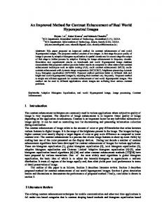
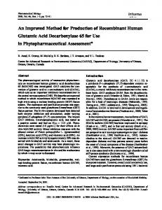
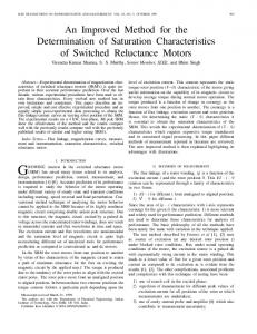
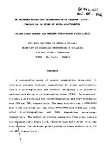
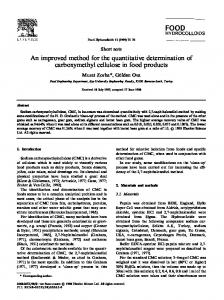
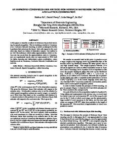
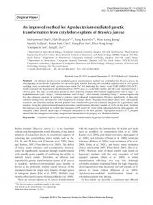
[3]. The difference between these two methods is that the advanced method of detecting edge direction in the error concealment is used in our proposed method, while the Sobel operator is only used for detecting edge directions in [3]. Table 2 shows that the PSNR performance for Lena image has 0.23dB gain with our proposed method comparing with that of the previous method. While for StockCurve image, which has more lines in the image, the PSNR performance has about 1.44 dB gain against the previous method. Fig.7 illustrates the comparison and difference of the corresponding reconstructed Lena images recovered by the previous work [3] and the proposed method: (a) is the original image, (b) is the corrupted image, (c) is the reconstructed image using algorithm in [3] and (d) is the reconstructed image given by the proposed technique. Fig.8 shows the comparison of the corresponding reconstructed StockCurve images recovered by the previous work [3] and the proposed method: (a) is the original image, (b) is the corrupted image, (c) is the reconstructed image using algorithm in [3] and (d) is the reconstructed image given by the proposed method. Based on the comparison shown in Fig.7 and Fig.8, it is obviously that the proposed algorithm can recover the corrupted block with better subjective quality, especially for images with more lines. For better subjective evaluation, the enlarged portions of the StockCurve image are shown in Fig.9. By comparing (c) and (d), it is clearly shown that the line is recovered much better by using the proposed method. The second experiment was carried out with the case of 16×16 block with loss rate 10%. Table 3 lists the PSNR comparison results between our proposed method and the previous work in [3]. The results in Table 3 demonstrate that both Lena image and StockCurve image have better objective quality comparing with the previous method. The concealed results of Lena image are shown in Fig.10. They are: (a) the damaged image, (b) the concealed image using algorithm in [3] and (c) the concealed image given by the proposed technique. Fig.11 shows the concealed results of StockCurve image: (a) is the damaged image, (b) is the concealed image using algorithm in [3] and (c) is the concealed image given by the proposed technique. It can be seen that the concealed image by using the proposed method looks much better. V. CONCLUSIONS In this paper, an advanced edge detection method, which can estimate both step edge and line direction correctly, is proposed. The proposed method of detecting edge direction is applied in a spatial error concealment algorithm in order to evaluate its performance. Experimental results show that the proposed edge direction detection method can provide more accurate edge direction for further spatial error concealment. Therefore, both objective and subjective of the recovered images can be improved significantly, especially for images with more lines.
266
JOURNAL OF MULTIMEDIA, VOL. 7, NO. 3, JUNE 2012
(a) Original StockCurve image (a) Original Lena image
(b) Corrupted image
(b) Corrupted image
(c) Reconstructed image by [3], PSNR = 23.81dB.
(c) Reconstructed image by [3], PSNR = 33.22dB
(d) Reconstructed image by proposed method, PSNR = 25.25dB Figure. 8 Comparison results of StockCurve image for the case of 8×8 block
ACKNOWLEDGMENT
(d) Reconstructed image by proposed method, PSNR = 33.45dB. Figure. 7 Comparison results of Lena image for the case of 8×8 block
© 2012 ACADEMY PUBLISHER
This work was supported by the project of National Natural Science Foundation of China under Grant 60832002, 61171078 and in part by the Research Fund for Doctorial Program of Higher Education of China under Grant 20110061110084 and the Outstanding Youth Foundation of Jilin University under Grant 200905018.
JOURNAL OF MULTIMEDIA, VOL. 7, NO. 3, JUNE 2012
267
(a)
(a) Corrupted image
(b)
(b) Concealed image by [3], PSNR = 35.91dB
(c)
(d) Figure. 9 Comparison of the zoomed portions in Fig.8.
(c) Concealed image by proposed method, PSNR = 36.00dB Figure. 10 Comparison results of Lena image for the case of 16×16 block
TABLE III. PERFORMANCE COMPARISON FOR 16×16 BLOCK Image
Previous [3] (dB)
Proposed (dB)
Lena
35.91
36.00
StockCurve
29.34
29.41
REFERENCES [1] R. Zhang, Y. Zhou. and X. Huang, “Content-adaptive spatial error concealment for video communication”, IEEE Trans. Consumer Electronics, vol.50, no.1, pp. 335-341, 2004.
© 2012 ACADEMY PUBLISHER
[2] M.-H. Jo, H.-N. Kim and W.-J. Song, “Hybrid error concealments based on block content”, IET Image Processing, vol.1, no.2, pp.141-148, 2007. [3] Y. Zhao, H. Chen, X. Chi, J. S. Jin, “Spatial Error Concealment Using Directional Extrapolation”, Proceedings of Digital Image Computing: Techniques and Applications, pp. 278-283, 2005. [4] O. Nemethova, A. Al Moghrabi, M. Rupp, “An Adaptive Error Concealment Mechanism for H.264/AVC Encoded Low-Resolution Video Streaming”, Proceedings of 14th European Signal Processing Conference (EUSIPCO), pp. 1-5, 2006. [5] O. Nemethova, A. Al Moghrabi, M. Rupp, “Flexible Error Concealment for H.264 Based on Directional Interpolation”, Proceedings of the 2005 International
268
JOURNAL OF MULTIMEDIA, VOL. 7, NO. 3, JUNE 2012
(a) Corrupted image
(b) Concealed image by [3], PSNR = 29.34dB
(c) Concealed image by proposed method, PSNR = 29.41dB. Figure. 11 Comparison results of StockCurve image for the case of 16×16 block
[6]
[7]
[8]
[9]
[10]
[11]
Conference on Wireless Networks Communications and Mobile Computing”, vol.2, pp. 1255-1260, 2005. Wei-Ying Kung, Chang-Su Kim and C.-C. Jay Kuo, “Spatial and Temporal Error Concealment Techniques for Video Transmission Over Noisy Channels”, IEEE Trans. on Circuits and System for Video Technology, vol.16, no.7, pp.789–802, 2006. Wonki Kim, Jasung Koo and Jechang Jeong, “Fine Directional Interpolation for Spatial Error Concealment”, IEEE Transactions on Consumer Electronics , vol.52, no.3, pp.1050-1056, 2006. H. Sun and W. Kwok, “Concealment of damaged block transform coded images using projections onto convex sets”, IEEE Trans. Image Processing, vol.4, pp.470-477, 1995. Wilson Kwok and Huifang Sun, “Multi-directional interpolation for spatial error concealment”, IEEE Trans. Consumer Electronics, vol.39, pp. 455-460, 1993. Y. Zhao, D. Tian, M.M.Hannukasela, M. Gabbouj, Spatial Error concealment Based on Directional Decision and Intra Prediction, IEEE International Symposium on Circuits and Systems, Volume 3, pp.2899-2902, 2005. Ye-Kui Wang, M. M. Hannuksela, Viktor Varsa, Ari Hourunranta and Moncef Gabbouj. The error concealment feature in the H.26L test model. Proc. of ICIP 2002, vol.II, pp.729-732, 2002.
© 2012 ACADEMY PUBLISHER
Yan Zhao was born in Jilin, China, in 1971. She received the B.S. degree in communication engineering in 1993 from Chan-g-chun Institute of Posts and Telecommunications, the M.S. de-gree in communication and electronic in 1999 from Jilin Univ-ersity of Technology, and the Ph.D. degree in communication and information system in 2003 from Jilin University. She has been a postdoc researcher in the Digital Media Institute of Tampere University of Technology in Finland from Mar.2003 to Dec.2003. From Mar. 2008 to Aug.2008, she was a visiting p-rofessor in the Institute of Communications and Radio-Frequency Engineering in the Vi-enna University of Technology. She currently is an associate professor of communication enginee-ring. Her research interests include image and video coding, multimedia signal processing and error concealment for audio and video transmitted over unreliable networks. Dr. Zhao is a member of IEEE. Hexin Chen was born in Jilin, China, in 1949. He received the M.S. and Ph.D. degrees in communication and electronic in 1982 and 1990 from Jilin University of Technology, respectively. He has been a visiting scholar in the University of Alberta from 1987 to 1988. From Feb.1993 to Aug.1993, he was a visiting professor in Tampere University of Technology in Finlan-d. He currently is a professor of communication engineering. His research interests include image and video coding, multidimensional signal processing, image and video retrieval and audio and video synchronization. Shigang Wang was born in Jilin, China, in 1962. He received the B.S. degree in 1983 from Northeastern University, the M.S degree in communication and electronic in 1998 from Jilin University of Technology, and the Ph.D. degree in communication and information system in 2001 from Jilin University. He currently is a professor of communication engineering. His research interests include image and video coding, multidimensional signal processing and stereoscopic and multi-view video coding. Moncef Gabbouj received his BS degree in electrical engineering in 1985 from Oklahoma State University, Stillwater, and his MS and PhD degrees in electrical engineering from Purdue University, West Lafayette, Indiana, in 1986 and 1989, respectively. Dr. Gabbouj is currently an Academy Professor and Professor at the Department of Signal Processing at Tampere University of Technology, Tampere, Finland. His research interests include multimedia content-based analysis, indexing and retrieval; nonlinear signal and image processing and analysis; and video processing, coding and communications.