An Improved Physical Layer Network Coding. Scheme for Two-Way Relay Systems. Yidong Lang, Dirk Wübben and Karl-Dirk Kammeyer. Department of ...
2010 International ITG Workshop on Smart Antennas (WSA 2010)
An Improved Physical Layer Network Coding Scheme for Two-Way Relay Systems Yidong Lang, Dirk W¨ubben and Karl-Dirk Kammeyer Department of Communications Engineering, University of Bremen Otto-Hahn-Allee NW1, D-28359 Bremen, Germany Email: {lang, wuebben, kammeyer}@ant.uni-bremen.de Abstract—In this paper we consider a two-way relaying system with two sources A, B and one relay R, where the two sources desire to exchange information through the relay. The transmission consists of two states: multiple access (MAC) stage, where A and B transmit the channel-coded signals to R simultaneously, and broadcast (BC) stage, where R transmits towards both A and B. One critical process at R is to decode the superimposed signal from A and B in such a way that A and B could decode the information from each other reliably at the BC stage. Instead of decoding the individual information belonging to A and B separately, R aims to decode the superimposed signal to the network-coded combination of the two source information, i.e., the binary XOR of the two source information. We refer this decoding process as the joint channel decoding and physical network encoding (JCNC). In this paper, a novel iterative decoding algorithm is presented for the physical network coding scheme, which is applicable to any linear channel code, e.g. Low-Density Parity-Check (LDPC) code. Furthermore, the two-way relaying scheme is extended to distributed multiple input multiple output (MIMO) multi-hop networks. Based on an antenna selection criterion within each virtual antenna array (VAA), the end-to-end (e2e) BER of the multi-hop system can be further reduced. Simulation results show that the proposed scheme outperforms other recently proposed network coding schemes with slightly increased complexity. Index Terms—Physical network coding, relay, iterative decoding, distributed MIMO, antenna selection, sum product algorithm.
I. I NTRODUCTION
AND
S YSTEM M ODEL
Network coding has been shown to improve the network throughput significantly, which was first proposed in [1]. The network coding scheme was originally considered as a network-layer technique for wired networks. In wireless network, the broadcast nature of the wireless physical medium is usually considered to cause enormous interference if several nodes transmit simultaneously. On the contrary, physical network coding (PNC) can employ this broadcast nature as a capacity-boosting approach for two-way or multi-way communication network, [2], [3], [4], [5]. Especially, a direct application of physical network coding arises for the two-way (or bi-directional) point-to-point communication. A simple two-way relay system with two sources A and B, and one relay R is depicted in Fig. 1. Source A and source B wish to exchange information between each other through the relay R. We denote bA ∈ {0, 1}K and bB ∈ {0, 1}K as the This work was supported in part by the Central Research Funding, University of Bremen under grant 01/129/07.
978-1-4244-6072-4/10/$26.00 ©2010 IEEE
Stage I: MAC yR = xA + xB + nR R xA
xB
A
B
Stage II: BC xR R yA = xR + nA A
yB = xR + nB B
Fig. 1. Two source A and B wish to exchange information through the relay R, which consists of two stages: multiple access (MAC) stage, where A and B transmit the signals xA and xB to R simultaneously, and broadcast (BC) stage, where R transmits xR towards both A and B.
information vector of source A and source B. The information is encoded by the same linear code with a code rate of Rc = K N into the codeword vectors cA ∈ {0, 1}N and cB ∈ {0, 1}N at the sources A and B, respectively. The encoded vectors are BPSK-modulated to xA ∈ {−1, 1}N and xB ∈ {−1, 1}N according to the mapping rule 0 → 1 and 1 → −1. The communication consists of two stages: multiple access (MAC) and broadcast (BC). In the MAC stage, the two source A and B transmit their information xA and xB to the relay simultaneously over an AWGN channel. Under the assumption of perfect synchronization, the received signal at the relay R is yR = xA + xB + nR ,
(1)
where the elements of nR are identically distributed (i.i.d) zero-mean Gaussian random variables with variance σn2 . We assume that both sources A and B have the same power constraint E{||xA ||2 } ≤ P and E{||xB ||2 } ≤ P . According to the physical network coding scheme introduced in [2], the XOR of the source information denoted by bA⊕B = bA ⊕bB ∈ {0, 1}K can be estimated at the relay from the received signal yR , i.e., ˆ A⊕B ∈ {0, 1}K . Then, bR is encoded by the same bR = b channel code, and the code vector cR BPSK-modulated to xR . In the BC stage, the relay R broadcasts xR to both A and B. It is assumed that the relay R has the same power constraint
107
as A and B, i.e., E{||xR ||2 } ≤ P and the noise variance at A and B is σn2 . Thus, the received signals at A and B are given by (2a) yA = xR + nA , yB = xR + nB .
(2b)
with 3 rows and 6 columns ⎡ 1 1 H = ⎣0 1 1 1
1 1 1 0 0 0
⎤ 0 0 1 0⎦ , 0 1
(3)
ˆ R , which contains the inAt both A and B, the information b formation of bA⊕B , is estimated from yA and yB , respectively. Since A and B know what has been transmitted at the MAC stage, A and B can obtain the information from each other ˆ R ⊕ bA and ˆB = b simply by means of the binary XOR, i.e., b ˆ R ⊕ bB . ˆA = b b A critical process at the relay R is to decode the superimposed signal from A and B in such a way that A and B could decode the information from each other reliably at the BC stage. In this paper, we will focus on deriving a decoding algorithm for yR → bR . In [3], [6], joint channel decoding and network encoding algorithms have been derived for Repeat Accumulate (RA) codes and turbo codes, respectively. The idea of these algorithms is that under the assumption of the same linear code applied at both source nodes, the XOR of the encoded vectors cA⊕B = cA ⊕ cB ∈ {0, 1}N is also a valid codeword of the ˆ A⊕B directly channel code. Hence, the relay can decode yR to b without changing the decoder structure. Different from the above mentioned approach, we will estimate the sum of the two source information denoted by bA+B = bA + bB ∈ {0, 1, 2}K from the received signal yR first. In this step, we can consider a virtual encoder with bA+B as its input and cA+B = cA + cB ∈ {0, 1, 2}N as its output. Based on this virtual encoder, we develop a corresponding ˆ A+B at the decoding algorithm to estimate the information b ˆ ˆ relay. In the next step, we map bA+B to bA⊕B . The idea is inspired by the fact that cA+B contains more useful information than cA⊕B related to the decoding of bA⊕B . To accomplish this challenge, we introduce an improved physical network coding scheme for arbitrary linear code in this paper. To this end, a virtual encoder with respect to the two-way multiple access transmissions is constructed and a corresponding iterative decoding algorithm is developed based on the Sum-Product Algorithm (SPA) [7]. Furthermore, the extension to distributed MIMO multi-hop systems with antenna selection is considered under the concept of virtual antenna arrays (VAA) [8]. The remainder of this paper is organized as follows. Section II presents a common joint channel and physical network coding scheme [3]. A generalized joint channel decoding and network encoding approach is introduced in Section III. In combination with antenna selection, the decoding approach is applied to distributed MIMO multi-hop network in Section IV. Finally, in Section V and VI simulation results are presented and conclusion is given.
and the corresponding generator matrix G ∈ {0, 1}3×6 equals ⎡ ⎤ 1 0 0 1 0 1 G = ⎣0 1 0 1 1 1⎦ . (4) 0 0 1 1 1 0
II. A S IMPLE J OINT C HANNEL AND P HYSICAL N ETWORK C ODING (S-JCNC) S CHEME In order to discuss the physical network coding scheme more clearly, we consider a 1/2-rate LDPC code as an example. It is defined by the parity-check matrix H ∈ {0, 1}3×6
Note that since cA and cB are codewords belonging to the same linear code, also the module-2 sum cA⊕B is also a valid code word. Let n index the bit of a codeword. Tab. I summarizes the relationship between cA (n), cB (n), cA⊕B (n), cA+B (n), xA (n), xB (n) and xA+B (n). According
The code words cA and cB are obtained as follows, cA = bA ⊗ G ,
cB = bB ⊗ G .
(5)
The encoding process is illustrated in Fig. 2 [7]. b0
b1
b2
c0
c1
c2
c3
c4
c5
Fig. 2. LDPC encoder based on the generator matrix G in (4), where ⊕ denotes the operation module-2 sum.
The factor graph of the parity check matrix H in (3) is illustrated in Fig. 3, where ci decode the variable nodes and ⊕ denote constraint function within the check nodes. By using the SPA, the information which is encoded by this linear code can be decoded iteratively.
c0
c1
c2
c3
c4
c5
Fig. 3. Factor graph of the parity check matrix H in (3). ⊕ denotes the constraint function (module-2 sum) within the check nodes while cn denotes the variable nodes.
108
cA (n) 0 0 1 1
cB (n) 0 1 0 1
cA⊕B (n) 0 1 1 0
cA+B (n) 0 1 1 2
xA (n) 1 1 −1 −1
xB (n) 1 −1 1 −1
xA+B (n) 2 0 0 −2
TABLE I Mapping rules between encoded vectors and transmit vectors.
to Tab. I, the a-priori probabilities of {cA+B (n) = 0, 1, 2} and {xA+B (n) = 2, 0, −2} are Pr{cA+B (n) = 0} = Pr{xA+B (n) = 2} = 1/4 ,
(6a)
Pr{cA+B (n) = 1} = Pr{xA+B (n) = 0} = 1/2 , Pr{cA+B (n) = 2} = Pr{xA+B (n) = −2} = 1/4 .
(6b) (6c)
If cA⊕B (n) = 0 holds, cA+B (n) = 0 or 2 and xA+B (n) = 2 or −2 should also be satisfied. Hence, the probability of {cA⊕B (n) = 0} is the sum probability of {cA+B (n) = 0} and {cA+B (n) = 2} under the condition of the received signal yR (n), which is given by Pr{cA⊕B (n) = 0|yR (n)} = Pr{cA+B (n) = 0|yR (n)} + Pr{cA+B (n) = 2|yR (n)} ,
Pr{cA+B (n) = 2|yR (n)} Pr{cA+B (n) = 2}Pr{yR (n)|cA+B (n) = 2} = Pr{yR (n)} � � 1 (yR (n) + 2)2 = √ exp − . 2σn2 4 2πσn Pr{yR (n)}
Our new decoding approach, called generalized joint channel and network coding (G-JCNC), uses three probabilities [ Pr{cA+B (n) = 0|yR (n)} , Pr{cA+B (n) = 1|yR (n)} ,
(10)
Pr{cA+B (n) = 2|yR (n)} ] instead of [Pr{cA⊕B (n) = 0|yR (n)} , Pr{cA⊕B (n) = 1|yR (n)} ]
(8a)
(8b)
Similarly, the probability of {cA⊕B (n) = 1} under the condition of the received signal yR (n) is given by Pr{cA⊕B (n) = 1|yR (n)} Pr{cA+B (n) = 1}Pr{yR (n)|cA+B (n) = 1} = Pr{yR (n)} � � yR (n)2 1 exp − = √ . 2σn2 2 2πσn Pr{yR (n)}
III. G ENERALIZED J OINT C HANNEL AND P HYSICAL N ETWORK C ODING (G-JCNC)
(7)
with the a-posteriori probabilities Pr{cA+B (n) = 0|yR (n)} Pr{cA+B (n) = 0}Pr{yR (n)|cA+B (n) = 0} = Pr{yR (n)} � � (yR (n) − 2)2 1 √ exp − , = 2σn2 4 2πσn Pr{yR (n)}
network coding. The reason for this is, that the mapping from the received signal yR to the probability of cA⊕B discards useful information related to the decoding of bA⊕B . More specifically, cA+B (or xA+B ) contains more information than cA⊕B about bA⊕B .
(9)
Since the sum of the above three probabilities in (8) and (9) should be 1, the probability Pr{yR (n)} can be calculated. Once the probabilities are obtained, we can use the same linear decoder based on the parity check matrix H to decode the received signal yR at the relay. In this way, an estimation of the XOR of the two source information can be achieved, ˆ A⊕B . The implementation of S-JCNC is very i.e., bR = b simple without changing the decoder structure. However, it has been shown in [3] that there is a significant gap between its performance and the theoretical upper bound of physical
(11)
as the soft inputs of the decoder. In this way, we can fully exploit the useful information in yR which is provided by the channel coding. In the new approach, we decode the received ˆ A+B ∈ {0, 1, 2}K first and then signal yR at the relay to b ˆ A⊕B . As a result, the ˆ map the estimation bA+B to the XOR b decoder at the relay is different from the traditional linear decoder. We use the following steps to re-design the decoder: 1) Construction of a virtual encoder whose input is bA+B and output is cA+B ; 2) Construction of the factor graph based on the virtual encoder; 3) Design of the sum-product algorithm based on the factor graph. A. Virtual Encoder For G-JCNC, the task of the decoder at the relay can be viewed as estimating the superposition of the two inputs of the encoders at the two sources bA+B with respect to the received signal yR , i.e., yR → bA+B . In the absence of noise, the received signal yR is the linear superposition of the two transmit signals xA+B = xA + xB . Thus, the decoding process at the relay R can be regarded as the inverse of the superposition of the encoding process at A and B. To this end, we can view the decoder at the relay conceptually as the decoder of a virtual encoder with input bA+B and output cA+B . As shown in Fig. 4, the virtual encoder has the same structure as the LDPC encoder illustrated in Fig. 2 except that the XOR-operation is replaced by a function f � , where � denotes the degrees of the function, which is the number of the edges connected to the function in Fig. 4. Let j and k
109
b0
c0 Fig. 4.
b1
c1
b2
c2
f4
f4
f3
f3
c3
c4
c5
c0
index bits of bA+B and n index a bit of cA+B . For � = 3, the function f � with two inputs and one output needs to satisfy cA+B (n) = f 3 (bA+B (j), bA+B (k)) = cA (n) + cB (n) (12)
where cA (n) = bA (j) ⊕ bA (k) and cB (n) = bB (j) ⊕ bB (k) are according to the generator matrix G in (4) and the encoder in Fig. 2. Thus, we can obtain the expression of the function f � , if � = 3 with two inputs and one output as cA+B (n) = f 3 (bA+B (j), bA+B (k)) = bA (j) ⊕ bA (k)+bB (j) ⊕ bB (k) ⎧ 0, if bA+B (j) = 2, bA+B (k) = 2 ⎪ ⎪ ⎪ ⎪ 1, if bA+B (j) = 2, bA+B (k) = 1 ⎪ ⎪ ⎪ ⎪ 2, if bA+B (j) = 2, bA+B (k) = 0 ⎪ ⎪ ⎪ ⎪ if bA+B (j) = 1, bA+B (k) = 2 ⎨ 1, = 0 or 2, if bA+B (j) = 1, bA+B (k) = 1 ⎪ ⎪ 1, if bA+B (j) = 1, bA+B (k) = 0 ⎪ ⎪ ⎪ ⎪ 2, if bA+B (j) = 0, bA+B (k) = 2 ⎪ ⎪ ⎪ ⎪ 1, if bA+B (j) = 0, bA+B (k) = 1 ⎪ ⎪ ⎩ 0, if bA+B (j) = 0, bA+B (k) = 0
c3
c4
c5
c4 should satisfy the constraint function f 4 , e.g., if c1 , c2 , c3 are the inputs and c4 is the output, c4 = f 4 (c1 , c2 , c3 ) should hold and vice versa. In the following section, the decoding algorithm is discussed in detail.
C. Messages Initialization For simplicity, we define the message passing throughout the factor graph as a three probabilities vector p = [p0 , p1 , p2 ], where pi , ∀i denotes the probability that the value is i. The initial message of each variable nodes from the received signal yR can be calculated by p = [p0 , p1 , p2 ] = [Pr{cA+B (n) = 0|yR (n)}, Pr{cA+B (n) = 1|yR (n)}, Pr{cA+B (n) = 2|yR (n)}] , (15)
(13)
Note that if bA+B (j) = 1, bA+B (k) = 1 hold, cA+B (n) is equal to 0 or 2 in a random way. For the cases � > 3, the function f � can be easily extended by means of function nesting, f � = f 3 (bA+B (j), f 3 (bA+B (j − 1), · · · )) .
� �
c2
f3
Fig. 5. Tanner graph of the virtual encoder, where cn are the variable nodes and f � are the constraint functions within the check nodes defined in (13).
Virtual encoder with function f � defined in (13).
= bA (j) ⊕ bA (k) + bB (j) ⊕ bB (k) ,
c1
f3
with probabilities Pr{cA+B (n) = i|yR (n)} defined in (8) and (9). Note that we use the same message updating rules at the check nodes and variable nodes as the generic updating rules defined in [7]. In order to better understand the algorithm, we define the update function at the variable nodes as VAR and at the check nodes as CHK. Similar to (14), we can also use function nesting to compute the messages from the variable nodes (or check nodes) with degree of greater than three by
(14)
VAR(p,p� ,. . .) = VAR(p, VAR(p� , VAR(. , .)) , CHK(p,p� ,. . .) = CHK(p, CHK(p� , CHK(. , .)) ,
�−1 terms
The virtual encoder is now fully defined by the function f � in (13) and the function nesting in (14). B. Factor Graph for the Virtual Encoder Based on the previous definitions, the factor graph of the virtual encoder can be illustrated as shown in Fig. 5, where ci are the variable nodes and f � are the constraint functions with the check nodes defined in (13). In a factor graph, a check node represents a constraint on a subset of the variable nodes while the variable nodes are usually code bits. The variable nodes which are connected to the same check node should satisfy a predefined equation. Obviously, for example, c1 , c2 , c3 and
(16a) (16b)
where p and p� are the input message vectors to variable nodes or check nodes. We focus on the case that the variable nodes and check nodes have the degree of three in the following investigation.
D. Messages Going Out of Variable Nodes Assuming two input messages p = [p0 , p1 , p2 ] and p� = p�1 , p�2 ] arrive at the variable node cn of degree three, the probability that the code bit cn is 0 can be calculated as
[p�0 ,
110
follows, Pr(p, p� |cn = 0)Pr(cn = 0) Pr(p, p� ) � Pr(p|p , cn = 0)Pr(p� |cn = 0)Pr(cn = 0) = Pr(p, p� ) Pr(p|cn = 0)Pr(p� |cn = 0)Pr(cn = 0) = Pr(p, p� ) Pr(cn = 0|p)Pr(cn = 0|p� )Pr(p)Pr(p� ) = Pr(cn = 0)Pr(p, p� ) � (17) = 4βp0 p0 ,
Pr(cn = 0|p, p� ) =
�
) where β = Pr(p)Pr(p Pr(p,p� ) is a normalization factor. Note that here the probability Pr(cn = 0) equals 1/4. In a similar way, the probabilities Pr(ci = 1|p, p� ) and Pr(ci = 2|p, p� ) can be achieved by using Pr(cn = 1) = 1/2 and Pr(cn = 2) = 1/4
Pr(ci = 1|p, p� ) = 2βp1 p�1 ,
(18)
Pr(ci = 2|p, p )
(19)
�
= 4βp2 p�2
.
The message going out of one check node is then finally given by 1 CHK(p, p� ) =[p0 p�0 + p2 p�2 + p1 p�1 , 2 p1 p�2 + p2 p�1 + p1 p�0 + p0 p�1 , 1 p0 p�2 + p2 p�0 + p1 p�1 ] . 2 F. Finalization
If a certain number of iterations is reached or a given criterion is satisfied, the SPA will generate a soft version of the encoded information ˆ cA+B . According to the virtual encoder as shown in Fig. (4), the first 3 columns of cˆA+B contain the ˆ A+B . Finally, the PNC mapping is as soft information for b follows � 1 if Pr(ˆ cA+B (n) = 1) > 0.5, ∀n ˆ cA⊕B (n) = . (25) 0 else G. Summary of the Decoding Algorithm We summarize the proposed coding algorithm briefly. 1) Messages initialization: the initial messages for the variable nodes are computed from the received signal yR based on (8) and (9). 2) Updating rules for output messages going out of a variable node: the messages are updated by (20) VAR(p, p� ) = β[4p0 p�0 , 2p1 p�1 , 4p2 p�2 ] if the variable has two input messages p = [p0 , p1 , p2 ] and p� = [p�0 , p�1 , p�2 ]. Otherwise, the function nesting (16a) can be used to calculate the messages if the variable nodes has degree of greater than three. 3) Updating rules for output messages going out of a check node: the messages out of a check nodes are computed by (24). Similar to the updating rule for variable nodes, (16b) can be used for the check node with degree greater than three. 4) Finalization: if some criteria is satisfied, the decoding process will be stopped. Otherwise, go back to step 2.
Since the sum of the above three probabilities should be 1, the normalization factor β can be calculated, i.e., β = (p0 p�0 + p1 p�1 /2 + p2 p�2 )/4. Therefore, the messages going out of a variable node with degree three is given by VAR(p, p� ) = β[4p0 p�0 , 2p1 p�1 , 4p2 p�2 ] .
(20)
As mentioned before, if the degree of the variable node is greater than three, we can use the function nesting (16a) to update the messages. E. Messages Going Out of Check Nodes Assuming two input messages from the variable nodes ci and cj are p = [p0 , p1 , p2 ] and p� = [p�0 , p�1 , p�2 ], based on the function f � defined in (13), the probability that the code symbol cn is 0 can be calculated by Pr(cn = 0|p, p� ) = Pr(ci = 0, cj = 0|p, p� )
IV. D ISTRIBUTED MIMO M ULTI - HOP N ETWORKS A NTENNA S ELECTION
+ Pr(ci = 2, cj = 2|p, p� ) 1 + Pr(ci = 1, cj = 1|p, p� ) 2 = Pr(ci = 0|p)Pr(cj = 0|p� ) + Pr(ci = 2|p)Pr(cj = 2|p� ) 1 + Pr(ci = 1|p)Pr(cj = 1|p� ) 2 1 = p0 p�0 + p2 p�2 + p1 p�1 . 2
(21)
Similarly, the probabilities Pr(cn = 1|p, p� ) and Pr(cn = 2|p, p� ) are given by Pr(cn = 1|p, p� ) = p1 p�2 + p2 p�1 + p1 p�0 + p0 p�1 , 1 Pr(cn = 2|p, p� ) = p0 p�2 + p2 p�0 + p1 p�1 . 2
(22) (23)
(24)
WITH
A distributed MIMO multi-hop System is depicted in Fig. 6 [8], [9], in which the source and the destination nodes desire to transmit information to each other simultaneously with help of L − 1 VAAs in L hops. To simplify the description, we consider a 4-hop system as an example as shown in Fig. 6. The extension to networks with arbitrary number of hops is straightforward. The transmission can be classified by two states as illustrated in Fig. 6. In state I the source, the second VAA and the destination transmit signals while the first and third VAA receive the corresponding super-positioned signals from two directions (i.e., two-way system). In state II, the first and third VAA transmit signals while the source, the destination and the second VAA receive signals. It is assumed that all information is encoded by the same linear code. Within each
111
�������� ���� �
���� �
���� �
linear code defined by the parity check matrix H in (3). The improvement of G-JCNC over S-JCNC is about 0.6 dB at the BER of 10−3 .
���� �
� ����
� �� ��� �����
0
10
�����
�����
��������� ���� �
���� �
���� �
� ����
� �� ��� �����
�����
S-JCNC G-JCNC
−1
BER at the relay
���� �
�����
10
−2
10
−3
10
Fig. 6. Joint channel-network coding for distributed MIMO Multi-hop Twoway relay channels with antenna selection within each VAA.
−4
10
−5
10
0
2
4
6
Eb N0
8
10
12
in dB
Fig. 7. BER performance comparison between G-JCNC and S-JCNC with LDPC described by the sparse parity check matrix H ∈ {0, 1}4×5 in (26). The iteration numbers of both algorithms are set to 20.
0
10
S-JCNC G-JCNC
−1
BER at the relay
VAA, any one of the relays which are able to decode the information successfully will be selected to broadcast the physical network encoded signal in both directions. Especially, at the source (or at the destination) the received signal is the superposition of its transmitted information in the previous time slot and the information from the destination (or from the source). Since the source and the destination know what they transmitted in the previous time slots, this information can be subtracted by simple XOR-operation. Both nodes can then obtain the information from the other side. Obviously, the multi-hop two-way transmission can be decomposed to several cascaded essential two-way relay channel modules as illustrated in Fig. 1. The performance of physical network coding scheme in a distributed MIMO multi-hop network will be investigated in the following section. V. P ERFORMANCE E VALUATION
10
−2
10
−3
10
A. G-JCNC v.s. S-JCNC In this section, we investigate the performance of G-JCNC with the proposed decoding algorithm with several numerical simulations. We assume that the two sources and the relay have the same power constraint P = 1 and the same noise variance Eb is σn2 . In the simulation, the signal-to-noise-ratio (SNR) N 0 1 defined as σ2 , where Eb is average energy per information n bit spent for transmission. We use BPSK modulation scheme for all simulations. We first consider a simple Rc = 1/5-rate linear code with the parity check matrix H ∈ {0, 1}4×5 defined by ⎡ ⎤ 1 1 0 0 0 ⎢0 1 1 0 0⎥ ⎥ H=⎢ (26) ⎣0 0 1 1 0⎦ . 0 0 0 1 1 For comparison, we also consider the performance of S-JCNC that uses the same linear code. Fig. 7 shows the BER curves at the relay of the two schemes under different SNR with 20 decoding iterations at the relay. The BER is calculated by ˆ A⊕B and bA⊕B . As shown comparison of the estimation bR = b in the figure, the proposed scheme G-JCNC outperforms SJCNC by about 1 dB at the BER of 10−3 . Fig. 8 depicts the BER performance of the two schemes with respect to the
−4
10
−5
10
0
2
4
6
Eb N0
8
10
12
in dB
Fig. 8. BER performance comparison between G-JCNC and S-JCNC with LDPC described by the sparse parity check matrix H ∈ {0, 1}3×6 in (3). The iteration numbers of both algorithms are set to 20.
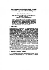
In the sequel, we investigate the performance of G-JCNC for LDPC codes. Note that the LDPC codes used in this paper are obtained from the homepage of the EPFL Information Processing Group, in Switzerland [10]. These LDPC codes are optimized for the decoder using sum-product algorithm. Fig. 9 shows the BER performance of the two schemes with different number of iterations. We use a low rate Rc = 0.188 LDPC code with the code length N = 1000. The number of iterations are set to 10, 20 and 50 for comparison, respectively. It can be observed that the proposed G-JCNC outperforms the common approach S-JCNC significantly, e.g., there is 1.5 dB gain at BER 10−3 with 20 iterations and almost 2 dB gain at BER 10−4 with 50 iterations. Specially, the performance
112
0
0
10
10
−1
−1
10
−2
−2
10
10
−3
10
S-JCNC, 10 iter. G-JCNC, 10 iter. S-JCNC, 20 iter. G-JCNC, 20 iter. S-JCNC, 50 iter. G-JCNC, 50 iter.
−4
10
−5
10
−6
10
BER
BER at the relay
10
0
1
2
−3
10
BER@R (S-JCNC) BER@R (G-JCNC) BER@A,B (S-JCNC) BER@A,B (G-JCNC) AWGN (ref.)
−4
10
−5
10
−6
Eb N0
3
4
10
5
0
1
2
in dB
Fig. 9. BER performance comparison between G-JCNC and S-JCNC with a Rc = 0.188-rate LDPC with code length N = 1000. The iteration numbers of both algorithms are set to 10, 20 and 50, respectively.
Eb N0
3
4
5
in dB
Fig. 11. BER at both sources A, B and relay R for G-JCNC and S-JCNC, where the same LDPC code with the code length N = 1000 and code rate Rc = 0.4 is used at both sources and the relay. The iteration number of both algorithms is set to 20.
0
10
0
10
−1
−1
10 −2
10
−2
10
−3
10
S-JCNC, N = 1000 G-JCNC, N = 1000 S-JCNC, N = 2000 G-JCNC, N = 2000 S-JCNC, N = 4000 G-JCNC, N = 4000
−4
10
−5
10
−6
10
0
1
2
Eb N0
BER
BER at the relay
10
−3
10
−4
10
S-JCNC 3
4
G-JCNC
−5
5
10
in dB
Fig. 10. BER performance comparison between G-JCNC and S-JCNC with a Rc = 0.25-rate LDPC with code length N = 1000, 2000 and 4000. The iteration number of both algorithms is set to 50.
of G-JCNC with 10 iterations is nearly the same as S-JCNC with 50 iterations. We now consider the influence of the code length on the BER curves for both schemes. The code length N is set to 1000, 2000 and 4000 with the same code rate Rc = 0.25 of the LDPC codes. The number of iterations is 50. Fig. 10 shows the BER performance of both schemes with respect to different code length. As observed in the figure, large code length leads to smaller BER for both schemes but with significantly increased decoding complexity. However, it can be observed that the BER performance of G-JCNC with code length 1000 is better than S-JCNC with code length 4000. Therefore, with our novel decoding approach better performance with lower complexity can be achieved. Fig. 11 shows the average BER at both source versus SNR for both schemes. It is assumed that the relay uses the same
0
1
2
Eb N0
3
4
5
in dB
Fig. 12. BER performance comparison between G-JCNC and S-JCNC for distributed MIMO multi-hop networks, where all the node use the same LDPC code with the code length 4000 and code rate 0.25. The iteration number of both algorithms is set to 50.
LDPC code as the two sources. The two sources decode the signal from the relay and extract the information from each other by simple XOR operation between the decoded bits and their transmit bits at the MAC stage. We consider a Rc = 0.4rate LDPC code with code length N = 1000 and 20 iterations. As a performance reference, we consider also the same LDPC code over an AWGN channel. It has been observed that the average BER at both sources is almost the same as the BER at the relay. The decoding process at the relay is critical to the two-way transmissions. B. G-JCNC for Distributed MIMO Multi-hop Two-Way Networks As discussed in Section IV, G-JCNC can be extended to distributed MIMO multi-hop networks. In the sequel, we
113
investigate the network consisting of 4 hops and the number of nodes within the VAAs are 3, 3 and 2, as illustrated in Fig. 6. Furthermore, within these VAAs an antenna selection criterion is considered, by which any one of the relays which are able to decode the information successfully is selected. Fig. 12 shows the average BER at both sources for S-JCNC and G-JCNC. It is assumed that all the nodes in the network use the same LDPC code with code length 4000 and code rate Rc = 0.25. From the figure, we can observed that for the distributed MIMO multi-hop networks the proposed G-JCNC achieves better performance of S-JCNC.
[8] M. Dohler, Virtual Antenna Arrays, Ph.D. thesis, King’s College London, U.K., November 2003. [9] Y. Lang, D. W¨ubben, and K.-D. Kammeyer, “Power allocations for adaptive distributed mimo multi-hop networks,” in IEEE International Conference on Communications (ICC09), Dresden, Germany, June 2009. [10] R. Urbanke, “LDPC: Optimization of LDPC Codes for BP Decoder,” online: http://ipgdemos.epfl.ch/ldpcopt/.
VI. C ONCLUSION In this paper, we have considered a two-way relay system with two sources A and B, and one relay node R, where the two sources wish to exchange information through the relay node. In order to fully exploit the information contained in ˆ A⊕B the superimposed signal yR = xA + xB + nR to decode b reliably, a novel decoding approach was presented, called generalized joint channel and network coding (G-JCNC). We have ˆ A⊕B discards observed that the decoding directly from yR to b some useful information. Hence, a virtual encoder with input bA+B and output cA+B has been constructed. The proposed decoding algorithm decodes the received signal yR to the sum ˆ A+B first and then maps b ˆ A+B of the two source information b ˆ to bA⊕B . It is inspired by the fact that cA+B contains more useful information than cA⊕B related to the decoding of bA⊕B . Note that since the decoding algorithm is based on the factor graph by using the sum-product algorithm, it is applicable to any linear channel code, e.g., Low-Density Parity-Check (LDPC) codes. Furthermore, the two-way relaying scheme was extended to distributed multiple input multiple output (MIMO) multi-hop networks. Based on an antenna selection criterion within each virtual antenna array (VAA), the endto-end (e2e) BER of the multi-hop system can be further reduced. Simulation results show that the proposed scheme GJCNC outperforms the other recently proposed network coding scheme S-JCNC. R EFERENCES [1] R. Ahlswede, N. Cai, S.-Y. R. Li, and R. W. Yeung, “Network Information Flow,” IEEE Trans. on Information Theory, vol. 46, no. 4, pp. 1204–1216, July 2000. [2] S. Zhang, S. Liew, and P. Lam, “Physical Layer Network Coding,” in Proc. International Conference on Mobile Computing and Networking (MobiCom), Los Angeles, USA, 2006, pp. 358–365. [3] S. Zhang and S. Liew, “Joint Design of Physical Layer Network Coding and Channel Coding,” ”http://adsabs.harvard.edu/abs/2008arXiv0807.4770Z”. [4] C. Hausl and J. Hagenauer, “Iterative Network and Channel Decoding for the Two-way Relay Channel,” in IEEE Proc. International Conference on Communications (ICC), Istanbul, Turkey, June 2006. [5] P. Popovski and H. Yomo, “Physical Network Coding in Two-Way Wireless Relay Channels,” in IEEE Proc. International Conference on Communications (ICC), Glasgow, Scotland, June 2007. [6] A. Zhan and C. He, “Joint Design of Channel Coding and Physical Network Coding for Wireless Network,” in IEEE Proc. International Conference on Neural Networks and Signal Processing, Zhejiang, China, June 2008. [7] F. R. Kschischang, B. J. Frey, and H. A. Loeliger, “Factor graphs and the sum-product algorithm,” IEEE Trans. on Information Theory, vol. 47, no. 2, pp. 498–519, 2001.
114