An Improved Robust Field-Weakening Control Algorithm for Direct Torque Controlled IPM Synchronous Motors X.N. Zhang1, Student Member, IEEE, Gilbert Foo1, Member, IEEE, L.M. Douglas2, Member, IEEE 1
School of Electrical & Electronics Engineering, 2 School of Computer Engineering Nanyang Technological University, Singapore. Email:
[email protected],
[email protected],
[email protected]. Abstract— Direct torque control has been widely accepted as a simple but effective control method for AC motor drives. It is robust to parameter variations since only stator resistance is used in the algorithm. However, to obtain high performance motor drives, the stability and robustness of direct torque control in the field-weakening region must be guaranteed. Some of the existing research proposals are parameter dependent. This paper proposes an improved robust field-weakening control algorithm for direct torque controlled IPM synchronous motors. The effectiveness of the proposed method is validated by simulation results. Index Terms--IPM synchronous motor; ac motor drives; direct torque control; field-weakening; system stability
I.
INTRODUCTION
In modern electric drives, direct torque control (DTC) becomes popular due to its simplicity, fast response and parameter robustness. It is applicable to different types of motors, including induction motor, synchronous motor and synchronous reluctance motor. Since rotating coordinate transformation and pulse-width-modulation (PWM) are not used in DTC, the algorithm is very simple and the information of precise rotor position is not required. This further qualifies DTC as a promising candidate for sensorless control. A substantial amount of publications have investigated the performance of DTC in induction motor drives [1-4]. Both advantages and problems of DTC are widely discussed and proposals are provided to improve the drive performance [5-8]. In recent years, the interior permanent magnet (IPM) synchronous motor (SM) has attracted extensive research attentions due to its high energy density and high efficiency. Consequently, the application of DTC to IPMSM is proposed by many researchers. To obtain high quality IPMSM drives, the performance of direct torque control in high speed region must be investigated. This is especially meaningful for applications of electric vehicles and hybrid electric vehicles which require a wide speed range.
F. Rahman3, Senior Member, IEEE
3
School of Electrical Engineering and Telecommunications, University of New South Wales, Sydney, Australia. Email:
[email protected].
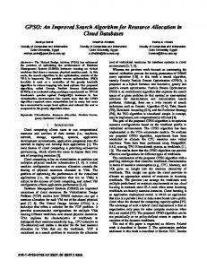
One of the most significant problems associated with DTC in high speed region is the instability caused by fieldweakening operations. Generally, the maximum torque per ampere (MTPA) algorithm is used to regulate the flux amplitude for efficiency optimization [11]. However, when the motor speed is increased above the base speed, the stator voltage approaches the maximum limit imposed by the available DC-link voltage. Consequently, the torque and flux controllers become saturated and the controllability will be lost if MTPA algorithm continues to dominate. Under such circumstances, modifications have to be made to improve the stability and robustness of DTC. Research proposals for DTC based field-weakening operations are given in [7]-[10]. The majority of these proposals focuses on the field-weakening methods of directtorque-controlled induction motors and is not readily applicable for the IPMSM. Moreover, parameter dependency is still a problem. In [12], an optimum trajectory control for nonsalient-pole PMSM is proposed for field-weakening operation. However, it is complicated and is not suitable for IPMSM drives. Reference [13] presents a control strategy that can satisfy both the voltage and the current limits for direct-torque-controlled PMSM. Nonetheless, the fieldweakening algorithm is derived in the stator reference frame and PWM is used for motor drives. This increases the computational cost and complexity. This paper proposes a field-weakening algorithm for direct-torque-controlled IPMSM in the stationary reference frame. It modifies the reference of stator flux and torquelimit based on the analysis of torque errors. Furthermore, the proposed method is robust to parameter variations because the conventional base speed computation is not necessary. The block diagram of the detailed control strategy is shown in Fig. 1. The mathematical model of IPMSM in the rotor flux reference frame is given in (1). Generally, the steady-state stator voltage and current vectors can be expressed in phasor diagram as shown in Fig. 2 [14]. It is noted that β is the angle between stator current vector and the q-axis. Therefore, the dq-axes current components can be expressed as in (2) where
Is represents the magnitude of stator current vector. The electro-magnetic torque of IPMSM is given in (3). ω ref
T ref
+
−
ωe
τ
+
−
−Δτ
ϕ ref
min ( A , B )
b
1
2 0 Δτ b 2
ϕ
+
−
S 3 (010
Δτ
)
S 2 (110 )
S 1 (100
S 4 (011 )
)
1 0
S 5 (001 )
Δϕ
Δϕb
Δτ
S 6 (101
θ re
)
θ
Sx
ϕ
Vdc
T
iα
ia
αβ
iβ
ib
abc
d dt
Fig. 1. Block diagram of the proposed field-weakening algorithm for IPMSM with DTC.
II.
MATHEMATICAL MODEL OF IPMSM AND MAXIMUM TORQUE-PER-AMPERE (MTPA) TRAJECTORY
ω re Lq ⎤
⎡ Rs ⎡• ⎤ ⎢ − L i d ⎢•d ⎥ = ⎢ ⎢i q ⎥ ⎢ − ω re Ld ⎣ ⎦ ⎢ Lq ⎣
Ld R − s Lq
⎥ ⎡i ⎤ ⎡ 0 ⎥ ⎢ d ⎥ + ⎢ ωreϕ f ⎥ ⎣ iq ⎦ ⎢ − L q ⎣ ⎥ ⎦
⎡ vd ⎤ ⎤ ⎢ ⎥ ⎥ + ⎢ Ld ⎥ ⎥ ⎢ vq ⎥ ⎦ ⎢L ⎥ ⎣ q⎦
(1)
q − axis vs
ωreϕ f
ris
is iq
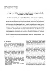
By equating the derivative of (4) to zero, the condition for developing the maximum motor torque is derived and is shown in (5). Apparently, the maximum torque can be obtained if the reference trajectory of flux controller is set to (5). However, the MTPA trajectory defined by (5) is in the rotor flux reference frame. It increases the difficulty of realtime implementation because DTC is implemented in stationary reference frame. Consequently, it is necessary to find out the relationship between the torque and the amplitude of stator flux that satisfies the MTPA trajectory. This relationship is usually determined numerically as illustrated in Fig. 3. In real-time, look-up-table is utilized to implement the MTPA algorithm.
id =
ϕs
β
ϕf
2(Lq − Ld )
ϕ 2f
−
4(Lq − Ld )
2
+ iq2
(5)
7
id
ϕf
d − axis
6 5 4
Fig. 2. Phasor diagram of stator voltage and current vectors of IPM synchronous motor.
id = − I s sin β iq = I s cos β
Te =
[
3 Pp ϕ f iq + (Ld − Lq )id iq 2
2 1
(2)
]
(3)
By substituting (2) into (3), the expression of motor torque with respect to the amplitude of stator current is derived and is shown in (4). The first and second terms of (4) are characterized as excitation torque and reluctance torque respectively. It is obvious from (4) that the maximum torque can be obtained by controlling Is and β appropriately.
Te =
3
3 3 Ppϕ f I s cos β + Pp (Lq − Ld )I s2 sin 2β 2 4
(4)
0 0.2
0.4
0.6
0.8
1
ϕs
Fig. 3. Characteristic curve of torque and magnitude of stator flux.
In fact, the MTPA trajectory may not be traceable under all operating conditions of motoring, especially in the high speed regions. This is because the current and voltage limits imposed by the motor/inverter and DC-link voltage must be satisfied to ensure the stability of drives. For better illustration, the current and voltage constraints are expressed in the rotor flux reference frame as shown in (6). According to the steady-state stator voltage equation of (7), the steadystate voltage limit can be derived as shown in (8). If the stator resistance is neglected, the approximate voltage limit condition will be in the form of (9). From the right part of
inequality (9), it can be seen that the effective stator voltage limit trajectory contracts with the increase of motor speed. Consequently, in the high speed region, the MTPA trajectory might exceed the boundary of voltage and current limits. Under such circumstances, the MTPA control has to be replaced by field-weakening control to maintain stable operation.
when τ = 1 and is rotated reversely when τ = 0 . The amplitude of stator flux linkage can be increased or decreased by setting φ to 1 or 0 respectively. Consequently, it is seen that the control of torque is realized by regulating τ and the control of stator flux amplitude is achieved by regulating φ . TABLE I. SWITCHING TABLE OF DIRECT TORQUE CONTROL
2 d
2 q
I s = i + i ≤ I s (max )
(6)
Vs = vd2 + vq2 ≤ Vs ( max )
− ωre Lq ⎤ ⎡id ⎤ ⎡ 0 ⎤ ⎢ ⎥+⎢ ⎥ Rs ⎥⎦ ⎣iq ⎦ ⎣ωreϕ f ⎦
⎡vd ⎤ ⎡ Rs ⎢v ⎥ = ⎢ ⎣ q ⎦ ⎣ωre Ld
(R i
s d
φ (7)
− ωre Lqiq ) + (Rsiq + ωre Ld id + ωreϕ f ) ≤ Vs (max ) 2
(8)
(L i ) + (L i 2
q q
d d
+ϕf )
2
⎛V ⎞ ≤ ⎜⎜ s (max ) ⎟⎟ ⎝ ωre ⎠
τ
θ
θ (1)
θ (2)
θ (3)
θ (4)
θ (5)
θ (6)
τ =1
V2 (110) V3 (010) V4 (011) V5 (001) V6 (101) V1 (100)
τ =0 τ =1 φ =0 τ =0
V6 (101) V1 (100) V2 (110) V3 (010) V4 (011) V5 (001)
φ =1
V3 (010) V4 (011) V5 (001) V6 (101) V1 (100) V2 (110) V5 (001) V6 (101) V1 (100) V2 (110) V3 (010) V4 (011)
B. Field-weakening Algorithm based on Consecutive Torque Error Analysis
2
(9)
Based on the above discussion, field-weakening control is necessary for high speed motor drives. Moreover, the constraints imposed by the current and voltage limits must be clearly defined for control mode switching. In general, the motor speed for switching from MTPA to field-weakening control is defined as base speed. However, in real-time DTC, there are two problems with control mode switching according to the base speed. Firstly, the base speed is usually computed on the basis of steady-state equations. Thus, it is not very accurate for real-time control. Secondly, the calculation of base speed requires the knowledge of machine parameters. This means the base speed expression is parameter-dependent. Since the starting point of control mode switching is very important for field-weakening control and the stability of drive systems, improvement on the determination of base speed is necessary.
The proposed field-weakening algorithm modifies the references of torque and stator flux on the basis of consecutive torque error analysis. It checks whether the reference torque trajectory can be satisfied for a number of consecutive sampling cycles. The result of analysis is used as the criterion of control mode switching between MTPA control and field-weakening control. In the field-weakening region, the references of torque and flux are adjusted in a consecutive manner to maintain the stability of drives. Details of this algorithm are explained below.
CNT_ N =CNT_ N +1
Δ τ (k ) > 0 CNT_ϕ = CNT_ϕ +1
CNT _ ϕ = CNT _ ϕ
III. DESCRIPTION OF THE PROPOSED FIELD-WEAKENING ALGORITHM
CNT_ N = Nϕ _limit
A. Direct Torque Control Algorithm To solve the stability problems of direct torque controlled IPMSM in the field-weakening regions, this paper proposes an improved robust DTC algorithm. The basic idea of the proposed algorithm is to modify the stator flux reference and the torque-limit according to the real-time torque errors. For better understanding of the proposed algorithm, the conventional DTC algorithm is briefly reviewed in this part. As shown in Fig. 1, the reference torque is the output of speed PI regulator and the reference flux is generated from the MTPA look-up-table based on the reference torque. The torque and flux errors are given to the corresponding hysteresis controllers for choosing one of the six active space vectors listed in Table I where the sector of the stator flux vector is denoted as θ(i) [14]. It is noted that τ and φ are used to control the rotation direction and the amplitude of stator flux linkage respectively. Generally, the stator flux linkage vector is rotated in the counter clockwise direction
ϕ _ adj (k ) = ϕ _ adj (k − 1)
CNT _ϕ = Nϕ _ limit ϕ _ adj(k ) = ϕ _ adj(k −1) − Δϕ
CNT_ N = CNT_ N
ϕ _ adj(k ) = ϕ _ adj(k −1) + Δϕ
CNT _ N = 0
CNT _ N = 0
CNT _ ϕ = 0
CNT _ ϕ = 0
CNT_ϕ = CNT_ϕ
ϕ _ adj
Fig. 4. Flow chart of the proposed flux reference adjustment algorithm.
When an IPMSM is operating in the low speed region, the reference torque is traceable by directly applying one of the six active voltage vectors. This is because the applied stator voltage is still below voltage limit. Consequently, the sign of torque error will be varying every a few sampling cycles according to the hysteresis principle. However, when the speed of IPMSM is increased above the base speed, the
choice of reference flux trajectory is determined by the rotor speed and the load. Usually, when the motor is loaded and is operating at high speeds above the base speed, the fieldweakening trajectory has to be used instead of MTPA. The intersection of MTPA trajectory and field-weakening trajectory is the point where stator voltage reaches its maximum limit. If the rotor speed is further increased after the intersection point and MTPA is still used, the actual torque will be unable to reach the reference torque. This means the sign of torque error will remain unchanged. Based on the above discussion, the sign of torque error within a sufficient number of sampling cycles can be used to check the point of control mode switching, namely the starting point of field-weakening control. This is illustrated in detail in Fig. 4 where CNT_N and CNT_φ represent the counter of consecutive sampling cycles and the counter of reference flux respectively. The maximum limit of both of the two counters is defined as Nφ_limit. It is used as the threshold of base speed identification as shown in Fig. 4. A reasonable value of Nφ_limit can be found by using computer simulations. In this paper, Nφ_limit is chosen as 40. In each sampling cycle, the number of torque control failures will be updated and compared with Nφ_limit. If consecutive torque control failures are detected for Nφ_limit times, it means the flux reference is too large and can not be tracked without field-weakening. Thus, adjustment should be made on the flux reference as shown in Fig. 4. On the consideration of control stability and fast convergence, a saturation limit is added at the output of flux adjustment. In practice, the adjusted flux reference for field-weakening control is compared with the conventional MTPA trajectory. The smaller value of them will be selected as the final flux reference as shown in Fig. 5.
min ( A , B )
ϕ ref
Vdc + ϕ _ adj (k ) 3 ωre Fig. 5. Proposed algorithm for reference flux calculation.
C. Torque-limiting operation
Algorithm
for
field-weakening
To achieve stable field-weakening operation, attentions should also be given to the torque-limits imposed by the voltage and current limitations. This is because the maximum torque capability can not be exceeded by the torque reference. Otherwise, torque control failures will happen and the drive system will eventually run out of control. In order to guarantee the stability of torque control, dynamic torque limits have to be added to the control system. In general, there are two torque-limits imposed by inverter/motor current limitation and DC-link voltage limitation. The first torque-limit can be derived on the basis of power equivalence as shown in (11) where Vs and Is represent the amplitudes of stator voltage and stator current respectively. Notation Tr is the reactive torque as expressed in (12). During steady-state operations, the maximum amplitude of stator voltage can be approximated by (13). Substitute (13) into
(11) and re-arrange the terms, the torque-limit satisfying current limitation can be derived as shown in (14). In (14), Is_max represents the maximum amplitude of stator current imposed by inverter/motor. 2
⎞ ⎛3 2 2 ⎜ Vs I s ⎟ = (Teω m ) + (Tr ω m ) ⎝2 ⎠
(11)
3PP (λsα isα + λsβ isβ ) 2
(12)
Vs _ max = λ∗s ω re = λ∗s Pp ω m
(13)
Tr =
2
Te _ c lim =
⎛3 2 ∗⎞ ⎜ PP I s _ max λs ⎟ − (Tr ) ⎝2 ⎠
(14)
The torque-limit in (14) can be used to extend the speed range to satisfy field-weakening requirement. However, when the motor speed is further increased above the crossover speed, the other torque-limit imposed by the maximum torque per flux (MTPF) control has to be used. This can be vividly illustrated by Fig. 6. From Fig. 6, it is clearly seen that the intersection of MTPA and current limit trajectories is defined as the base speed ωb. Similarly, the intersection of current limit and MTPF trajectories is defined as the crossover speed ωc [15]. Speed operation region is divided into three sub-regions by ωb and ωc. In the first sub-region, rotor speed is smaller than ωb and the voltage limit will be satisfied on condition that MTPA trajectory satisfies the current limit. Thus, field-weakening is not necessary. In the second sub-region, the rotor speed is between ωb and ωc. Therefore, the current limit trajectory has to be used for fieldweakening control. In the third sub-region, the rotor speed exceeds ωc and MTPF control should be utilized to obtain higher speed. In real-time, this is implemented by dynamic torque-limit expressed in (15) where Pp and φf represent the number of pole pairs and the rotor flux respectively. It is apparently seen that the torque-limit in (15) is dependent on machine parameters and should be implemented by using the look-up-table in real-time control. In practice, this is not desirable from the viewpoint of parameter robustness. 10 ω = ωb
ω = ωc
8 ωb < ω < ωc
ω > ωc
ω < ωb
6
4
2
ϕs = ϕ f 0 0
0.1
0.2
ϕs = ϕsr 0.3
0.4
0.5
0.6
Fig. 6. Control trajectory in torque-flux plane.
0.7
ϕs
⎧ (L − Ld ) ⎡⎢ϕ − ϕ 2 + 8⎛⎜1 − Ld ⎞⎟ϕ 2 ⎪ϕ d = q f f ⎜ L ⎟ ref ⎪ 4 Lq ⎢ q ⎠ ⎝ ⎣ ⎪ ⎪ 2 ϕ q = ϕ ref − ϕ d2 ⎨ ⎪ 3Pp ⎡ϕ f ⎛ 1 1 ⎞ ⎤ ⎪ T ⎢ + ⎜⎜ − ⎟⎟ϕ d ⎥ϕ q e _ v lim = ⎪ 2 ⎢⎣ Ld ⎝ Lq Ld ⎠ ⎥⎦ ⎪⎩
⎤ ⎥ ⎥ ⎦
(15)
IV. SIMULATION RESULTS
As discussed above, the conventional torque-limit imposed by MTPF control is sensitive to the machine parameters. To improve its robustness, this paper proposes an adjustment algorithm for the torque-limit in (15). The mechanism of this algorithm is given in Fig. 7. It is noted that the proposed torque-adjustment algorithm is also based on torque error analysis. Counter CNT_T is utilized to count the number of positive torque errors. It is incremented whenever a positive torque error is detected and is reset back to zero on the detection of negative torque error. As a result, if the value of CNT_T becomes equivalent to a sufficiently large number, it means the reference torque has exceeded the maximum torque capability. In such situations, the reference torque must be reduced until the electromagnetic torque becomes under control again. In this paper, the threshold number of CNT_T is defined as NT_limit. A suitable value of NT_limit can be found by computer simulations. Here, it is set to 30. For stable operations, a saturation limit is also added to the output of torque-limiting algorithm as shown in Fig. 7. Sampling Interrupt
Δ τ (k ) > 0
Yes
No
CNT_T = CNT_T +1
CNT _ T = NT _ limit
No
CNT_T = CNT_T
CNT_T = CNT_T
Torque (Nm)
CNT_T = CNT_T
T _ adj (k ) = T _ adj (k − 1)
Saturation Limit T _ adj
Fig. 7. Flow chart of the proposed torque-limit adjustment algorithm.
λ ∗s
Te _ clim =
(P λ I
) −T
2 ∗ p s s _ max
2 r
λ ∗s ∗
T _ adj Te _ v lim = LUT ( λs ) + T _ adj
T ref −1
Pp
2
Stator resistance
Rs
5.5 Ω
Rotor flux linkage
φf
0.297 Wb
d-axis inductance
Ld
0.0868 H
q-axis inductance
Lq
0.1697 H
Maximum motor current
Imax
5A
DC-link voltage
Vdc
140 V
5000 4000 3000 2000 1000 0 0.5 0.4 0.3 0.2 0.1 0 3.5 3 2.5 2 1.5 1 0.5 0
0.5
1
1.5
2
2.5
3
3.5
4
4.5
5
0.5
1
1.5
2
2.5
3
3.5
4
4.5
5
0.5
1
1.5
2
2.5
3
3.5
4
4.5
5
Time (s) Fig. 9. IPMSM acceleration with the proposed field-weakening algorithm. subplot 1: reference speed (red), rotor speed(blue); subplot 2: reference flux(red), stator flux(blue); subplot 3: reference torque(red), electromagnetic torque(blue).
Tr Is _ max
Number of pole pairs
The simulation result of IPMSM acceleration from 300rpm to 5000 rpm under no load condition is shown in Fig. 9. Stable and smooth transition between MTPA control and field-weakening control is observed with the proposed algorithm. It is worth mentioning that the automatic detection of base speed has significantly improved the robustness of field-weakening control.
Flux (Wb)
T _ adj(k ) = T _ adj(k − 1) − ΔT
Yes
TABLE II. PARAMETERS OF IPMSM SYSTEM
Yes
CNT_T = 0 T _ adj(k ) = T _ adj(k − 1) + ΔT
To verify the effectiveness of the proposed algorithm, an IPMSM drive system is built in MATLAB/SIMULINK environment. Parameters of the IPMSM drive system are given in Table II. The simulation results are provided and discussed in this section.
Speed (rpm)
CNT_T = 0
No
In the proposed field-weakening control algorithm, the reference torque is generated as shown in Fig. 8 which incorporates the afore-mentioned two torque-limits and the torque adjustment. It should be noticed that the look-up-table (LUT) in Fig. 8 is based on the relationship in (15).
−1
Fig. 8. Proposed algorithm for reference torque calculation.
To test the parameter robustness of the proposed fieldweakening algorithm, two simulations are carried out with intentionally detuned Ld and Lq values. The first simulation is implemented with 30% decrease of Ld and the second simulation is implemented with 30% decrease of Lq. Both of the two simulations are carried out under the same scenario of Fig. 9. The corresponding result is given in Fig. 10 and
Fig. 11 respectively. It is observable that the performance of field-weakening operation is not apparently affected by the detuned parameters. This means the proposed algorithm is robust to machine parameter variations. This is very desirable in real-time applications. 5000 4000 3000 2000 1000 0 0.5 0.4 0.3 0.2 0.1 0 3.5 3 2.5 2 1.5 1 0.5 0
3.5 3 2.5 2 1.5 1 0.5 0
[2]
[4] 0.5
1
1.5
2
2.5
3
3.5
4
4.5
5
[5]
0.5
1
1.5
2
2.5
3
3.5
4
4.5
5
[6]
[7]
1
1.5
2
2.5
3
3.5
4
4.5
5
Fig. 10. IPMSM acceleration under 30% decrease of Ld with the proposed field-weakening algorithm. subplot 1: reference speed (red), rotor speed(blue); subplot 2: reference flux(red), stator flux(blue); subplot 3: reference torque(red), electromagnetic torque(blue).
0.5 0.4 0.3 0.2 0.1 0
[1]
[3]
0.5
5000 4000 3000 2000 1000 0
REFERENCES
[8]
[9]
[10] [11] 0.5
1
1.5
2
2.5
3
3.5
4
4.5
5
[12]
[13] 0.5
1
1.5
2
2.5
3
3.5
4
4.5
5
[14] [15] 0.5
1
1.5
2
2.5
3
3.5
4
4.5
5
Fig. 11. IPMSM acceleration under 30% decrease of Lq with the proposed field-weakening algorithm. subplot 1: reference speed (red), rotor speed(blue); subplot 2: reference flux(red), stator flux(blue); subplot 3: reference torque(red), electromagnetic torque(blue).
V.
CONCLUSION
This paper proposes an improved robust field-weakening algorithm for direct torque controlled IPM synchronous motors. It achieves stable operation in a wide speed range and is robust to parameter variations. The proposed algorithm modifies the flux reference and torque-limit based on the analysis of torque error. It is simple from the viewpoint of mathematical computations, and thus, is suitable for real-time high frequency digital control systems. The effectiveness of the proposed algorithm is verified by simulations.
I. Takahashi, Y. Ohmori, “High-performance direct torque control of an induction motor,” IEEE Transactions on Industry Applications, vol. 25, no. 2, pp. 257 - 264, Mar/Apr 1989. T. Abe, T.G. Habetler, F. Profumo, G. Griva, “Evaluation of a high performance induction motor drive using direct torque control,” Conference Record of the Power Conversion Conference, pp. 444 449, April 1993. J.N. Nash, Milwaukee, “Direct torque control, induction motor vector control without an encoder,” IEEE Transactions on Industry Applications, vol. 33, no. 2, pp. 333 - 341, Mar/Apr 1997. Hoang Le-Fleuy, “Behavioral modeling and simulation of a directtorque-control induction motor drive using PSPICE,” IECON '99 Proceedings, vol. 43, pp. 1403 - 1408, 1999. C. Lascu, I. Boldea, F. Blaabjerg, “Direct torque control of sensorless induction motor drives a sliding-mode approach,” IEEE Transactions on Industry Applications, vol. 40, no. 2, pp. 582 - 590, March-April 2004. Shyu Kuo-Kai, Lin Juu-Kuh, Pham Van-Truong, Yang Ming-Ji, Wang Te-Wei, “Global Minimum Torque Ripple Design for Direct Torque Control of Induction Motor Drives,” IEEE Transactions on Industrial Electronics, vol. 57, no. 9, pp. 3148 - 3156, Sept. 2010. D. Casadei, G. Serra, A. Stefani, A. Tani,L. Zarri, “DTC Drives for Wide Speed Range Applications Using a Robust Flux-Weakening Algorithm,” IEEE Transactions on Industrial Electronics, vol. 54, no. 5, pp. 2451 - 2461, Oct. 2007. E. Levi, Wang Mingyu, “A speed estimator for high performance sensorless control of induction motors in the field weakening region,” IEEE Transactions on Power Electronics, vol. 17, no. 3, pp. 365 - 378, May 2002. Choi Chan-Hee, Seok Jul-Ki, R.D. Lorenz, “Wide-Speed Direct Torque and Flux Control for Interior PM Synchronous Motors Operating at Voltage and Current Limits,” IEEE Transactions on Industry Applications, vol. 49, no. 1, pp. 109 - 117, Jan.-Feb. 2013. P. Matić, S.N. Vukosavić, “Voltage angle direct torque control of induction machine in field-weakening regime,” IET Electric Power Applications, vol. 5, no. 5, pp. 404 - 414, May 2011. S. Bolognani, L. Peretti, M. Zigliotto, “Online MTPA Control Strategy for DTC Synchronous-Reluctance-Motor Drives,” IEEE Transactions on Power Electronics, vol. 26, no. 1, pp. 20 - 28, Jan. 2011. R. Nalepa, T. Orlowska-Kowalska, “Optimum Trajectory Control of the Current Vector of a Nonsalient-Pole PMSM in the FieldWeakening Region,” IEEE Transactions on Industrial Electronics, vol. 59, no. 7, pp. 2867 - 2876, July 2012. Y. Inoue, S. Morimoto, M. Sanada, “Control Method Suitable for Direct-Torque-Control-Based Motor Drive System Satisfying Voltage and Current Limitations,” IEEE Transactions on Industry Applications, vol. 48, no. 3, pp. 970 - 976, May-June 2012. Zhong Limin, “high performance torque and field weakening controllers for interior permanent magnet synchronous motors,” P.h.D Thesis, University of New South Wales, 1999. M. E. Haque, L. Zhong and M. F. Rahman, “Improved trajectory control for an interior permanent magnet synchronous motor drive with extended operating limit,” Journal of Electrical and Electronics Engineering, Australia, vol. 22, no. 1, pp. 49 - 57, 2002.