TELKOMNIKA, Vol.11, No.11, November 2013, pp. 6631~6636 e-ISSN: 2087-278X
6631
An Improved Variable-Frequency Drive based on Current Tracking Zhiwei He*, Guangyan Zhou, Mingyu Gao Dept. of Electronic Information, Hangzhou Dianzi University, China *Corresponding author, e-mail:
[email protected]
Abstract Variable frequency devices are widely used in many power systems. A current tracking based VFD is proposed in this paper. The output current is firstly fed back and compared with a standard sine wave, the difference of them is then used for a PI regulator to control the PWM signal, so as to change the output current accordingly to make it approach the standard sine wave. Simulation and experiments results show that the current tracking VFD not only has a fast dynamic response, high current tracking precision, current limiting ability, but also has small distortion of the output sine wave current and low loss of the motor. Keywords: current tracking, VFD, PWM, PI control Copyright © 2013 Universitas Ahmad Dahlan. All rights reserved.
1. Introduction Nowadays, variable frequency devices (VFD) are widely used in many power systems, such as mechanical drive systems and control systems. It is important to improve the control strategy to make it adaptable to different situations. The frequency variation method can be divided to two types: the voltage controlled frequency variation and the current controlled frequency variation [1]. Voltage frequency transformation (V/F) is one of the widely used voltage controlled frequency variation methods [2]. There are two most commonly used modulation modes for V/F: the sinusoidal pulse width modulation (SPWM) and the space vector pulse width modulation (SVPWM) [3]. SPWM can basically meet the requirements in transmission, and it is also the most widely used method in VFD, but when the motor runs at a low frequency, the maximum output torque decreases [4]. The purpose of SVPWM is to generate motor circular magnetic field trajectory, which can improve the voltage utilization, but SVPWM can not adjust the torque conveniently [5]. Conventional voltage controlled VFD has bad performance on dynamic response and steady state accuracy of the output current. What’s more, the waveform distortion of the output sinusoidal current is serious, which contains a lot of high-frequency harmonics [6], resulting in a decline of efficiency for the motor. Vector control [7-9] is a high-performance current controlled frequency variation method. The vector control method uses Park transformation, Clarke transformation, inverse Park transformation and inverse Clarke transformation to decompose the stator current and get covariant with torque and magnetic field [10]. However, this method depends a lot on the parameters of the motor [11], moreover, the rotor flux can not be measured accurately. For these reasons, the actual performance of the vector control based method is not good. As mentioned before, voltage controlled VFDs may not provide sufficient torque for the motor, the current controlled VFD is studied in this paper. A current tracking based control method for VFD is proposed. This method controls the output current of the VFD directly, so the VFD can control the motor output torque more easily, it can also be effective in preventing the occurrence of VFD’s over-current, and reducing the current fluctuations during the acceleration and deceleration process. The basic idea of the current tracking method is to track the given sine wave signal based on the motor load, and then change the amplitude or frequency of the given sine wave. For implementation, a three-phase stator current is firstly gotten and compared with the given Received April 18, 2013; Revised June 22, 2013; Accepted July 23, 2013
6632
e-ISSN: 2087-278X
current signal. The bias current is then calculated, which is then put through a ProportionIntegration regulator. The PWM duty cycle of the inverter part is then regulated to make the three-phase stator current approach the given current signal gradually. The current tracking control of the VFD actually constitutes a current closed-loop control system.
2. Principle of Current Tracking The current tracking VFD system contains five parts: the current waveform generation part, the PI regulator, the PWM part, the inverter and the motor, the first three belong to control part, and last two belong to power part, all of these form a current closed loop feedback system. The framework of the system is shown in Figure 1. In the diagram, PWM1 to PWM6 represents 6 PWM signals input to inverter part, U, V and W represent 3 output voltages of the three-phase bridge, M represents an induction machine. In the current waveform generation module, 3 sine waves are generated as the standard three phases by a 32-bit microcontroller, the phase difference between each two phases is 120 o . iw* and iv* are the two output currents of the VFD, which are measured by hall current sensors. The three currents satisfy that iu* + iv* +iw* = 0, so the third phase current can be obtained by the formula: iu* = -iv* -iw*. The proportional-integral regulator (PI regulator) uses the two feedback currents and the three standard sine signals to calculate a new duty cycle for each bridge.
Figure 1. The Framework of whole System
Give one of the phases U as an example. If the given standard sinusoidal current signal is iu, while the actual output current signal is iu*. In each PWM cycle’s interrupt, the actual signal is compared with the given signal, and the current deviation iu is obtained. When iu is passed through an anti-windup PI regulator, the inverter’s duty cycle is changed, so as to adjust the output current. The current tracking diagram is shown in Figure 2. As seen from the figure, the higher the sampling frequency is, the closer the actual output current waveform to the standard sine wave, and also the higher the accuracy for the current control.
Figure 2. Current Tracking Diagram
In practical applications, the motor will sometimes start quickly or decelerate rapidly, and then the traditional PI regulator’s instantaneous output deviation is too large to saturation, resulting in a system shock, increasing of adjustment time and degradation of the performance of the PI controller. In order to eliminate the adverse impact of such integral saturation, the antiwindup PI regulator is introduced here, as shown in Equation (1). TELKOMNIKA Vol. 11, No. 11, November 2013: 6631 – 6636
TELKOMNIKA
e-ISSN: 2087-278X
k U K p e k K I e j u 0 j0 u (U u max ) max u k u min (U u min ) U
6633
(1)
Where K p is the proportional coefficient, K I is the integral coefficient, ek is the deviation value of the k-th sampling time input, u0 is the initial value when the PI controller starts working, u k is the output value of the k-th sampling time, u max is the maximum limit amount of control, u min is the minimum limit amount of control. 3. Matlab Simulation of the Enter VFD System The proposed entire system was modeled and simulated with MATLAB/SIMULINK. It includes two parts: the power part and the control part, whose connection relationship is shown in Figure 1. The diagram for the power part is shown in Figure 3, which contains 6 IGBTs and an induction machine. The DC bus voltage is 310V, the induction machine is set to be a squirrelcage three-phase asynchronous motor, the stator resistance is 1.405 ohms, the rotor resistance is 1.395 ohms, the stator inductance is 5.8mH, the rotor inductance is 5.8mH, the power of the system is 4kW (actual VFD system’s power is 400W, 4KW is the smallest power model of motor in SIMULINK), and the given torque to motor is 10N.m. The output terminals of the three-phase stator current are Ia, Ib, Ic, which are used for feedbacks to the control part to control current closed-loop.
Figure 3. Simulation Diagram of the Power Part
The diagram for the control part is shown in Figure 4. The control part contains three modules: the current waveform generation module, the PI regulator module, and the PWM module. The applied modules, along with their parameters are shown in Table 1. The current waveform generation module is used to generate standard sinusoidal current signals. Each of the PI regulator modules uses the error between the given sinusoidal current and the feedback current signal as the input, and outputs an adjust value according to the PI algorithm as shown in Equation (1). Then a constant value of 500 is added in to control the CCRx to be in the range of 0 to 1000, which is more convenient to be compared with the value of counter. When the value of CCRx minus the value of the counter is greater than or equal to 5, the hysteresis comparator (Relayx in the figure) outputs 1. When the value of CCRx minus, the value of the counter is less than or equal to -5, the hysteresis comparator outputs is 0. The output of the hysteresis comparator can finally form a pair of complementary signals, with the help of a logic inverter, to drive one of the half-bridge.
An Improved Variable-Frequency Drive based on Current Tracking (Zhiwei He)
6634
e-ISSN: 2087-278X Table 1. Simulation Module and Parameter Descriptions
Simulink module (x = 1,2,3) SineWavex PI_regulatorx Cx
parameter descriptions of module 0
Amplitude is 5, frequency is 50Hz, the phase difference between the two phases is 120 . With output limit, Output Range is [-500,500], Proportionality coefficient is 0.5, Integral coefficient is 0.1. Constant.
Counterx
Maximum value is 1000, Sampling time is 1/5000000.
Subtractx
Logic Subtract.
Relayx Logicalx
Hysteresis comparator, switch on point is 5, switch off point is -5. Logic inverter.
Figure 4. Simulation Diagram of the Control Part
The simulated output currents of the VFD are shown in Figure 6. As seen from the figure, the currents can be tracked within 5ms. A comparison of the standard sine wave to the output current is shown in Figure 7, which shows that the waveform of the output current is very good. The frequency analysis of the output is shown in Figure 8. As seen from Figure 8, the fundamental frequency of the output current is 50Hz, the frequency of the carrier is 5kHz. In addition to the fundamental signal and the carrier, many harmonic components of the carrier exist, but their magnitudes decrease rapidly with the increase of the frequency. The total harmonic distortion is only 1.57%, which is very low.
Figure 6. Waveform of the Simulated Current
Figure 7. Current Tracking Result
TELKOMNIKA Vol. 11, No. 11, November 2013: 6631 – 6636
TELKOMNIKA
e-ISSN: 2087-278X
6635
The closed-loop current control strategy can control the amplitude and phase of the motor stator current conveniently and precisely. The simulated waveform of adjusting the current from 5A to 3A is shown in Figure 9. The speed of adjustment is related to the parameters of the PI regulator. With a proper set of parameters, the adjust time can be less than 5ms, as shown in Figure 9, which shows that the performance of the PI regulator is satisfactory.
Figure 8. Frequency Analysis of the Output Current
Figure 9. Current Waveform Adjustment
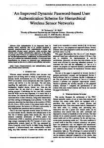
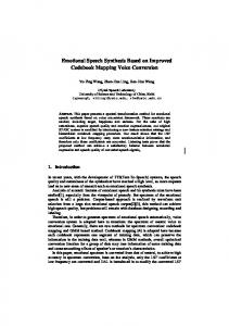
4. The Practical Results A 0.4kW VFD is designed according to the proposed control algorithm. The whole system is divides into two boards, the control board and the power board. The control board is shown in Figure 10, which is the core part of the whole VFD system. The selected MCU is ST Company’s STM32F103, which has a high speed and precise computation. The power board is shown in Figure 11. It supplies different voltages required by the system, and provides power output to the motor. The hall current sensors are selected to be ACS712, which can measure the output current precisely and fast. The power output part uses an intelligent power module (IPM), which integrates 6 IGBTs, the drive circuits, and the protective circuits together. So, it is very simple and reliable to use it. The actual waveform of the asynchronous motor’s phase current is shown in Figure 12. The sampling frequency is 5kHz and the RMS value of the current is set to be 0.5A. In Figure 12(a) on the left, horizontal axis represents signal’s time, and vertical axis represents signal’s amplitude. One grid on horizontal axis represents 10.0ms, and one grid on vertical axis represents 5.00mv, we can see from the figure that t 20ms , a 15mv , the RMS of current is about 5.3mv, and the current probe ratio is 1:100 (0.01V / A), so the RMS of actual current is 0.53A, and frequency is 50Hz. In Figure 12(b) on the right, the only difference is that one grid on horizontal axis represents 50.0ms, so the frequency is 10Hz, and the RMS of actual current is as same as the figure on the left is about 0.5A. In both figures, we can see some spurs around the waveforms; it is disturbed by strong magnetic field generated in power part. So, as seen from the figure, the current is tracked pretty well.
Figure 10. Control Board In VFD System
Figure 11. Power Board In VFD System
An Improved Variable-Frequency Drive based on Current Tracking (Zhiwei He)
6636
e-ISSN: 2087-278X
(a) 50Hz waveform
(b) 10Hz waveform
Figure 12. Actual Phase Current Waveform
5. Conclusion A closed-loop current tracking VFD with a PI controller is proposed. The 32-bit MCU STM32F103 is used to implement the control algorithm. Current signals are collected by hall current sensors and fed back to the MCU, which computes the standard sine signal, regulates output through a PI regulator, and generates 6 PWM signals in real time. With simulation and experimental verification, the current tracking VFD is proved to have good performance on the current closed-loop control. Not only fast dynamic response, high accuracy of current track, and current limiting ability is achieved, but also the advantages of small distortion with sine wave current, low loss of motor, and simplicity in control are obtained. Obviously the proposed VFD has better performance than traditional voltage-controlled VFD.
Acknowledgment This work was supported by Science and Technology Program of Zhejiang Province Grant #2012C21049, and Zhejiang Educational Committee Foundation of China Grant #Z201122745.
References [1] Jones B. VFD control methodologies in High Pressure Grinding drive systems. Cement Industry Technical Conference. Roanoke. 2012: 1-7. [2] Ben-Brahim L. Improvement of the stability of the V/f controlled induction motor drive systems. Proceedings of the 24th Annual Conference of the IEEE on Industrial Electronics Society. Doha. 1998; 2: 859-864. [3] Deshpande V, Chaudhari JG, Jagtap PP. Development and Simulation of SPWM and SVPWM Control Induction Motor Drive. 2nd International Conference on Emerging Trends in Engineering and Technology (ICETET). Nagpur. 2009: 748-752. [4] Iyer J, Chapariha M, Therrien F. Improved torque sharing in multi induction motor VFD systems using current feedback. 25th IEEE Canadian Conference on Electrical & Computer Engineering (CCECE). Montreal. 2012: 1-5. [5] Harsha Vardhan Reddy M, Jegathesan V. Simplified SVPWM based hybrid PWM for induction motor drives for the reduction of torque ripples. International Conference on Sustainable Energy and Intelligent Systems (SEISCON). Chennai. 2011: 512-517. [6] Risnidar C, I Daut, Syafruddin H. Relationships between Harmonic Characteristics and Different Types of Voltage Source. Telkomnika. 2012; 10(2): 219-228. [7] Jiaxin Yuan, Jianbing Pan, Wenli Fei. An Immune-Algorithm-Based Space-Vector PWM Control Strategy in a Three-Phase Inverter. IEEE Transactions on Industrial Electronics. 2013; 60(5): 20842093. [8] Salo M, Tuusa H. Vector-controlled PWM current-source-inverter-fed induction motor drive with a new stator current control method. IEEE Transactions on Industrial Electronics. 2005; 52(2): 523-531. [9] HUANG Xu-chao, LIN Rong-wen. Novel Design for Direct Torque Control System of PMSM. Telkomnika. 2013; 11(4): 2102-2109. [10] Oka H, Iwata J. Flux Control Method of FOC by Magnetic Fluid. IEEE Translation Journal on Magnetics in Japan. 1985; 1(7): 867-869. [11] Hong-Hee Lee, Nguyen HM, Tae-Won Chun. A study on rotor FOC method using matrix converter fed induction motor with common-mode voltage reduction. 7th International Conference on Power Electronics (ICPE). Daegu. 2007: 159-163.
TELKOMNIKA Vol. 11, No. 11, November 2013: 6631 – 6636