JOURNAL OF LIGHTWAVE TECHNOLOGY, VOL. 27, NO. 17, SEPTEMBER 1, 2009
3933
An Inline Core-Cladding Intermodal Interferometer Using a Photonic Crystal Fiber Wojtek J. Bock, Fellow, IEEE, Tinko A. Eftimov, Predrag Mikulic, and Jiahua Chen
Abstract—We propose a simple all-fiber structure based on intermodal interference between a core and a cladding mode of an endlessly single-mode photonic crystal fiber (PCF) section sandwiched between a lead-in and lead-out SMF-28 fiber. We have measured the intermodal dispersion and the polarization-dependent loss (PDL) of the structure. The sensitivities to strain, pressure, and temperature and external refractive index are studied. The interferometer is compared to an interferometer based on LP -LP SMF-28 fiber and to a PCF-based tapered LPG. Index Terms—Fiber-optic strain and pressure sensors, intermodal interference, Mach-Zender interferometers, polarization-dependent loss (PDL), photonic crystal fibers.
I. INTRODUCTION
R
ECENTLY, several works have appeared on the development of a novel type of sensor using intermodal interference between forward-propagating core and cladding modes along a microstructured optical fiber (MOF) [1], [2] or along a photonic crystal fiber (PCF) [3], [4]. Unlike conventional intermodal sensors in standard optical fibers [5] or in PCFs [6], core-cladding mode interference sensors not only exhibit sensitivity to strain, temperature, and pressure, but very much like long-period gratings (LPGs) [7] are also sensitive to bending, to torsion, and most importantly to ambient refractive index changes. One of the first applications of this new type of sensor was for hydrogen concentration sensing [1] in combination with thin palladium layers deposited on a collapsed MOF fiber section. Strain sensing has also been investigated [2], [3]. Three different fabrication techniques have been suggested and tested. One is to collapse a section of the MOF and form a tapered region [1] which becomes a glass-air waveguide supporting interfering higher order modes [8]. The second is to splice an MOF sensing section between two other MOF pieces [2] or to just collapse the holes at two different positions [3]. In the spliced regions, the holes of the MOF collapse and the structure becomes a glass-air waveguide, in which higher order modes are excited and propagated along the sensing
Manuscript received November 01, 2008; revised March 01, 2009. First published April 21, 2009; current version published August 18, 2009. This work was supported in part by the Natural Sciences and Engineering Research Council of Canada and in part by the Canada Research Chairs Program. W. J. Bock, P. Mikulic, and J. Chen are with the Photonics Research Center, Université du Québec en Outaouais, Québec, QC J8X 3X7, Canada (e-mail:
[email protected],
[email protected];
[email protected]). T. A. Eftimov is with the Faculty of Physics, Plovdiv University, Plovdiv 4000, Bulgaria (e-mail:
[email protected]). Color versions of one or more of the figures in this paper are available online at http://ieeexplore.ieee.org. Digital Object Identifier 10.1109/JLT.2009.2021282
Fig. 1. Schematic representation of the core-cladding intermodal interferometer based on the mode-field mismatch method. The abrupt tapers are formed at the splices between two dissimilar fibers such as the standard SMF-28 and the endlessly single-mode PCF.
section. A third method [3] is to use lateral offset splicing between the lead-in/ lead-out and the sensing fibers. Depending on the offset, different higher order modes can be excited, and finally a PCF sandwiched between standard single-mode fibers [4] has been proposed as a more cost-effective approach for a temperature insensitive strain sensor. In this paper, we employ the latter method for the construction of an inline core-cladding intermodal interferometer based on the use of abrupt tapers formed at the splices between lead-in and lead-out standard SMF-28 fibers and an endlessly singlemode PCF fiber sandwiched in between them. These fibers are characterized by different core and mode field diameters which creates the abrupt tapers. We have tested the sensor for sensitivity to strain, pressure, and temperature as well as external refractive index and have compared its sensitivity with standard core-mode LP -LP intermodal interferometers on the one hand, and with PCF-based LPGs on the other. A detailed theoretical analysis of the intermodal interference is presented which allows us to measure the intermodal dispersion as well. II. BASIC IDEA OF THE METHOD We consider the all-fiber structure proposed in [4] and shown in Fig. 1. A piece of endlessly single-mode PCF (ESM-12-01) is spliced between a lead-in and a lead-out SMF-28 fiber. The PCF fiber section is stripped of the polymer coating, so that the outer refractive index is that of air. In such a structure, higher order cladding modes of the PCF fiber, which would otherwise be radiated through the polymer cladding, are now guided, the surrounding medium (air) acting as a low-refractive index cladding. Looking at the data in Table I, we notice that the diameter of the fundamental LP mode in the SMF-28 fiber is m, whereas in the PCF, m. We thus obtain an abrupt change of the waveguide properties which means that at the splice we have an abrupt taper. Also, as shown in [2], the fundamental mode field coming out of the SMF will
0733-8724/$26.00 © 2009 IEEE Authorized licensed use limited to: Wojtek Bock. Downloaded on September 17, 2009 at 17:13 from IEEE Xplore. Restrictions apply.
3934
JOURNAL OF LIGHTWAVE TECHNOLOGY, VOL. 27, NO. 17, SEPTEMBER 1, 2009
and depend on the splicing The relative modal parts conditions and the mismatch of the modal fields, and on the surrounding refractive index (SRI). The intensity selected by a lead-out fiber at the end of the PCF fiber will be
TABLE I PARAMETERS OF THE SMF-28 FIBER AND THE ESM-12-01-PCF
(3) broaden due to diffraction in the region of collapsed holes. For this reason, the LP mode distribution of the SMF-28 fiber cannot adapt smoothly to the LP mode distribution of the PCF fiber and couples part of its power to higher order cladding modes of the PCF fiber. Normally, if the PCF fiber is polymercoated, these modes will be highly lossy. If the PCF section is stripped, however, these cladding modes are better guided and their fields overlap with the field of the fundamental LP core mode. We then will observe interference between a core mode and a cladding mode. At the second splice, we have another abrupt taper and the SMF-28 lead-out fiber does not support the higher order cladding mode. Whatever cladding modes are excited get quickly attenuated, so the second SMF-28 fiber section acts as a spatial filter for the intermodal interference pattern. We thus have an all-fiber core-cladding intermodal interferometer in an in-line Mach-Zehnder arrangement. There are two important features of the present LP -LP interferometer that differentiate it from core-core intermodal interferometers. The first is that it shows very low temperature sensitivity since the PCF fiber is made of a single material. The second is that, since one of the interfering modes is a cladding higher order mode, its effective refractive index, and consequently its propagation constant, will be very sensitive to the refractive index of the surrounding medium.
where is the resultant field of the interfering modes and is the mode field of the lead-out fiber. The visibility of the fringes defined as (4) where are maximum and minimum intensities at the , , and are intensities related to lead-out fiber output, the fundamental mode, the cladding mode and the interference term as detected by the lead-out fiber, These can be calculated using (9) from [5] on the basis of the spatial Stokes parameters, the field distribution of the interfering modes and of the lead-in and lead-out fiber mode. into If we want to account for the dispersion, we expand a series as (5) where is the intermodal dispersion and is the propagation constant difference at a central frequency Taking into account that , the intermodal dispersion can be written as
.
(6) III. THEORY . Through substitution of (5) into the where cosine function of the interferometric term in (1) we obtain
A. Interference Equation We assume that two modes propagate at the beginning of the PCF fiber section: the fundamental LP and an LP higher and order cladding mode with propagation constants of , respectively, and mode field distributions of and , where is the radial coordinate in the cross-section. These modes interfere and the resultant light intensity at a position across the fiber section will be:
(1) , are the relative parts of each mode . Also, in (1) , , , where and are the radial distributions of the electric field of the LP and LP modes and
For a given position (fiber length ) , so only the second term will contribute to the change of the phase as the wavelength varies. The periodicity condition . This can be transformed into requires that from which we have or also . For (7)
, where
corresponds to a phase shift, i.e., the shift of one where spectral minimum to the position of the neighboring one. On the other hand, substitution of (6) into (5) with after some manipulations we obtain that
(2) is their propagation constant difference. Authorized licensed use limited to: Wojtek Bock. Downloaded on September 17, 2009 at 17:13 from IEEE Xplore. Restrictions apply.
BOCK et al.: INLINE CORE-CLADDING INTERMODAL INTERFEROMETER
3935
Applying the periodicity condition as above, we find
We then substitute have that
with and for we which substituted into (6) reveals
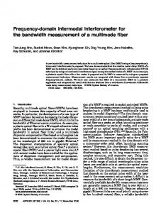
Fig. 2. Photograph of the spliced area showing the collapsed region at the end of the PCF fiber.
(8) We then find that Fig. 3. Schematic representation of the sensor.
(9) As shown in [9], during fusion the holes of the PCF acquire some ellipticity that gives rise to a parasitic birefringence causing polarization-dependent loss. This means that, as with PCF-based LPGs, -and -polarizations will be wavelength-shifted and the PDL is found as
and hence (15) Insertion into (13) yields for a given
(10)
(16)
B. Sensitivities be the total phase difference accumulated We let along the intermodal interferometer. When an external perturbation is imposed upon the sensing . For section, the phase difference changes by an amount of a core-cladding intermodal interferometer, the physical quantities that can lead to phase changes are: temperature , strain , pressure , and refractive index of the surrounding medium. For symmetrical deformation effects, within a first approximation, the resultant phase change can be written as [11] (11)
It follows then that (17) where is some cladding mode-order-dependent constant. If interference occurs between the fundamental core mode and more than one cladding mode, several spectral periodicities will be superimposed and the structure will exhibit a more complicated response. IV. EXPERIMENT
or also as (12) ( ) are the sensitivities and are the where phase change. quantities of each measurand that introduce a The smaller the , the greater the sensitivities . For a given length of sensing section (13) where is wavelength dependent constant which for highly birefringent fibers is proportional to [12]. The quantities are the periods of the cosine interferometric response for a given . As the lengths of the sensors can be measurand different, the sensitivities have to be normalized to unit length (1 m for example). Also, with spectral detection, the intermodal sensor has to be compared to LPG- or FBG-based sensors. To do this we note that (14)
A. Fabrication and Characterization We fabricated several samples of all-fiber SMF-PCF-SMF structures, establishing lengths of the PCF section from mm to mm. The sample having the PCF section mm was subjected to various tests. A photowith graphic image of the SMF-PCF joint is shown in Fig. 2, while the schematic drawing of the sensor is presented in Fig. 3. The spectral response of the intermodal sensor shown in Fig. 4(a) was taken using an ASE broadband source and an Ando AQ6315A OSA. Using (7) and the wavelength periods from Fig. 4 we can easily calculate the wavelength dependence of the intermodal dispersion and corresponding effective refractive index differences. The plot of the former is presented in Fig. 4(b). The average values for the intermodal dispersion and the effective refractive index and are ns km and . Looking at Fig. 4(a) we notice that the amplitude of the response is not constant. Small fluctuations in the periodicity are also noticeable. There are two major reasons for this observation.
Authorized licensed use limited to: Wojtek Bock. Downloaded on September 17, 2009 at 17:13 from IEEE Xplore. Restrictions apply.
3936
JOURNAL OF LIGHTWAVE TECHNOLOGY, VOL. 27, NO. 17, SEPTEMBER 1, 2009
Fig. 6. Response to elongation.
Fig. 4. (a) Spectral response of the obtained intermodal sensor. (b) Spectral dependence of the intermodal dispersion. Fig. 7. Response to hydrostatic pressure.
high, the PDL reaches levels as high as 10 dB which is more than typical PDL for either cascaded LPGs or LPGs based on the SMF-28. B. Measurement of Sensitivities to Strain, Hydrostatic Pressure, and External Refractive Index
Fig. 5. Spectral responses of the the intermodal interferometer.
- and
-polarized outputs and the PDL of
The first is the unwanted excitation of more than one higher order cladding mode which modulates the sine response interferometer. The problem can be overcome with more careful filtering of parasitic modes. The second is the existence of a polarization-dependence of the intermodal interference. This polarization sensitivity arises in the collapsed regions at the splices where the holes of the PCF fiber become elliptic in shape with random orientation, which, in turn causes random parasitic birefringence and PDL. Using an analyzer before the photodetector, we measured the responses for the - and -polarized outputs and calculated the corresponding total losses and the PDL whose spectral dependence is shown in Fig. 5. The PDL dependence is similar to that of cascaded LPGs forming a Mach–Zehnder type of interferometer such as the one studied here. Because the higher order cladding mode is lossy at the second splice and the parasitic birefringence is relatively
We measured the sensitivities to strain, hydrostatic pressure, temperature, and external refractive index changes using different samples. Fig. 3 shows the dimensions of the sensor arrangement for strain sensing. Because of the epoxy area covering the splices, mm. the active sensing length is reduced to We measured the wavelength shifts of the last minimum from Fig. 4(a) caused by elongation and the results are plotted in Fig. 6. As with LPGs, the sensitivity to strain has a negative coefficient, which means that the interference pattern moves left mm to lower wavelengths. For the sensing length of nm mm. the sensitivity was found to be The sensitivity to pressure was measured after we installed mm in a high-pressure another sensor with length chamber. The wavelength shifts versus pressure are shown in pm bar. Fig. 7 and the sensitivity was found to be Measurement of temperature response yielded a sensitivity of pm K. Since the higher order mode is a cladding mode of a glass-air waveguide, any change of the outer refractive index caused by immersion in a liquid will change the propagation constant of the higher order mode and consequently cause a shift in the interference fringes. Given that the sensors have to be inserted
Authorized licensed use limited to: Wojtek Bock. Downloaded on September 17, 2009 at 17:13 from IEEE Xplore. Restrictions apply.
BOCK et al.: INLINE CORE-CLADDING INTERMODAL INTERFEROMETER
Fig. 8. Spectral responses to immersion in water for two different sensing lengths.
3937
Fig. 9. Wavelength shifts of the intermodal sensor caused by SRI changes for two different sensing lengths.
TABLE II COMPARISON OF RESPONSES BETWEEN THE PRESENT LP -LP PCF-BASED INTERFEROMETER AND A PREVIOUS LP -LP SMF-BASED INTERMODAL INTERFEROMETER
Fig. 10. Visibility versus SRI changes for
in a liquid for pressure measurements, the sensitivity to refractive index for the transition air–water has been evaluated. Fig. 8 shows a comparison of the spectral responses in air and in water for an interferometer whose length mm. is The two responses in water correspond to the sensing lengths mm and (the parts immersed in water) of mm. For the 33-mm sensing length, the wavelength shift was nm per refractive index change of r.u.i. (refractive index units). Since the spectral period is nm, then using (14) we find that r.i.u. rad r.i.u. From and the corresponding sensitivity is product is obtained as 4.03 r.i.u. m. (15), the In the refractive index range from 1.33 to 1.38, r.i.u. ( rad r.i.u.) and in the range from 1.38 to r.i.u. ( rad r.i.u.) as summarized in 1.44, Table II. Thus, as with LPGs, sensitivity dramatically increases as the external refractive index approaches that of the cladding. Fig. 9 below shows the wavelength shifts caused by a change in the SRI for two different sensing lengths. The slopes of each section are the sensitivities given in Table II. Because the confinement and loss of the higher order cladding mode depends on the ambient refractive index, its relative part will change as the SRI changes. This will affect the visibility of the fringes given by (4). The dependence of versus SRI is shown in Fig. 10. It is clearly seen that as the SRI increases the visibility does not drop monotonically, but shows a periodic change before dropping considerably at refractive index values close to those of the cladding. It is worth comparing the present sensor with
mm.
TABLE III COMPARISON OF RESPONSES BETWEEN THE PRESENT LP -LP PCF-BASED INTERFEROMETER AND PCF -BASED TAPERED LPGS
conventional SMF-28-based LP -LP intermodal sensors as well as with PCF-based LPGs. Table II compares the present PCF-based core-cladding mode interference sensor and an earlier SMF-28-based core–core mode interference sensor. The sensitivity is expressed in terms product which is a constant quantity. We see that of the . this PCF intermodal sensor is about 40 times less sensitive to temperature (which is important for temperature compensation), 9.3 times less sensitive to strain, and about 5.8 times more sensitive to pressure. Table III compares the same PCF-based core-cladding mode interference sensor and a PCF-based tapered LPG reported in mm, while the [8]. The TLPG’s sensing length is lengths of the PCF core-cladding intermodal sensor vary between 33 and 45 mm as indicated in parentheses. This PCF-based TLPG pressure sensor [9] functions in reflective configuration, so that light passes twice along the same
Authorized licensed use limited to: Wojtek Bock. Downloaded on September 17, 2009 at 17:13 from IEEE Xplore. Restrictions apply.
3938
JOURNAL OF LIGHTWAVE TECHNOLOGY, VOL. 27, NO. 17, SEPTEMBER 1, 2009
The results are presented in Fig. 11 from which we note that 8 nm mm which means of 15 points lie on a line with that for those samples there is an interference between the core mode and only one cladding mode. The rest of the points show a deviation from this value, which we regard as due to the existence of more than one cladding mode. Fig. 11(a) shows a plot of versus and a curve fitting for nm mm. Fig. 11(a) and (b) reveal the fact that only about 50% of the splices produced a repeatable excitation of the higher order interfering mode. Hence, improvement in fabrication technology, though simple in itself, is of key importance for the proper functioning of the core-cladding intermodal interferometer. V. CONCLUSION
Fig. 11. Length dependence of (a) the periodicity, and (b) of experimentally products. measured
LPG. The TLPG length being 20 mm, the effective sensing mm with a reported sensitivity to length then becomes pm bar. For the same sensing length, pressure the LP -LP intermodal PCF-based sensor shows a sensitivity pm bar which is an increase by 50% at a of temperature sensitivity of less than 3 pm/K. Sensitivity to strain is negative and about 2.1 times smaller than that of the PCF TLPG sensor. Compared to LPGs, sensitivity to refractive index changes is lower but covers a wider range. Thus with the intermodal interferometer we obtain practically constant sensitivity to , versus almost 10 times as of 700 nm/r.i.u. for to [7]. much for the range from The two comparisons show that the type of sensor discussed here is best suited for temperature-insensitive pressure, strain, and refractive index sensing. One disadvantage is the higher splice losses which is common for this type of sensors. Progress is underway to seriously minimize them. On the positive side, the major advantage over the LPGs is that the sensitivity can be increased by increasing the sensing length. In this case, maxima will be closer to one another and wavelength shifts can be measured with greater accuracy. As noted above, a departure from the ideal cosine response was observed on several occasions and two possible causes were outlined: polarization dependence and the presence of more than one cladding mode suggesting that at least two independent responses are superimposed. To test the latter assumption we in (17) is mode-order dependent. We note that the constant for samples then measure the averaged periods ranging from 5 to 152 mm and calculate the value of with which will be independent of if there is interference with only one higher order cladding mode.
We have fabricated and tested a simple and cost-effective core-cladding mode interferometer based on an endlessly single-mode PCF fiber spliced between a lead-in and a lead-out standard SMF-28 fiber. The interferometer is sensitive to pressure, strain and ambient refractive index changes as well as bending. It shows a sensitivity to pressure five times higher than that of a core–core intermodal sensor based on SMF-28 fiber and 50% higher than that of a tapered PCF-based LPG. As the sensing fiber is a photonic crystal one, temperature sensitivity is very low. The PDL of the sensor was found to be about 10 dB, which is higher than for SMF-28-based LPGs, and is due to the higher parasitic birefringence at the splices. This type of sensor features the typical advantages of PCF-based LPGs. Its sensitivity can be augmented by increasing the sensor length.
REFERENCES [1] V. P. Minkovich, D. Monzón-Hernández, J. Villatoro, and G. Badenes, “Microstructured optical fiber coated with thin films for gas and chemical sensing,” Opt. Exp., vol. 14, pp. 8413–8418, 2006. [2] J. Villatoro, V. P. Minkovich, V. Pruneri, and G. Badenes, “Simple allmicrostructure optical-fiber interferometer built via fusion splicing,” Opt. Exp., vol. 15, pp. 1491–1496, 2007. [3] J. Villatoro, V. Finazzi, V. P. Minkovich, V. Pruneri, and G. Badenes, “Temperature-insensitive photonic crystal fiber interferometer for absolute strain sensing,” Appl. Phys. Lett., vol. 91, 2007, 091109. [4] H. Y. Choi, M. J. Kim, and B. H. Lee, “All fiber Mach–Zender type interferometers formed in photonic crystal fiber,” Opt. Exp., vol. 15, pp. 5711–5720, 2007. [5] T. A. Eftimov and W. J. Bock, “Sensing with a LP -LP intermodal interferometer,” J. Lightw. Technol., vol. 11, no. 12, pp. 2150–2156, Dec. 1993. [6] D. Káˇcik, I. Turek, I. Martinˇcek, J. Canning, N. Issa, and K. Lyytikäinen, “Intermodal interference in photonic crystal fiber,” Opt. Exp., vol. 12, pp. 3465–3470, 2004. [7] V. Bhatia, “Applications of long-period gratings to single- and multiparameter sensing,” Opt. Exp., vol. 27, pp. 457–466, 1999. [8] S. Lacroix, R. Bourbonnais, F. Gonthier, and J. Bures, “Tapered monomode optical fibers: Understanding large power transfer,” Appl. Opt., vol. 25, pp. 4421–4425, 1986. [9] W. J. Bock, J. Chen, P. Mikulic, and M. Pawlowski, “Pressure sensing using long-period tapered gratings written in photonic crystal fibers,” in Proc. OFS-18, Cancun, Mexico, Oct. 2006, paper ThA6. [10] T. A. Eftimov, W. J. Bock, J. Chen, and P. Mikulic, “Müller–Stokes analysis of long-period gratings. Part I: Uniformly birefringent LPGs,” J. Lightw. Technol., to be published. [11] T. R. Wolinski, “Polarimetric optical fibers and sensors,” in Progress in Optics, E. Wolf, Ed. Amsterdam, The Netherlands: North Holland, 2000, vol. XL, pp. 1–75. [12] W. J. Bock and T. R. Wolinski, “Temperature-compensated strain sensor based on polarization-rotated reflection,” in Fiber Optic Smart Structures and Skins III. Philadelphia, PA: SPIE, 1990, vol. 1370, Proc. SPIE, pp. 189–196.
Authorized licensed use limited to: Wojtek Bock. Downloaded on September 17, 2009 at 17:13 from IEEE Xplore. Restrictions apply.
BOCK et al.: INLINE CORE-CLADDING INTERMODAL INTERFEROMETER
Wojtek J. Bock (F’01) received the M.Sc. degree in electrical engineering and the Ph.D. degree in solid state physics from the Warsaw University of Technology, Warsaw, Poland, in 1971 and 1980, respectively. He is currently a Full Professor of Electrical Engineering and Canada Research Chair in Photonics at the Université du Québec en Outaouais, Quebec, QC, Canada. He is also Director of the Photonics Research Center at this University. His research interests include fiber optic sensors and devices, multisensor systems, and precise measurement systems of nonelectric quantities. He has authored and coauthored more than 240 scientific papers, patents, and conference papers in the fields of fiber optics and metrology. Dr. Bock was a member of the Administrative Committee of the IEEE Instrumentation and Measurement Society. In May 1997, he was General Chairman of the IMTC/97 in Ottawa, ON, Canada.
3939
Predrag Mikulic received the A.S. degree in telecommunication engineering technology from the University of Sarajevo, Sarajevo, Yugoslavia, in 1989. He is currently with the Photonics Research Center, University of Quebec, Quebec, QC, Canada. His major interests are thin film depositions, excimer lasers, photonic devices, fiber sensors, and splicing recipes of dissimilar fibers including photonic crystal fibers.
Jiahua Chen graduated from Precision Instrument Department, Tsinghua University, Beijing, China, in 1970. He is currently with the Centre de Recherche en Photonique, Département d’Informatique et d’Ingénierie, Université du Québec en Outaouais, Québec, QC, Canada. His interests include optical fibers, polarization phenomena, fiber gratings, and optical fiber pressure sensors.
Tinko A. Eftimov received the M.Sc. in quantum electronics from Sofia University, Sofia, Bulgaria, in 1982 and the Ph.D. in applied physics from the Technical University, Sofia, in 1989. He is currently with the Department of Experimental Physics, Plovdiv University, Plovdiv, Bulgaria. His interests include optical fibers, polarization phenomena, intermodal interference, fiber gratings, and fiber optic sensors. In these fields he has authored and coauthored more than 60 journal and conference papers.
Authorized licensed use limited to: Wojtek Bock. Downloaded on September 17, 2009 at 17:13 from IEEE Xplore. Restrictions apply.