An innovative low-cost Classification Scheme for combined multi-Gigabit IP and Ethernet Networks Ioannis Papaefstathiou
Vassilis Papaefstathiou
Inst. of Computer Science (ICS), Foundation for Research & Technology - Hellas (FORTH) – Member of HiPEAC Vassilika Vouton, P.O. Box 1385, Heraklion, Crete, GR-711-10, Greece
[email protected]
Inst. of Computer Science (ICS), Foundation for Research & Technology - Hellas (FORTH) – Member of HiPEAC Vassilika Vouton, P.O. Box 1385, Heraklion, Crete, GR-711-10, Greece
[email protected] and the associated equipments, is their low cost, the classification solutions that would be used within the specified frameworks should be as cost efficient as possible. In the case of IP classification, longest prefix match of the 32-bit IP address is needed which is certainly a complicated task.
Abstract— IP is certainly the most popular wide area network protocol while Ethernet is the most common Layer-2 network protocol, and it is currently being deployed beyond the tight borders of LANs. In order to accommodate the needs of MANs and WANs, several QoS mechanisms employed either at the IP layer or the MAC sublayer have been proposed. These QoS mechanisms require identification of network flows and the classification of network packets according to certain packet header fields. In this paper, we propose a classification engine employed either at the MAC sublayer or the IP layer, which is the successor of a scheme already successfuly implemented which is only employed at the MAC sublayer. This new scheme uses an innovative hashing scheme combined with an efficient trie-based structure. By using such techniques, the extremely high speed decisions –at a rate of more than 100Gb/sec- are supported, while the memory needs of the proposed engine are significantly lower compared to those of the similar schemes currently used. This engine has been implemented in hardware utilizing less than 0.2mm² in a state of the art CMOS technology. As a result the proposed scheme is a very promising candidate for both the nextgeneration IP classification engines(probably incorporated within the high-end network processors) as well as for the Ethernet equipments that need to support classification at multi-Gigabit per second network speeds, while also employing the minimum amount of memory.
I.
In this paper, we propose a classification engine utilized both at the MAC sublayer and at the IP layer which uses a new hashing scheme and internal replacement of MAC Vendor IDs at the Ethernet layer, and the same hashing scheme together with an innovative trie-based engine for the IP classificaton; the Double Layer Classification Engine (DLCE) can reach classification decisions at extremely high speeds while its main advantage is that it utilizes less than two thirds of the memory needed by the existing solutions. The efficiency of the proposed engine comes from the fact that the hashing and the replacement schemes, together with the trie-based engine used, take advantage of the individual characteristics of the MAC and IP addresses, respectively. This engine is the successor of the HBCE hardware module, presented in [3] which is only capable of supporting Layer-2 network packets. DLCE has also been implemented in hardware and while its implementation cost is minimal, it supports network rates higher than 100 Gb/sec while incorporating 128K independent rules. II.
INTRODUCTION
RELATED WORK
L2 classification requires the fields mentioned in the last section to be examined and the appropriate action to be performed. Therefore, the network equipments need to store some information and consult them for their decisions. The information regarding the MAC or IP addresses, the VLANs and the Ports are stored in internal data structures and for each packet a search is conducted using the corresponding packet header fields.
Ethernet is, by far, the most common Layer-2 network protocol, and it is currently exploited in MANs and WANs. Therefore, there are several schemes proposed for the QoS support at this layer, such as the VLAN scheme employed in the MAC sublayer [1], or certain QoS protocols for wireless environments [2]. At the same time an Internet router which provides more advanced services than packet forwarding, must today support fine grained QoS. Those QoS mechanisms require identification of network flows and classification of packets according to their MAC or IP addresses, VLAN IDs and port number fields. Moreover, in order to be able to support fine-grained QoS they incorporate tens of thousands of independent network flows identified by those fields. In the case of Ethernet classification the length of the MAC addresses, namely 48-bits, is what makes the classification task difficult since exact matches in such a wide value is not a trivial task. Since the main advantage of the Ethernet networks,
The nature of L2 classification requires exact matches and many implementations use CAMs that provide single access matching [4]. CAM solutions, although simple, they are expensive and consume large amounts of power. Trie based solutions [5] have poor performance since they cannot handle efficiently long matching strings such as the MAC address. Moreover, trie based solutions, at the MAC layer may require several memory accesses and massive storage for the associated pointers.
211 1-4244-0355-3/06/$20.00 (c) 2006 IEEE This full text paper was peer reviewed at the direction of IEEE Communications Society subject matter experts for publication in the IEEE ICC 2006 proceedings.
MAC_TBL and the indexes to it are generated by our hashing function applied to the address bits. The collisions due to hashing are handled by pointers to variable size blocks. Handling variable size blocks requires a dynamic memory management scheme which is described in [3]. The number of entries in each variable size block is defined by the number of rules that collide within a specific entry of the EXACT_TBL.
Another popular solution is hashing of the MAC address bits and storing the data in SRAM based lookup tables. The 48bits are hashed using a specific hashing function and an index for the lookup table is generated. Many solutions use the CRC polynomials for hashing since they have been proved very efficient [6] however others, mainly due to cost reasons, use direct mapping by the least significant bits of the MAC address [7].
In the most challenging task of the 48-bit MAC addresses our hashing scheme applies an XOR function and the 16-bit EXACT_TBL address is produced as follows:
For the IP classification tasks the numerous longest prefix matches (LPM) algorithms proposed for IP routing are in general employed. One class of those schemes uses CAMs such as [4], while several others make extended use of tries and traverse tree data structures to find the matching prefix, as presented in [5]. Unibit tries check one bit at a time and follow the nodes until no matching bit is found. Schemes of this type have a worst case lookup of 32 memory accesses for IPv4 (since the IPv4 address fields are 32 bits long) and spend also lot of memory to save the pointers for the next nodes. On the other hand, multi-bit tries traverse several bits at a time and this provides faster searches. For example if we check 4 bits at a time (4-bit strides) then the worst case is 8 memory accesses. In these tries, problems arise when the prefixes are not multiples of the stride length. Solution to this problem is prefix expansion as described in [8]. CPE generates many prefixes and leads to great memory waste (especially when the stride length grows) and to non deterministic update times.
EXACT_TBLindex = {MAC[47:40] xor MAC[31:24] xor MAC[15:8], MAC[39:32] xor MAC[23:16] xor MAC[7:0]} To identify a certain MAC-address rule within a particular table entry we also need to save some additional information so as to be able to distinguish those that collide. Fortunately, we don’t need to save all 48-bits and we take advantage of the fact that the XOR function can be “inversed”. Therefore a certain MAC-value associated with address A of MAC_TBL can be reproduced by the 16-bits of A and the last 32-bits (Hval) of the MAC address as follows: MAC[47:40] = A[15:8] xor Hval[31:24] xor Hval[15:8] MAC[39:32] = A[7:0] xor Hval[23:16] xor Hval[7:0] MAC[31:0] = Hval(31:0) So by using Hval we can uniquely identify each MACaddress rule. If we use CRC-16 to produce the 16-bit indexes, like the popular schemes described in the related work section, then we would have to store the complete 48-bits of the MAC address since there is no inverse CRC function. Moreover, CRC polynomials don’t have one-to-one correspondence between input and generated values. The speed and storage performance of our hashing function is discussed in section IV.
Other, LPM schemes from literature like Lulea [9] tried to solve the memory waste of CPE by using compressed bitmaps to represent strides. They use strides of 16,8 and 8-bits consecutively to represent the 32-bit IPv4 address space. The first 16bits are used as an index to a 64K table and the next 8bit strides are represented by their own bitmap algorithm where each stride requires 32 bytes nodes even if only 1 prefix exists in the 256 space. A lookup is performed at worst case with 9 memory accesses but incremental updates to this scheme are inherently slow. Lulea is the most storage efficient scheme presented in literature so far. III.
B. MAC Vendor Replacement The official IEEE OUI [10] has published all the assigned 24-bit MAC vendor IDs and the associated company names. Based on them we have observed that the 24-bit vendor address space of the MAC addresses is not fully occupied. In fact, fewer than 8000 vendors are active instead of the 224 possible. Therefore we can replace the 24-bit vendor ID with a 13-bit internally assigned vendor ID. The last 24-bits of the MAC address that uniquely identify a device, of a certain vendor, remain unchanged. This replacement reduces the storage requirements for each MAC-address rule, at the cost obviously of the replacement operation. Consequently, every incoming MAC-address rule need to be translated before the actual processing begins.
DOUBLE LAYER CLASSIFICATION ENGINE
Our solution for both Layer-2 and Layer-3 classification is based on hashing, but we propose a scheme that exactly matches the special characteristics of the MAC and IP addresses. Moreover, in the MAC sublayer it employs the technique of internal MAC Vendor replacement, while in the IP layer it uses a sophisticated trie-based algorithm. The DLCE is designed to support tens-of-thousands of IP and MACaddress rules. Every rule in the ruleset is associated to a number called FlowID (which can, for example, be a pointer to another memory which holds the associated information for this rule or simply a number identifying the output port of the device). We decided to use 15-bit FlowIDs, translating to 32K unique and independent network flows, which have been proved to be enough for most network equipments.
We can now consider that each MAC-address rule handled by our system is 37-bits long. Naturally, this replacement means that we keep a small table with 8192 entries called VID_RPL that matches the existing 24-bit Vendor ID values with the internally assigned 13-bit Vendor ID values. This table can be easily constructed since all Vendor IDs are sequentially assigned by IEEE and a few ‘holes’ that exist in the address space can be handled by a 24-to-13 decoder. Although this
A. MAC Address Hashing We developed a hashing function to map the IP and MACaddress rules into a table that will hold the FlowID of the associated rule. Those rules are stored in a 64K table called
212 This full text paper was peer reviewed at the direction of IEEE Communications Society subject matter experts for publication in the IEEE ICC 2006 proceedings.
table is constant and thus can be kept in a ROM, we can also use a method that learns the connected MAC addresses and assigns incrementally an internal Vendor ID.
•
The updates in the nodes are executed by well defined routines and in deterministic time.
After this replacement we define a new hashing function on the 37-bits of the MAC address. Now, the 16-bit indexes in MAC_TBL are generated as follows: MAC_TBLindex = { MAC[31:24] xor MAC[15:8] , MAC[23:16] xor MAC[7:0] } Notice that we don’t use the 6 MSB of the replaced Vendor ID in order to have a byte balanced hashing function. The new Hval is now 21-bits and is defined as follows: Hval = { MAC[36:24] , MAC[7:0] } Now, a MAC-address associated with address A of MAC_TBL can be reproduced by the 16-bits of the address and Hval as follows:
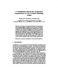
Figure 1. Routing Table Distribution
1) DLCE Trie Nodes The key data structure of DLCE is a trie node that can hold prefixes of lengths from 0 to 7 bits. This trie has 8 levels and therefore the total number of possible prefixes that can be accommodated are 255. We can use a bitmap to represent all the possible prefixes and this needs at least 255 bits as presented in [9]. According to this representation every prefix is correlated with a specific bit position inside the bitmap. If a specific bit is set then the corresponding prefix exists.
MAC[36:24] = Hval[20:8] MAC[23:16] = A[7:0] xor Hval[7:0] MAC[15:8] = A[15:8] xor Hval[15:8] MAC[7:0] = Hval(7:0) As described in [3], the FlowID, the Hval and the information containing the number of collisions and the address of the first of the chain of the collided nodes are all fitted in a 36-bit standard memory word.
Consider a trie that can accommodate prefixes with lengths from 0 to 3 bits as shown in Fig. 2. The prefix with length 0, namely *, is assigned with number 0, the prefix with length 1 and the prefix bit set to 0, namely 0*, is assigned with number 1, the prefix with length 1 and the prefix bit set to 1, namely 1*, is assigned with number 2 and so on as Fig. 2 presents. Moreover, the level of the trie where a specific prefix is located is equal to its length.
C. IP layer classification In order to be able to develop an efficient classification scheme, we collected several routing tables from backbone routers of the Internet that are available in IPMA [11] and analyze them, in terms of the length of the various prefixes. Note that those routing prefixes are also used for the classification of the network flows according to the different QoS criteria. The distribution of the various lengths is shown in Fig. 1; from this graph it is clear that 99% of the prefixes have lengths in the interval between 16 and 24 and more than half of the total prefixes have length equal to 24. This distribution has been found to be constant over time and stable between routing tables of various sizes, hence we have used as a basis for our algorithm. In particular the proposed scheme has the following properties: 1. 2. 3. 4. 5.
Easily implementable in hardware Moderate algorithmic complexity Fast lookups times for common case Lower storage requirements than the existing solutions Deterministic and bounded incremental update times, in comparison with the unbounded such times of the vast majority of the proposed schemes In order to cope with the above requirements we ended up with the DLCE which: • Uses strides and multi-bit trie nodes in order to traverse several bits at a time and produce fast lookups. • Employs data structures with multi-bit nodes optimized to perform efficiently in the prefix interval 16 to 24. • Its nodes are represented with bitmaps that can be processed fast in hardware and require small storage.
Figure 2. Prefix trie that supports prefixes up to length 3
We can derive a formula that correlates the length and the decimal value of a prefix with a number. Prefix with length 0 is assigned number 0 and all the other prefixes are numbered by the following formula: PrefixNO = PrefixValue + 2PrefixLength – 1 The assigned prefix number can be used to indicate a specific bit position inside the bitmap. Since the bitmap that can accommodate all prefix lengths from 0 to 7 needs 255 bits even for a single prefix in this range, the trie node needs 32 bytes. We can prevent this memory waste and partition this trie
213 This full text paper was peer reviewed at the direction of IEEE Communications Society subject matter experts for publication in the IEEE ICC 2006 proceedings.
To locate the subtrie of a specific prefix in the trie bitmap we use the subtrie formula below, where Tindex indicates the bit position of the actual subtrie number.
in 17 subtries where each subtrie can support prefixes with lengths 0 to 3 as shown in Fig. 3. We store the prefixes that have length 0 to 3 in the subtrie numbered 0 and the prefixes of higher length, namely 4 to 7, to the corresponding subtrie. The subtrie for the prefixes that have length 4 to 7 is defined by the 4 MSB of the prefix. The prefixes that have their 4 MSB equal to 0000 are stored in the subtrie numbered 1, the prefixes that have their 4MSB equal to 0001 are stored in the subtrie numbered 2 and so on as Fig. 3 presents.
• •
If the Tindex = If the Tindex =
prefix has length 0-3 then : 0 prefix has length 4-7 then : prefix[0:3] + 1
To locate a specific prefix in the prefix bitmap we present the formula shown below, where Pindex indicates the bit position of the actual prefix in a specific subtrie. •
Figure 3. Trie partitions
•
We can easily derive a formula that correlates the length and the MSB of a prefix with a subtrie number. Prefixes with length 0 to 3 are stored in the subtrie 0 and for the prefixes of lengths from 4 to 7 we use the following formula to find the subtrie number: SubtrieNO = PrefixValue[0:3] + 1 To store efficiently the information about the subtries, in the DLCE we define a certain bitmap call TrieBmp. In TrieBmp we correlate each bit with a specific subtrie according to the SubtrieNO formula. When a bit inside TrieBmp is set then the corresponding subtrie has a least 1 prefix active. For every active subtrie we need the information about the active prefixes belonging to it, therefore we define another bitmap called PrefixBmp. In PrefixBmp we correlate each bit with a specific prefix according to the PrefixNO formula. When a bit inside PrefixBmp is set then the corresponding prefix is included in the overall data structure (i.e. the prefix is “active”).
If Tindex = 0 • If prefix length is equal Pindex = 0 • If prefix length is equal Pindex = prefix[0] + 1 • If prefix length is equal Pindex = prefix[0:1] + 3 • If prefix length is equal Pindex = prefix[0:2] + 7 If Tindex != 0 • If prefix length is equal Pindex = 0 • If prefix length is equal Pindex = prefix[4] + 1 • If prefix length is equal Pindex = prefix[4:5] + 3 • If prefix length is equal Pindex = prefix[4:6] + 7
to 0 then : to 1 then : to 2 then : to 3 then :
to 0 then : to 1 then : to 2 then : to 3 then :
To illustrate the data structures used by DLCE we introduce an example with the prefixes shown in Table I. The two leftmost columns have the actual prefixes and the associated information and the two rightmost columns show the internally represented subtrie and prefix number pairs. As calculated, a general view of the data structure needed to store the prefixes of the example is shown in Fig. 4. TABLE I.
Prefix [0:6] 00001* 0000101* 0000110* 01* 100* 1001* 1100* 110011*
The partitioning of 8-bit tries into smaller 4-bit subtries gives the flexibility to save only the active prefix bitmaps and not all of them. The trie bitmap needs 17 bits and each prefix bitmap needs 15 bits. This partitioning can be efficiently implemented by the dynamic memory management scheme of the MAC classification engine presented in detail in [3], because the variable number of prefix bitmaps requires pointers to variable size blocks. The associated information for each prefix is considered an N-bit quantity (the data associated with each rule), say 16-bits, and should be stored along with the prefix bitmap. Since more than one prefixes could be active we also need dynamic pointers to variable size blocks. So along with the prefix bitmap we save a pointer to the associated prefix data.
PREFIX EXAMPLE
Associated Info 23 47 7 15 121 36 51 3
Subtrie Number 1 1 1 0 0 10 13 13
Prefix Number 2 12 13 5 11 0 0 6
In order to be able to efficiently search the blocks that are generated by our dynamic memory management scheme described in detail in [3] we have to have the prefix bitmaps and the associated prefix information sorted inside the blocks. The prefix bitmap for the first active subtrie should be placed first in the variable size block, the second in the second position etc. Moreover this indicates that we should know the number of set bits in the bitmap, fortunately this is a trivial
214 This full text paper was peer reviewed at the direction of IEEE Communications Society subject matter experts for publication in the IEEE ICC 2006 proceedings.
operation for hardware to perform. The requirement for dynamic memory management generates an additional complexity in insertions or updates since the variable size blocks need to be resized appropriately and put sorted. This operation can be handled easily since resizing and sorting is limited to 17 nodes.
possible roots, therefore we use a 256-entry table called TBL8 and the indexing is done with the first 8-bits of the prefix. For interval 16-23 we use a 216=65536 table called TBL16 and uses the first 16-bits of the prefix as index. For interval 24-31 we don’t use 224 entries because it would lead to great storage waste since no routing table could have 16777216 prefixes in this interval. Instead we use 216 entries in table TBL24 and indexing is done by hashing the first 24-bits of the value. For the 32 bit prefixes we use only 212 entries in table TBL32, since most routing tables have few entries in this interval, and addressing is done by hashing.
Figure 4. Trie data structure example
For a given 7-bit value, DLCE should first find the candidate subtries that could match a certain prefix and then the candidate prefixes, inside the subtrie, that could also match. Tracking the longest subtrie is the solution. The candidate subtries are always two:
Figure 5. DLCE Tables
Indexes in TBL24 and TBL32 are generated by the exact same function as in the case of MAC Layer classification by using the corresponding bits, while the collisions are also handled by the same scheme handling the collisions in Layer-2 and described in section III.A.
T1index= 0 and One of the subtries 1-16 depending on the value T2index = value[0:3] + 1.
Inside the two subtries the candidate prefixes are four:
for T1index : P1index = 0 P2index = value[0] + P3index = value[0:1] P4index = value[0:2] for T2index : P1index = 0 P2index = value[4] + P3index = value[4:5] P4index = value[4:6]
Note that all distinct intervals are independent and this gives us the flexibility to start searching for a prefix from the middle of the address space. Searching sequentially would require to lookup all 5 tables but we can use a binary search type of access and limit the lookups to 3 or less. Furthermore, we can implement parallel searches in hardware if each table is stored in a separate memory.
1 + 3 + 7
1 + 3 + 7
The DLCE searches the tables in specific sequence in order to minimize the number of accesses. Since 99% of the prefixes exist in the intervals 16-23 and 24-31, it is more likely to find the longest match there by examining the associated tables. At first we look in TBL16 and if a prefix match occurs then we can search in TBL24 and TBL32 to find a matching prefix. If lookups in TBL16 or TBL24 or TBL32 cannot find a match then we proceed to search TBL8 and if there is not any match again we finally search in TBL0. If after TBL32 a match was produced then our lookup process does not proceed to the next tables. The sequence of lookups is the following:
We check the bit positions in TrieBmp for the two subtries and if both exist we give priority to the second subtrie which produces longer prefixes. Inside a matching subtrie we check all the bit positions in PrefixBmp for the 4 prefixes by giving priority to the fourth prefix which is the longest. The associated information for a matched prefix is retrieved by the node indicated by the pointer stored at the node of the matched prefix. The DLCE scheme uses the trie nodes for all the distinct 7bit prefix lengths inside the 32-bit address space. In particular, it supports trie nodes for the following prefix intervals: (a) 0-7, (b) 8-15, (c) 16-23, (d) 24-31 and (e) 32. To hold the root nodes for the prefixes in each distinct interval, DLCE uses several tables as shown in Fig. 5. For the interval 0-7 we have a single entry for root called TBL0. For interval 8-15 we have 28
TBL16 → TBL24 → TBL32 → TBL8 → TBL0 IV.
PERFORMANCE AND HARDWARE COST
In this section we calculate and analyze the storage needs of DLCE, while we also present the performance achieved by our hardware implementation, together with its complexity. In the case of Layer-2 classification, as it is clearly demonstrated in
215 This full text paper was peer reviewed at the direction of IEEE Communications Society subject matter experts for publication in the IEEE ICC 2006 proceedings.
As those results clearly demonstrate the proposed scheme can be a very valuable component/submodule not only for the Layer-2 network equipments, but, more importantly, for today’s multi-layer network processing units that need to support QoS for several thousands network flows at the network rate of 100Gb/sec.
[3], the memory requirenments are significantly lower than those of the existing solutions (mainly the ones based on the CRC function), while the proposed scheme is also simpler and less expensive to implement in hardware than the corresponding CRC one. For the IP classification, we demonstrate in Table II both the memory needed for the static tables, as well as the memory requirements of the scheme when the entire real-world prefix tables are stored in its data structures. TABLE II. Prefix Table (Total Prefixes) AADS (40K) MAE-EAST (60K) PAIX (90K)
TABLE III. Active MAC Addresses 32K 48K 64K
MEMORY REQUIREMENTS FOR IP CLASSIFICATION Static Tables
Collision Nodes
Trie Nodes
Total
595 KB
24 KB
236 KB
855 KB
595 KB
59 KB
357 KB
1011 KB
595 KB
128 KB
538 KB
1264 KB
IP-layer
DLCE NETWORK PERFORMANCE
SRAM 200MHz Average Worst Case (Gbps) (Gbps) 17.1 68.7 14.6 59.2 12.8 51.7 16.2
52.1
SRAM 400MHz Average Worst Case (Gbps) (Gbps) 34.2 137.5 29.2 118.4 25.6 103.5 104.6
32.3
When comparing this scheme with the existing solutions,, in terms of Layer-2 classification, it has significnatly lower memory requirements than the existing solutions, while supporting, at least, the same decision rate. Moreover, when compared to the existing classification schemes, eventhough it needs slightly more memory than one of them, it is one of the very few that supports updates in bounded, and limited time, while it matches the performance of them in terms of the supporting network rates.
Those results clearly demonstrate that the static tables consume nearly 50% percent of the total storage. The collision nodes required are relatively small and require few Kbytes but the trie nodes possess a respectable part of the overall storage. The whole design is fully pipelined and uses four parallel memories/banks of memories, and thus the lookup performance of DLCE is based on the pipeline stalls which directly depend on the total number of memory accesses required to find a match. In the case of both Layer-2 and IP classification the performance of DLCE depends on the collisions on the main static tables, since when collisions occur we have to lookup sequentially all the colliding rules, triggering stalls in the pipeline. Moreover, in the case of the IP classification the performance also depends on the number of steps required to find the longest prefix match.
V.
CONCLUSIONS
This paper presents a novel classification engine that handles both Ethernet and IP network streams. The combined scheme called Double Layer Classification Engine (DLCE) handles up to tens of thousands distinct classification rules while supporting network rates even more than 100Gb/sec. The systems is the successor of the HBCE engine which could support only Ethernet packets. Its hardware implementation covers 0.18mm² of silicon area, while it is clocked at 300MHz.
To calculate the network performance we have used two different memory modules, 200MHz and 400MHz synchronous SRAMs. Since classification is performed for every incoming network packet, we calculate the throughput of our system based on the most conservative (worst-case) approach, by assuming that DLCE handles only minimum sized Ethernet (64 bytes) and IP (40-bytes) packets, while in the average case average packet sizes are considered. The summary of the supported link speeds is presented in Table III where the average throughput is based on the average pipeline stalls and the worst-case on the worst case stalls. This worst case is triggered when the lookups that should be performed, always encounter the maximum number of collisions and distinct number of steps in the case of IP classification.
REFERENCES [1] [2]
IEEE 802.1q Standard, “Virtual Bridged Local Area Networks”, Giovanni Pau et.al , “A Cross-Layer Framework for Wireless LAN QoS Support”, IEEE ITRE, August 11-13, 2003, Newark, New Jersey, USA [3] V. Papaefstathiou, I. Papaefstathiou, “A Hardware Engine for Layer-2 classification in low-storage, ultra-high bandwidth environments”, IEEE Design Automation & Test in Europe (DATE 2006), March 6-10, Munich, Germany.. [4] J. McAulay and P. Francis, “Fast Routing Table Lookup Using CAMs”, in IEEE Infocom, 1993. [5] P. Gupta and N. McKeown, "Algorithms for Packet Classification", IEEE Network, March/April 2001, vol. 15, no. 2, pp 24-32. [6] R. Jain, "A Comparison of Hashing Schemes for Address Lookup in Computer Networks", IEEE Transactions on Communications, Vol. 40, No. 3, Oct. 1992, pp. 1570-1573 [7] VIA Networking Atlantic™ VT6510A Switch Controller [8] V. Srinivasan and G. Varghese, “Faster IP Lookups using Controlled Prefix Expansion”, in IEEE Sigmetrics, 1998. [9] M. Degermark, A. Brodnik, S. Carlsson, and S. Pink, “Small Forwarding Tables for Fast Routing Lookups”, in ACM SIGCOMM, 1997 [10] IEEE OUI and Company_id Assignments, http://standards.ieee.org/regauth/oui/index.shtml [11] Internet Performance Measurement and Analysis (IPMA) project, http://www.merit.edu/~ipma/
This scheme has also been synthesized and placed and routed in a 0.13µm CMOS technology, and it covers only 0.18mm² of silicon area, while been clocked at 300MHz. In general, this new proposed system has all the advantages of HBCE, while it also supports classification decisions at Layer-3, at a minimal cost of an additional 0.8mm² of silicon, since 90% of the HBCE sub-module is also used by the IP classification engine.
216 This full text paper was peer reviewed at the direction of IEEE Communications Society subject matter experts for publication in the IEEE ICC 2006 proceedings.