An Instruction Scheduling Algorithm Based on Subgraph Isomorphism Ricardo Santos1 , Rodolfo Azevedo2 , Guido Araujo2 1
Computer and Engineering Research Group – Dom Bosco Catholic University (UCDB) Campo Grande – MS – Brazil 2
Institute of Computing – State University of Camnpinas (UNICAMP) Campinas – SP – Brazil
[email protected], {rodolfo,guido}@ic.unicamp.br
Abstract. This paper presents an instruction scheduling algorithm based on the Subgraph Isomorphism Problem. Given a Directed Acyclic Graph (DAG) G1 , our algorithm looks for a subgraph G02 in a base graph G2 , such that G02 is isomorphic to G1 . The base graph G2 represents the arrangement of the processing elements of a high performance computer architecture named 2D-VLIW and G02 is the set of those processing elements required to execute operations in G1 . We have compared this algorithm with a greedy list scheduling strategy using programs of the SPEC and MediaBench suites. In our experiments, the average Operation Per Cycle (OPC) and Operations Per Instruction (OPI) achieved by our algorithm are 1.45 and 1.40 times better than the OPC and OPI obtained by the list scheduling algorithm.
1. Introduction It is well-known that current high performance microprocessor architectures use hardware and software techniques to exploit the Instruction Level Parallelism (ILP) available in the applications. The proper scheduling of operations onto the hardware resources plays an important role in the final application performance. For architectures that schedule instructions at compile time, advanced compiler optimizations are essential to exploit the ILP available in programs. Advanced compiler optimizations, including new instruction scheduling strategies, can look at large code regions to find out larger parallelism levels [Faraboschi et al. 2001]. In order to adopt large code regions at scheduling time, there is an increasing number of scheduling techniques based on graph matching [Maheswaran and Siegel 1998]. These proposals range from scheduling operations on multiprocessor systems, clustered VLIW architectures, and heterogeneous computing systems. In this paper we address the instruction scheduling problem in a high performance computer architecture through a subgraph isomorphism approach. Instead of looking at single operations of a Directed Acyclic Graph (DAG) and allocating them to the hardware resources, our scheduling approach deals with two graphs: a DAG and a hardware resource graph. The goal is to match the DAG onto the hardware graph. This approach has shown to be very useful for architectures based on multiple processing elements once it easily captures the interconnection patterns of the DAGs and the available hardware
resources at scheduling time. We propose a new instruction scheduling algorithm for a multiple functional-unit architecture named 2D-VLIW [ommited for blind review ]. This architecture relies thoroughly on the compiler optimizations to provide speedup for the applications, since the compiler is the responsible for allocating and managing the hardware resources. We have performed some experiments considering the Operations Per Cycle (OPC) and Operations Per Instruction (OPI) obtained by our algorithm. We compare the results of the subgraph isomorphism scheduling with a greedy list scheduling algorithm using programs of the SPEC (integer and float-point) [Henning 2000] and MediaBench [Lee et al. 1997] suites. The average number of 2D-VLIW instructions produced by the subgraph isomorphism scheduling is 27% less than the average number obtained by the list scheduling. By comparing the average OPC and OPI achieved by our scheduling technique to the greedy list scheduling algorithm, the subgraph isomorphism algorithm is 1.45 and 1.40 times better than the greedy list scheduling. This paper is organized as follows: A description of the 2D-VLIW architecture is presented in Section 2. Section 3 discusses the Subgraph Isomorphism problem. Section 4 describes our instruction scheduling approach based on subgraph isomorphism. In addition, we present some heuristics to boost the subgraph isomorphism algorithm. The experiments and results are presented in Section 5. Section 6 outlines the related research to this work. The final remarks and proposals for future work are described in Section 7.
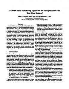
2. The 2D-VLIW Architecture 2D-VLIW (Two-Dimensional Very Long Instruction Words) is a high performance computer architecture that exploits ILP through a bi-dimensional arrangement of the hardware resources and a pipeline datapath. In the 2D-VLIW architecture, the compiler is the unique responsible for assigning operations to the available resources. The architecture is called 2D-VLIW because it fetches large instructions, comprised of single operations, from the memory and executes these operations on a 2D-matrix of functional units through a pipeline. 2D-VLIW follows the EPIC terminology for operations and instructions: an operation corresponds to a RISC-like instruction and an instruction is a group of operations. The 2D-VLIW architectural arrangement is depicted in Figure 1. Figure 1(a) sketches the datapath and its major architectural components. Figure 1(b) details the matrix of functional units (FUs) where four operations can be executed by four FUs at each execution stage EX1 , EX2 , EX3 , EX4 of the pipeline. Figure 1(c) shows all logic blocks and signals inside a 2D-VLIW FU. Results from an FU may be written either into the T emp Register F ile (TRF) or the Global Register F ile (GRF). TRF is a small register bank containing 2 local registers dedicated to each FU. The GRF has 32 registers. The result of an FU is always written into an internal register called F U Register (FUR). Operands input data come from three possible sources: a GRF register, a TRF register, or from the FUR of the FU itself. The SelOpnd1, SelOpnd2 and SelOperation input selection signals are available from the pipeline registers. Program execution over the 2D-VLIW matrix is pipelined. At each clock cycle, one 2D-VLIW instruction (comprised of 16 single operations) is fetched from the memory and pushed into the pipeline stages. On the execution stages, the operations from this
2D−VLIW Instruction
IF/ID Pipeline Register
EX 1 EX1/EX 2Pipeline Register
Register File Bank
Control Unit
EX 2 EX2/EX 3Pipeline Register
EX 3
ID/EX1 Pipeline Register EX3/EX 4Pipeline Register
Functional Unit Matrix
EX 4
(a)
(b)
Operands Operands SelOpnd2
SelOpnd1
SelOperation
Functional Unit
FU Register Global Reg. File
Temp Register File
(c)
Figure 1. An overview of the 2D-VLIW datapath.
instruction are executed according to the number of FUs in each row. Assuming that the architecture has 16 functional units organized as a 4 × 4 matrix, a 2D-VLIW instruction can also be represented as a 4 × 4 operation matrix comprised of 16 operations. Figure 2 shows the execution of instructions A and B in the 2D-VLIW datapath. Since the decode and fetch stages work the same as in a standard processor, we start at the EX1 execution stage. After the ID/EX1 pipeline register has been filled in, the execution starts over the matrix. Figure 2(a) depicts the first execution cycle on the FU matrix. The first row receives data from the ID/EX1 pipeline register. Four functional units from row A1 execute operations addi, addi, addi, addi (instruction A). The dashed arrows indicate which FUs receive the results from these operations. At the second execution cycle, Figure 2(b), operations ld, ld, ld, ld from A2 are running on the second row. At the same time, operations from B1 start onto the first row. At the third execution stage, Figure 2(c), the EX2 /EX3 pipeline register carries information to execute operations from A3 , the FUs in the second row are executing operations ld, ld, addi, st from B2 and the first row (C1 ) of a 2D-VLIW instruction C, starts its execution on the matrix. At the fourth execution stage, Figure 2(d), operations from A4 are running on the fourth row, operations from B3 are running on the third row, operations from C2 are running on the second row and instruction D starts its execution.
addi addi addi addi
A
ld
ld
ld
&
&
&
ld
addi addi
ld
&
A2
1
addi
A4
A1
st
st
A
st
ld
ld
ld
&
&
&
ld
EX /EX 1
B1
2
addi addi
EX2 /EX3
ld
B3
addi
4
st
B4
st
st
st
(a) cycle 1 A1
A
A2
&
&
&
A4
1
ld ld B addi addi + + st
st
st
st
B3
2
A3
&
A2 ld
ld
ld
ld EX /EX 2
B3
3
EX /EX 3
4
B4
1
2
A2
A
A3
EX /EX
B2
EX1 /EX2
D1
1111 0000 EX /EX 0000 1111 1 2 00 11 00 00 00 0011 11 0011 11 0011 11 00 11 C 2 11 0011 0011 11 0011 11 00 11 00 11 00 00 00 EX /EX
A4
2
3
ld addi st
B1 addi st
addi
ID/EX
addi addi addi addi
ld
B1
A1
EX /EX
B2
addi addi &
(b) cycle 2
1111 0000 ID/EX 0000 1111 1 00 11 00 00 00 0011 11 0011 11 0011 11 00 11 C 1 11 0011 0011 0011 00 0011 11 0011 0011 00
& A3
addi addi addi addi
B1
A4
ld addi st B2
B addi addi + +
EX /EX 3
&
1
A2
& A3
addi addi addi addi
addi addi addi addi
ld addi st B2
B addi addi + + st
ID/EX
& A3
addi addi addi addi
ID/EX
A1
A1
&
B4
(c) cycle 3
&
B1
3
B
& EX /EX 3
4
B3
addi addi
+
+
B2 addi addi
st
st
+
+
B3
st
st
B4
EX /EX 3
A4
4
addi addi addi addi
(d) cycle 4
Figure 2. The execution stages of two instructions on the 2D-VLIW architecture.
The 2D-VLIW architecture has a static interconnection model, which is based on TRFs. This is a suitable model for a scheduler matches entire DAGs onto the matrix. Taking into account that DAG operations (nodes) have at most two inputs and DAG edges join operations at consecutive levels, these nodes and edges can be directly mapped onto the FU matrix. Even if the DAG has edges that go beyond the reach of the available interconnections of the matrix, the compiler can assure the right execution by representing the 2D-VLIW matrix as a graph that can be increased according to the DAG’s size and performing the scheduling all over again. As the unique responsible for the mapping of operations onto the hardware resources, the compiler plays an important role in the 2D-VLIW architecture. In order to have a compiler infrastructure generating code for the 2D-VLIW architecture, the Trimaran compiler [Chakrapani et al. 2004] has been adopted. Trimaran does not have a scheduler that captures all 2D-VLIW features however. The scheduling techniques carried out in Trimaran are based on variations of the classical list scheduling. We have found out that approaches dealing with individual operations (like list scheduling does) or small code regions, do not draw a good performance on this architecture when compared to a scheduling looking at larger code regions and taking the functional units interconnection into account. Our scheduling proposal, on the other hand, picks up DAGs from programs and matches these DAGs onto the FU-matrix. The matching is performed by a subgraph isomorphism algorithm.
3. The Subgraph Isomorphism Problem in the 2D-VLIW Architecture Subgraph isomorphism is a very general form of exact pattern matching and a common generalization of many important graph problems including finding Hamiltonian paths, cliques, matchings, girth and shortest paths [Eppstein 1999].
In the classical graph isomorphism problem, two graphs G1 = (V1 , E1 ) and G2 = (V2 , E2 ) are isomorphic, denoted by G1 ∼ = G2 if there is a bijection ϕ : V1 → V2 such that, for every pair of vertices vi , vj ∈ V1 holds that (vi , vj ) ∈ E1 if and only if (ϕ(vi ), ϕ(vj )) ∈ E2 . In the subgraph isomorphism problem, graph G1 = (V1 , E1 ) is isomorphic to graph G2 = (V2 , E2 ) if there exists a subgraph of G2 , for example G02 , such that G1 ∼ = G02 . For certain choices of G1 and G2 there can be exponentially many occurrences so that listing all these occurrences is impractical thus leading to an N Pcomplete decision problem [Garey and Johnson 1979]. Without loss of generality, lets call G1 the input graph and G2 the base graph. Figure 3 shows an example of the subgraph isomorphism. Figures 3(a) and 3(b) show the input graph and the base graph, respectively. The result of the mapping of edges and vertices from graph G1 to graph G2 is the graph in Figure 3(c). Notice that ϕ(a) = 6, ϕ(b) = 5, ϕ(c) = 4, ϕ(d) = 3. 1 a b
d c
2
6
3
5
6 (a) (d) 3 4
4
(a) Input graph G1
(b) Base graph G2
5 (b) (c)
(c) Graph G02
Figure 3. Example of the Subgraph Isomorphism.
Instruction scheduling has been one of the most complex tasks for a 2D-VLIW compiler mostly because the scheduler has to capture several hardware features such as FU-matrix size and topology, number of global and temporary registers and take all of them into account at the scheduling time. An instruction scheduling scheme based on subgraph isomorphism can minimize part of this complexity by representing the functional units and their interconnections through a base graph whereas the operations of the input DAG and their dependencies are represented by the input graph. Given an input DAG G1 and the FU-matrix represented as a base graph G2 , the scheduler goal is to find a subgraph G02 (represented as hardware resources inside the matrix) that matches to G1 . The mapping of operations onto the FU-matrix leads to a complete 2D-VLIW instruction. Figure 4 depicts the 2D-VLIW instruction scheduling as a subgraph isomorphism problem. Notice that the functional units of the matrix and their interconnections are nodes and edges of the base graph. By looking at the scheduling result, we can realize that each position of the 2D-VLIW instruction has one operation which will be executed as the instruction goes down the FU-matrix.
4. A Subgraph Isomorphism Algorithm to Schedule 2D-VLIW Instructions Since subgraph isomorphism problems were already proved as N P-complete problems [Ullmann 1976], adopting efficient algorithms is a mandatory condition to use solutions to solve them. We have carried out a set of heuristics and used the main ideas from the VF subgraph isomorphism library [Cordella et al. 2001] to perform the
Base Graph
Input Graphs addi
addi addi
addi
&
addi
EX1/EX 2Pipeline Register
ld
+
+
ld
+
+
st
EX2/EX 3Pipeline Register
addi
&
111 000 000 111 000 111 000 111 000 111 000 111
000 000 111 000 111 addi 111 000 111 000 111 000 111
addi
EX3/EX 4Pipeline Register
000 111 000 111 000 111 000 111 111 000 000 111 000 111 000 111 000 111 000 111 000 111 000 111 000 111 000 111 000 111 000 111
st
Scheduling Result
addi addi
ld
+
&
addi
+
st
111 000 0000 1111 000 111 000 111 0000 1111 000 111 000 0000 1111 000 000 111 0000111 1111 000 111 addi 111 000 111 0000 1111 000 000 111 0000111 1111 000 111 000 111 0000111 1111 000 000 111 000111 111 000 111 0000111 1111 000 111 000 111 000 0000 1111 000 000 111 000 111 0000 1111 000 111 000 111 000 111 0000 1111 000 000111 111 000 0000111 1111 000 111
Figure 4. 2D-VLIW Instruction Scheduling Strategy.
2D-VLIW scheduling based on the subgraph isomorphism strategy. The VF algorithm finds an isomorphism if there exist one and can determine the best isomorphism (optimal result). Further optimizations were added to this library to make it suitable for our purposes. For example, the original worst-case time complexity of VF algorithm is O(V !V ), where V = #vertices of the input graph. One of our optimizations consists in determining a time constraint (≤ 8 sec.) where the VF algorithm should find an isomorphism for each DAG. If the isomorphism is not found within this time constraint, one optimization is performed to aid the scheduling. By performing the experiments, we could realize that these optimizations were indeed useful to schedule DAGs having more than a hundred vertices. The inputs of the 2D-VLIW instruction scheduling strategy are DAGs generated by the Trimaran compiler and a base graph built in a specific procedure. The DAGs are passed to the scheduler on a hyperblock [Mahlke et al. 1992] basis, i.e., all the DAGs from a hyperblock i are scheduled before going to the next hyperblock p, p > i. Our algorithm takes these DAGs along with operation’s latency information and performs the matching between the DAG and the base graph. Despite taking operations’ latency and explicit data dependencies to schedule instructions, our algorithm also obeys some nonexplicit data dependency such as saving passing parameters before procedure calls, and so on. Algorithm 1 outlines the 2D-VLIW instruction scheduling strategy. First of all, we execute the topological order procedure (Line 1) to perform a topological ordering in the input DAG G1 . Procedure subg iso sched (Line 2) finds a subgraph G02 , G02 ⊆ G2 , isomorphic to G1 . This procedure uses the VF subgraph isomorphism library to find out subgraph G02 . If subgraph G02 is not found (Lines 3-8) the scheduler chooses one heuristic (Lines 4-6) and runs it over the input parameters. Variable tag (Line 4) acts as a heuristic selector. Heuristic base graph resize (Line 5) increases the base graph size in order to speed up the subgraph isomorphism procedure. The last heuristic, DAG stretch (Line 6), transforms DAG G1 into a more flexible graph
Algorithm 1 2D-VLIW Subgraph Isomorphism Scheduling Algorithm INPUT: An input graph G1 and a base graph G2 OUTPUT: Set of 2D-VLIW instructions Sched(DAG: G1 , BASE GRAPH: G2 ) 1) topological order(G1 ); 2) G02 =subg iso sched(G1 , G2 , tag); 3) while (G02 == N U LL) 4) switch(tag) 5) case 1 : base graph resize(G2 ); 6) case 2 : DAG stretch(G1 ); 7) G02 =subg iso sched(G1 , G2 , tag); 8) end while 9) create 2D-VLIW instruction(G02 ); so that it can be easily matched to G2 . Observe that only one heuristic is used after each unsuccessful execution of the subg iso sched procedure. Each heuristic is executed following a sequential order according to the numbers in Lines 5 and 6. After the scheduling is found, a 2D-VLIW instruction is created (Line 9). It should be clear that the time constraint is set in the subg iso sched procedure. 4.1. Topological Ordering Procedure The topological ordering procedure provides the vertices ordering for the subg iso sched procedure. A bad vertex ordering can increase the number of backtracking steps of the isomorphism algorithm, resulting in a poor scheduling performance. We have carried out two simple topological ordering algorithms: a breadth first search (BFS) and critical path ordering. The first strategy performs a breadth search over the input DAG. The goal is to order the DAG in a way that direct descendants of a node are kept as close as possible to their parents. At scheduling time, an ancestor node will be always scheduled first and their descendants will be scheduled as soon as possible. The second topological ordering algorithm is based on the Best Fit Decreasing heuristic from the Bin-Packing Problem [Johnson 1974]. The idea is to let vertices in the DAGs’ critical path to be scheduled first, starting from the root to the leaves. This algorithm has shown to be very useful to avoid cases where short branches of a DAG use base graph regions that could be used for nodes of the critical path. 4.2. Heuristic 1: Base Graph Resizing This heuristic is run when a base graph G2 is not large enough to have a subgraph isomorphic to DAG G1 . The heuristic enlarges a base graph 2-fold, thereby forming up a new larger base graph. One can see this heuristic as a base graph “unrolling” method once the enlargement of the base graph is given by doubling (unrolling) its nodes and interconnections along the time, like in the software pipeline techniques [Aiken and Nicolau 1988]. Figure 5 exemplifies an unrolling of a single base graph, the FU-matrix in Figure 5(a), into a new larger base graph, the interconnected FU-matrices in Figure 5(b). For the sake of simplicity we left out the pipeline details. Looking at FU-matrix B, we can notice that the FUs in row n from this matrix, 2 ≤ n ≤ 4, have more edges than the FUs in the same
row from FU-matrix A. These edges indicate that an FU from an unrolled matrix B can read values produced by FUs from matrix A and matrix B itself. Figure 5(c) shows the interconnection details from two nodes of FU-matrix A to two nodes of FU-matrix B.
A
A
B
A
B
(a) Single base graph=one FU- (b) Larger base graph=two FU- (c) Interconn. details between FUmatrix matrices matrix A and FU-matrix B Figure 5. Example of base graph unrolling.
In Figure 6, one can observe that the input DAG in 6(a) cannot be scheduled onto a base graph comprised of just one FU-matrix. This scheduling cannot happen because node 2 has 3 descendants and the nodes of the base graph have only 2 descendants. The solution is to unroll the base graph to produce nodes with 3 descendants. Remember from Figure 5(b) that a base graph comprised of 2 FU-matrices has nodes with more than 2 descendants. After unrolling the single base graph, in Figure 6(b), we obtain the final successful scheduling in Figure 6(d). 1
1
1
1
2
2
2
3
3
2
4
4
5
A 5
3
4
(a) Input DAG
A
(b) Single base graph
5
3
4
(c) Input DAG
B
(d) Larger base graph
Figure 6. Base graph resize example.
4.3. Heuristic 2: DAG Stretch The DAG stretch heuristic acts as a mechanism to make the input DAG flexible enough to be allocated onto the 2D-VLIW FU-matrix. At scheduling time, the scheduler struggles to match input DAGs onto the base graph. If the input DAG is too complex such that the scheduler cannot find a subgraph isomorphic to the input DAG, the scheduling algorithm resorts to the DAG stretch heuristic. The heuristic converts single nodes of the input DAG into a new class of nodes named g-nodes in order to let the scheduler can use different base-graph regions to perform the scheduling. The single nodes are the nodes with the most number of descendants. This choice comes to the intuition that nodes with many descendants are most likely, the cause of backtrackings. Figure 7 outlines how this heuristic works.
In Figure 7(a) node 2 has 3 descendants and the base graph, Figure 7(b), has enough available nodes to match the input DAG. However, the mapping of DAGs edges onto the FUs interconnections (TRFs) enables the subgraph isomorphism algorithm to explore only TRFs-connected nodes. Our solution is to convert node 2 into 2g (global node) that allows its descendants to be scheduled onto any node of the base graph. 000 111 0000111 1111 000 111 000 0000111 1111 000 000 111 0000 1111 000 000 111 0000111 1111 000 111 000 111 0000 1111 000 111 0000111 1111 000 111 000 000 111 0000 1111 000 000 111 0000111 1111 000 111 000 111 0000111 1111 000 2 111 000 0000111 1111 000 000 111 000111 111 000 0000 1111 000 111 0000 1111 000 111 000111 111 000 111 000 0000111 1111 000 000111 111 000 111 0000111 1111 000 111 000 111 000 0000 1111 000 000 0000111 1111 000 000111 111 000111 111 000 111 0000111 1111 000 111 000 111 000 0000 1111 000 000111 111 000 111 0000111 1111 000 111 000 111 000 0000 1111 000 000 111 000 111 0000 1111 000 000111 111 000 0000111 1111 000 111
1
1
2
A
000111 111 000 0000 1111 111 000 000 0000 1111 000111 111 000 111 0000 1111 000111 111 000 0000 1111 000111 111 000 0000 1111 0000111 1111 000 111 000 000 000111 111 000 111 0000 1111 000 111 000111 111 000 0000111 1111 000 000111 111 000 111 0000111 1111 000 111 000 111 000 0000 1111 000 000111 111 000 000 0000111 1111 000111 111 000 111 0000111 1111 000 111 000 111 000 0000 1111 000 000111 111 000 111 0000111 1111 000 111 000 111 000 0000 1111 000 000 111 000 111 0000 1111 000 111 000111 111 000 0000111 1111 000 111 000 111 0000 1111 000 111 0000000 1111 000 111 000 111 0000 1111 000 111 000 111 0000 1111 000 000 111 0000111 1111 000 111
B
111111 000 000 0000111 1111 000 000111 111 000 111 0000111 1111 000 111 000 111 000 0000 1111 000 000111 111 000 111 0000111 1111 000 111 000 111 000 0000 1111 000 000 000111 111 0000 1111 000 111 000 000111 111 0000111 1111 000 111 000 111 000 111 0000 1111 000 000111 111 000 111 0000111 1111 000 111 000 111 000 0000 1111 000 000111 111 0000111 1111 000 000 000111 111 000 111 0000111 1111 000 111 000 111 000 0000 1111 000111 111 000 0000000 1111 000 111 000111 111 000 0000 1111 000 111 000 111 0000 1111 000 111 000 111 000 000111 111 0000111 1111 000 000 111 0000 1111 000 111 000 111 0000 1111 000 111 000 111 0000111 1111 000 111 000 111 0000 1111 000 111 0000000 1111 000 111
C
5
3
4
111111 000 000 000111 111 000 111 000 111 000 000111 111 000 111 000 111 000 000111 111 000 0000111 1111 000 000111 111 000 111 0000111 1111 000 111 000 111 0000 1111 000000 111 000 111 0000000 1111 000 111 000 111 000 0000 1111 000 111 000111 111 0000 1111 000 000 111 0000111 1111 000111 111 000 000 111 000 111 000 111 000 111 000 111 000 111 000 111 000111 111 000 111 000 111 000 000 111 000 111 0000 1111 000111 111 000 111 0000111 1111 000 111 000 111 000 0000 1111 000 000 111 000 111 0000 1111 000 000111 111 000 111 0000111 1111 000 111 000 111 000 0000 1111 000 000111 111 000 0000111 1111 000 111
D
(a) Input DAG
(b) Scheduling result 111 000 0000 1111 000 111 000 111 0000 1111 000 000 111 0000111 1111 000 111 000 111 0000 1111 000 000 111 0000111 1111 000 111 000 111 0000 1111 000 0000111 1111 000 111 000 000 111 0000111 1111 000 111 000 0000 1111 000 2g 111 000 111 0000111 1111 000 111 000111 111 000 111 0000111 1111 000 111 000 000 111 000 0000 1111 000111 111 000 111 0000111 1111 000 111 000 111 000 0000 1111 000111 111 000 0000000 1111 000 111 000111 111 000 111 0000111 1111 000 111 000 0000 1111 000 000 111 000111 111 000 111 0000111 1111 000 111 000 111 000 0000 1111 000 000 111 000 111 0000 1111 000 000111 111 000 111 0000111 1111 000 111 000 111 000 0000 1111 000 111
1
1
2g
A
000111 111 000 111 0000 1111 111 000 0000 1111 000000 111 000 111 0000 1111 000 111 000 0000 1111 000111 111 000 111 0000 1111 000111 111 000 111 0000111 1111 000 111 000 111 000 0000 1111 000111 111 000 111 0000000 1111 000 111 000 111 000 0000 1111 000 000111 111 000 0000111 1111 000 111 000 111 000111 111 000 111 0000111 1111 000 111 0000 1111 000 000 000111 111 000 111 0000111 1111 000 111 000 111 000 0000 1111 000 000 111 000 111 0000 1111 000 111 000111 111 000 0000111 1111 000 111 000 111 000 111 0000 1111 000 000 111 0000 1111 000 000 111 0000111 1111 000 111 000 111 0000 1111 000 000 111 0000111 1111 000 111 000 111 0000 1111 000 111
B
000111 111 000 111 0000111 1111 000 111 111 000 0000 1111 000000 111 000 111 0000000 1111 000 111 000 111 000 0000 1111 000 000111 111 000 111 0000111 1111 000 111 000111 111 000 111 0000111 1111 000 111 000 0000 1111 000 111 000111 111 000 111 0000000 1111 000 111 000 111 000 0000 1111 000 000111 111 000 0000111 1111 000 111 000111 111 000 111 0000111 1111 000 111 000 111 000 0000 1111 000 000 111 000 111 0000 1111 000 000111 111 000 111 0000111 1111 000 111 000 111 000 0000 1111 000 111 000 111 000111 111 0000111 1111 000 111 000 0000 1111 000 111 000 000 111 0000 1111 000 000 111 0000111 1111 000 111 000 111 0000 1111 000 000 111 0000111 1111 000 111 000 111 0000 1111 000 111
C
5
3
4
000111 111 000 111 111 000 000000 111 000 111 000 111 000 4 000111 111 000 3 111 000111 111 000 111 0000111 1111 000 111 000 111 000 0000 1111 000 000 111 000 0000 1111 000 000111 111 000 111 0000111 1111 000 111 000 111 000 111 0000 1111 000 111 000111 111 0000111 1111 000 000 0000 1111 000 111 000 111 000 111 000 111 000 000 000111 111 000 5 111 111 000 111 000 111 000 111 000 111 000 111 000 111 000111 111 0000111 1111 000 111 000 0000 1111 000 000 111 000 111 0000 1111 000 000111 111 000 111 0000111 1111 000 111 000 111 000 0000 1111 000 000111 111 000 111 0000111 1111 000 111 000 111 000 0000 1111 000 111
D
(c) Input DAG with a g-node
(d) Scheduling result after a g-node insertion Figure 7. DAG stretch example.
One can notice that the g-node makes the input DAG flexible enough enabling it to use other nodes of the base graph that were not initially available. Such flexibility is owed to the global registers usage since a global register data can be read from any functional unit of the FU-matrix through the pipeline registers. In other words, the conversion of node 2 into 2g indicates that node 2g writes its result to an available global register, hence making it possible to its descendants nodes to be scheduled onto any functional unit.
5. Experimental Results This Section presents the performance results of the 2D-VLIW scheduling. We compare the results of our approach based on subgraph isomorphism with a greedy list scheduling algorithm. This list scheduling is described in Subsection 5.1. We have performed three experiments that measure the number of 2D-VLIW instructions per program, the number OPC enabled by each scheduling type, and the number of OPI. The results of the experiments are presented in Subsection 5.2. All the experiments were carried out using programs of the SPEC and MediaBench suites compiled with the Trimaran compiler infrastructure. 5.1. A 2D-VLIW Greedy List Scheduling Algorithm The 2D-VLIW list scheduling algorithm is a greedy list scheduling solution for the 2DVLIW FU-matrix. As usual, it schedules each individual node according to its order in the ready set. Given an operation i to be scheduled, the algorithm tries to choose an available FU at the same matrix as its ancestors in order to increase the program OPI. If
such FU is not available, the algorithm chooses the first available FU in the next matrix following the interconnection constraints of its parents. Like the isomorphism algorithm (discussed in Section 4), the list scheduling strategy backtracks whenever there is no possible scheduling for the current node. Despite its exponential time complexity, the backtracking procedure is a necessary step to make sure that the scheduling follows the DAG’s nodes dependency. Algorithm 2 outlines the main steps of the 2D-VLIW list scheduling strategy. Except for Lines 2, 5, and 7, the steps of the algorithm look like the same as in Algorithm 1. Observe that the DAG Stretch heuristic can also be applied to the input parameters in Algorithm 2. Moreover, the same time constraints used in Algorithm 1 are also applied to Algorithm 2. Algorithm 2 Greedy List Scheduling Algorithm INPUT: An input graph G1 from a hyperblock OUTPUT: Set of 2D-VLIW instructions LS Sched(DAG: G1 ) 1) topological order(G1 ); 2) G02 =greedy ls sched(G1 ); 3) while (G02 == N U LL) 4) DAG stretch(G1 ); 5) G02 =greedy ls sched(G1 ); 6) end while 7) create 2D-VLIW instruction(G02 ); 5.2. Results The first experiment shows the number of 2D-VLIW instructions obtained by each scheduling algorithm and their respective scheduling time. The results in Table 1 has a straight impact on the final code size and performance of the programs since programs that have more instructions will require more instruction fetch cycles to the memory. The last column indicates the improvement of the subgraph isomorphism scheduling time when compared to the list scheduling time. Columns 2 and 3 represent the number of instructions and the scheduling time (seconds) of the List Scheduling (LS) algorithm. Columns 4 and 5 show the same values (number of instructions and scheduling time) considering the Subgraph Isomorphism Scheduling (SIS) algorithm. The results in Table 1 show that the isomorphism scheduling strategy leads to fewer 2D-VLIW instructions than the greedy list scheduling for all the evaluated programs. The isomorphism scheduler time performance were up to 95% better than the list scheduling. The scheduler performance gains of our strategy can be observed for all the programs (Column Improv.). We have also performed an experiment comparing the time performance of our scheduling strategy to the greedy list scheduling algorithm. The average time speedup of our scheduling over the greedy list scheduling algorithm is 8.21. The worst running performance of the list scheduling is owing to two reasons: 1) its local view of the scheduling process; 2) the backtracking procedures running every time a vertex does not match to the base architecture graph. Despite not being shown, we believe that a list scheduling algorithm that does not perform the backtracking, provides a better performance at the expense of a larger global register usage.
Table 1. Number of 2D-VLIW instructions and Scheduling Time of the List Scheduling (LS) and the Subgraph Isomorphism Scheduling (SIS).
Programs 176.gcc 175.vpr 181.mcf 197.parser 255.vortex 256.bzip2 300.twolf epic g721.decode g721.encode gsm.decode gsm.encode pegwit 168.wupwise 179.art 183.equake
LS 158,300 401,573 58,483 54,217 9,689 9,243 71,514 86,912 110,602 128,608 21,020 24,875 99,688 141,371 8,732 634 1,524 1,236 1,533 1,447 10,557 1,831 13,852 5,034 14,128 10,634 9,336 6,869 10,479 3,583 10,787 5,150
SIS 108,786 48,967 43,511 7,525 7,782 1,264 45,410 6,666 75,235 5,679 17,109 5,184 84,344 23,843 1,953 151 2,343 94 2,331 91 9,136 1,113 11,810 1,885 11,159 2,171 6,666 1,096 14,800 1,112 7,243 655
Improv. (87%) (86%) (86%) (92%) (95%) (79%) (83%) (76%) (92%) (93%) (39%) (62%) (79%) (84%) (68%) (87%)
The next experiment compares the OPC and OPI achieved by both scheduling algorithms when considering all the programs. Unlike other approaches based on the program’s kernels, we compute the OPC and OPI by the whole program code source. The values in Table 2 indicate the OPC and OPI (in parenthesis), respectively. Likewise Table 1, LS represents the results obtained by the List Scheduling algorithm and SIS represents the results of the Subgraph Isomorphism Scheduling algorithm. Moreover, we compute the average and standard deviation of the OPC and OPI in each algorithm. The isomorphism scheduling algorithm outperforms the greedy list scheduling for all programs. The average OPC and OPI of the subgraph isomorphism scheduling are about 1.5× better than the values produced by the list scheduling. Actually, the maximum OPC and OPI values achieved by the subgraph isomorphism is up to 3.12× (program 255.vortex) better than the greedy list scheduling. Another interesting result shows up when we compare the OPC achieved by a subset of the programs in Table 2 (programs 179.art, 256.bzip2, 183.equake, and 197.parser) with the results reported in [Coons et al. 2006] when using the same subset. The peak OPC (Annealed IPC) obtained in [Coons et al. 2006] for these programs is 6.4, 3.0, 2.7, and 2.4, leading to an average OPC of 3.62. For this same program subset, the average OPC achieved by our subgraph isomorphism scheduling is 3.45. Most important, the scheduling algorithm described in [Coons et al. 2006] does not consider compiler time constraints to achieve these peak performance. On the other hand, all our results were obtained according to time constraints added into our scheduling algorithm.
Table 2. OPC and OPI
Program 176.gcc 175.vpr 181.mcf 197.parser 255.vortex 256.bzip2 300.twolf epic g721.decode g721.encode gsm.decode gsm.encode pegwit 168.wupwise 179.art 183.equake Average St. Dev.
LS 2.27 (6.17) 2.50 (2.34) 5.00 (4.99) 2.20 (2.03) 1.09 (2.25) 2.47 (2.47) 2.18 (1.93) 2.61 (1.30) 2.23 (2.23) 2.24 (2.24) 2.47 (2.47) 2.55 (2.55) 4.32 (4.30) 2.23 (2.23) 2.36 (2.36) 2.20 (2.30) 2.55 (2.76) 0.9 (1.2)
SIS 3.14 (8.99) 3.70 (3.15) 6.60 (6.22) 3.59 (3.20) 3.41 (3.31) 3.20 (3.03) 2.76 (2.28) 4.49 (5.84) 3.52 (3.44) 3.48 (3.41) 3.10 (2.86) 3.20 (2.99) 5.07 (5.44) 3.38 (3.13) 3.51 (1.67) 3.52 (3.28) 3.72 (3.89) 0.9 (1.8)
6. Related Work and Discussion In this Section we outline a number of research work proposing new instruction scheduling techniques for processor architectures based on multiple processing elements like 2D-VLIW. Algorithms with a global view of data flow graphs aiming at reducing the inter-cluster communication in clustered VLIW processor architectures are proposed in [Nagpal and Srikant 2004]. The authors’ proposal comes through a generic graph matching algorithm for scheduling instructions into a clustered VLIW datapath. The algorithm creates a bipartite graph consisting of a set of instruction nodes including all the instructions in the ready list and a set of resource nodes including all the resources in all the clusters. They have drawn about 16% − 28% performance improvement over different scheduling strategies. The DRESC (Dynamically Reconfigurable Embedded System Compiler) compiler is used for a coarse-grained reconfigurable architecture called ADRES [Mei et al. 2001]. The compiler adopts a MODULO scheduling algorithm to place and route instructions. The algorithm uses a graph-based architecture representation to model hardware resources. The scheduler’s objective is to engineer a schedule for one iteration of the loop such that this same schedule is repeated at regular intervals with respect to intra or inter-iteration dependency and resource constraints. This interval is named the initiation interval(II), essentially reflecting the performance of the scheduled loop. Experimental results show that up to 28.7 IPC can be achieved over tested loops. RAWCC is a compiler developed for the RAW architecture [Lee et al. 1998]. The scheduling on a RAW machine consists of orchestrating the parallelism within a basic
block across the RAW tiles and handling the control flow across basic blocks. This basic block orchestration consists of assigning instructions to processing units, and the explicit orchestration of communication across a mesh interconnect. Instruction scheduling is performed by a list scheduling algorithm. In the experimental results using dense matrix applications, the applications compiled with the RAWCC compiler achieved speedups ranging from 1.48 − 38.35 over a MIPS compiler provided by Machsuif [Lee et al. 1998]. An instruction scheduling algorithm for the TRIPS architecture is presented in [Nagarajan et al. 2004]. Basically, the Static Placement, Dynamic Issue (SPDI) Scheduling algorithm is a classical list scheduling solution augmented with several heuristics. The heuristics are responsible for balancing the reduction of communication latencies - on a topology with non-uniform latencies between resources - with the exposure of instruction-level parallelism, so as to minimize ALU contention and maximizing instruction density. Despite acting on architectures based on multiple processing elements (like 2DVLIW), we can notice that these proposals are quite different of our work. Most of them consist in variations of the classical list scheduling algorithm to schedule operations to the hardware resources. Our scheduling strategy proposes to deal with the scheduling problem in another way so that new algorithms should be used.
7. Conclusions and Future Work A new instruction scheduling algorithm based on subgraph isomorphism theory was presented in this paper. The algorithm has been used as a basic scheduler for an architecture named 2D-VLIW. The algorithm considers DAGs of a program as input graphs and the functional units and their interconnections are represented by a base graph. The objective is to find a subgraph of the base graph which is isomorphic to the input graph. By comparing the average OPC and OPI achieved by our scheduling technique to the greedy list scheduling algorithm, the subgraph isomorphism algorithm obtains 3.72 and 3.89, respectively, whereas the greedy list scheduling values are 2.55 and 2.72. All the programs have less 2D-VLIW instructions when scheduled with the subgraph isomorphism strategy. Interesting enough, our scheduling algorithm achieves a time speedup of 8.21 over the greedy list scheduling algorithm. Future research is focused on plugging scheduling and register allocation together using the subgraph isomorphism strategy. We are also experimenting new parameters for the Base Graph Resize heuristic. Furthermore, we intend to evaluate this scheduling algorithm under other architectures based on multiple processing elements with dynamic or fully interconnecting schemes.
References Aiken, A. and Nicolau, A. (1988). Limits on Multiple Instruction Issue. In Proc. of the ACM Conf. on PLDI, pages 308–317. ACM Press. Chakrapani, L. N., Gyllenhaal, J., Mei, W., Hwu, W., Mahlke, S. A., Palem, K. V., and Rabbah, R. M. (2004). Trimaran - An Infrastructure for Research in Instruction-Level Parallelism. Lecture Notes in Computer Science, 3602:32–41.
Coons, K. E., Chen, X., Kushwaha, S. K., Burger, D., and McKinley, K. S. (2006). A Spatial Path Scheduling Algorithm for EDGE Architectures. In Proc. of the 12th ACM Int. Conf. on ASPLOS, pages 40–51. ACM Press. Cordella, L. P., Foggia, P., Sansona, C., and Vento, M. (2001). An Improved Algorithm for Matching Large Graphs. In Proc. of the 3rd IAPR TC15 Workshop on Graph-Based Representations, pages 149–159, Ischia - Italy. Eppstein, D. (1999). Subgraph Isomorphism in Planar Graphs and Related Problems. Journal of Graph Algorithms and Applications, 3(3):1–27. Faraboschi, P., Fisher, J. A., and Young, C. (2001). Instruction Scheduling for Instruction Level Parallel Processors. Proc. of the IEEE, 89(11):1638–1658. Garey, M. R. and Johnson, D. S. (1979). Computers and Intractability: A Guide to the Theory of NP-Completeness. W. H. Freeman and Company. Henning, J. (2000). SPEC CPU2000: Measuring CPU Performance in the New Millenium. IEEE Computer, 33(7):28–35. Johnson, D. S. (1974). Fast Algorithms for Bin Packing. Journal of Computer and System Sciences, 8:272–314. Lee, C., Potkonjak, M., and Smith, W. H. (1997). MediaBench: A Tool for Evaluating and Synthesizing Multimedia and Communications Systems. In Proc. of the 30th Int. Symp. on MICRO, pages 330–335, Research Triangle Park - North Carolina. IEEE Computer Society. Lee, W., Barua, R., Frank, M., Srikrishna, D., Babb, J., Sarkar, V., and Amarasinghe, S. (1998). Space-Time Scheduling of Instruction-Level Parallelism on a Raw Machine. In Proc. of the 8th Int. Conf. on ASPLOS, pages 46–57. ACM Press. Maheswaran, M. and Siegel, H. J. (1998). A Dynamic Matching and Scheduling Algorithm for Heterogeneous Computing Systems. In Proc. of the 7th Heterogeneous Computing Workshop, pages 57–69. IEEE Computer Society. Mahlke, S. A., Lin, D. C., Chen, W. Y., Hank, R. E., and Bringmann, R. A. (1992). Effective Compiler Support for Predicated Execution Using the Hyperblock. In Procs of the 25th IEEE/ACM Int. Symp. on MICRO, pages 45–54. IEEE Computer Society. Mei, B., Vernalde, S., Verkest, D., Man, H. D., and Lauwereins, R. (2001). DRESC: A Retargetable Compiler for Coarse-Grained Reconfigurable Architectures. In Proc. of the IEEE Int. Conf. on FFT, pages 166–173. IEEE Computer Society. Nagarajan, R., Kushwaha, S. K., Burger, D., McKinley, K. S., Lin, C., and Keckler, S. (2004). Static Placement, Dynamic Issue (SPDI) Scheduling for EDGE Architectures. In Proc. of the 13th ACM Int. Conf. on PACT, pages 74–84. IEEE Computer Society. Nagpal, R. and Srikant, Y. N. (2004). A Graph Matching Based Integrated Scheduling Framework for Clustered VLIW Processors. In Proc. of the 2004 Int. Conf. on Parallel Processing Workshops, pages 446–451. IEEE Computer Society. ommited for blind review. Ullmann, J. R. (1976). An Algorithm for Subgraph Isomorphism. Association for Computing Machinery, 23(1):31–42.
Journal of the