Specific locations in the yard are for containers of dangerous goods, and ... normal, dangerous goods, or reefer) are stacked on different bays in the yard at the ...
Proceedings of the Second International Intelligent Logistics Systems Conference 2006
AN INTEGRATED APPROACH IN OPTIMISING CONTAINER PROCESS AT SEAPORT CONTAINER TERMINALS Andy Wong and Erhan Kozan Queensland University of Technology Brisbane, Australia {a3.wong,e.kozan}@qut.edu.au
ABSTRACT A container terminal yard acts as an interface/buffer between ships and the hinterland for container transfers. To achieve shorter ship service time, hence minimum ship delay and greater throughput of the port, containers in the yard should be stored at the most suitable location. However, such locations are limited resources and may not always be available. On the other front, the container process is analogous of a multi-stage flowshop with parallel machines. To increase the efficiency of the port, it is also important to reduce machine slack and blocking times. This paper investigates container storage location, and the sequencing and scheduling of machine operations in the port. An integrated approach is proposed to minimise ship service time. Meta-heuristic algorithms are developed to solve the problem. Numerical investigation is also presented. Key Words: Optimisation, Scheduling, Yard Planning 1. INTRODUCTION At seaport terminals, inbound containers are unloaded from ships and stored in the yard before further transfer to hinterland by rail or by road. The yard is also a temporary storage for outbound containers moved into the yard by rail or by road for loading to ships. To minimise ship service time, containers should be stored at the most suitable location. Storage space close to the berth is a limited resource. The problem is to optimise the storage location to minimise the total travelling time of yard machines (YMs) like straddle-carriers, fork-lift, reach-stackers, and terminal trucks. A reduction in the travelling time of YMs has the potential of increasing the throughput of the port, and of lowering fuel consumptions. From bow to stern and from port side to starboard side of a ship, containers are stacked below and above deck supported by removal hatch cover [FM 55-17 Cargo Specialists' Handbook]. The transverse row of container cells is referred to as a bay. A container ship can carry several thousand TEUs (twenty-foot equivalent units) and has a length of 250 m or longer. In the yard, containers are stacked in rows and a number of bays in each row. Before a ship arrives, the terminal operators should be informed of the number of containers on the ship and how they are stored. The operators must decide on which berth is to assigned to the ship, the number of quay cranes (QCs) for loading and unloading, the storage location on the yard, as well as the number of YMs (for example, tractors, fork-lift, straddle-carriers) to work on the ship. An unloading plan is also prepared, taking into consideration the ship balance and separation between QCs. After the ship is berthed, inbound containers are allowed to stay in the yard for a few days free of storage charge.
23.1
Proceedings of the Second International Intelligent Logistics Systems Conference 2006
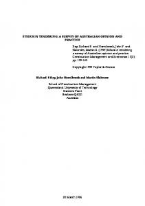
Specific locations in the yard are for containers of dangerous goods, and reefers (containers with refrigeration) which require power. Other containers of the same type (20 or 40 feet, normal, dangerous goods, or reefer) are stacked on different bays in the yard at the discretion of the terminal operator.
Figure 1. Storage of containers on ship and in the yard The export process is the reverse of the import process. A few days before the scheduled arrival of the ship, the port accepts outbound containers to the yard until a certain cut-off time. Prior to loading containers to the ship, a plan is prepared by taking into account the weight category, the final destination and the type of each container, the maximum allowable weight for each stack, as well as maintaining the overall balance of the ship. Outbound containers taken into the port by rail have a predicable arrival schedule, but those arrive by road are in random fashion. There is a one-to-one correspondence between the storage location on ship and the one in the storage yard. Without considering weight and other restrictions, a re-arrangement of storage location of containers on a ship can be achieved through a re-allocation of storage in the yard. In Figure 2a, storage location at A and B in the yard are associated with a and b on the ship. If a is to swap with f (see Figure 3b), this can be achieved by swapping A and F instead (see Figure 3c).
Figure 2a. Storage of containers on the ship and in the yard
23.2
Proceedings of the Second International Intelligent Logistics Systems Conference 2006
Figure 2b. Swapping storage locations on the ship
Figure 2c. Swapping storage locations in the yard
There has been a growing interest on container terminal operations among researchers over the past decade. [Steenken et al., 2004] gives classification of problems surrounding terminal operations and suggestions for future research. The paper also points out that stacking and storage logistics are becoming increasingly important as a result of growth in container traffic, and also becoming more complex and sophisticated. [Kim and Park, 2003] propose a MIP model for optimising the storage location of outbound containers by minimising the total travel costs of containers between the marshalling area and the allocated space. The "leastduration-of-stay" (DOS) and "sub-gradient optimisation" heuristic (SGHA) are investigated in this particular paper. Results show that on average the objective values from DOS are 5% higher than those from SGHA, yet DOS is much faster. [Kim and Kim, 2002] study a cost model consisting of space cost, investment cost of transfer cranes, and the operating cost of transfer cranes and trucks. When retrieving containers from a stack, rehandling may be requires unless the order is strictly from the top to the bottom. A container location model is proposed in [Preston and Kozan, 2000], which is concerned with the layout of the storage area and the rehandling requirement of containers. Genetic algorithm is applied to minimise the total travelling and setup time of YMs. Sensitivity analysis is performed with the aid of simulation. The paper studies the effect of parameters, like storage utilisation, loading schedule and the number of YMs on the total handling and transfer time of containers. [Bish et al., 2001] put forward a model for optimising the storage location in the yard for inbound containers. The problem is formulated as an assignment problem. The paper also presents an analysis of the Assignment Problem Based (APB) heuristic for solving the vehicle-scheduling-location problem. A network model for container transfers at multimodal terminals is suggested in [Kozan, 2000]. The model considers various factors affecting the total including the storage area, QC and YMs. The sensitivity analysis of QC and YMs is also presented. [Wong and Kozan, 2005] investigate the relationship between quay cranes, automated straddle carriers and container storage locations. A model is developed to optimise the container process and the problem is solved using meta-heuristic techniques. The next section investigates a model for optimising the storage allocation, taken into account the loading and unloading position of containers.
2. STORAGE ALLOCATION MODEL (SAM) When servicing a ship, a QC may unload all inbound containers before loading any outbound containers. Alternatively, the QC may avoid excessive motion by completing all loading/unloading at one ship bay before moving on to the other. The second strategy is more space efficient, because storage space for outbound containers in the yard may be re-usable
23.3
Proceedings of the Second International Intelligent Logistics Systems Conference 2006
for the inbound containers of the same ship. In this section, the first strategy is assumed. If the second strategy is to be applied, the ship can be considered as two ships - one with only inbound containers and the other with only outbound containers. When transferring a container between yard and the marshalling area, the path depends on the configuration of yard, and other operation constraint (for example, the minimum radius of curvature of YM in making a turn). Suppose YMs move either along or perpendicular to the berth-line during the transfer of containers between the marshalling area and the yard. In Figure 3a, containers C1 and C2 unloaded at A1 and A2 and are to be stored at either L1 and L2 in the yard. The question is whether the total distance is shorter by moving A1 to L1 and A2 to L2 , or the other combination as in Figure 3b. The total distance perpendicular to the berth-line is a constant, and only the total distance along the berth-line ( A1 B1 + A2 B2 ). To minimise the travelling time of YMs, the overlapping of path ( A1 B2 + B1 A2 ) should be avoided.
Figure 3a. Path of container transfers
Figure 3b. Overlapping Paths
Containers of the same type (20-foot or 40-foot) are normally stacked together on the ship and in the yard. In addition, stacking of containers must start from the top and retrieving must start from the bottom. Otherwise, more time is needed for rehandling of containers. For this reason, it is recommended to group two bays into a block for the purpose of analysing the storage location of containers. In other words, each block contains either two stacks of 20foot containers, or one stack of 40-foot containers. Starting from an initial yard plan, the problem is to re-allocate the storage to minimise the total travelling time of YMs. The following assumptions are made: 1. Each QC unload all inbound containers before loading any outbound containers; 2. All YMs are of the same speed; 3. The routes of YMs are independent of the job sequence and are determined by the start and end positions.
23.4
Proceedings of the Second International Intelligent Logistics Systems Conference 2006
Figure 4. Storage of inbound containers
Parameters and indices S Set of ships Js Set of containers for ship s Q Set of loading/unloading position Z Set of available storage blocks ( G ⊂ Z ) Gs Set of storage block initially assigned to s ∈ S gj g j ∈ Gs , the storage block initially allocated to j ∈ J s and s ∈ S qj
Loading/unloading position of container j ∈ J s and s ∈ S
pq , z
Travel time of YM from q ∈ Q to z ∈ Z
ws
Penalty on ship time
Variables
Yg , z
Binary variable representing the storage block g ∈ Gs being re-allocated to z ∈ Z (re-allocation to the original block is possible)
Objective Minimise the total travel time of YMs Min ∑ ∑ ∑ ws × pq j , z × Yg j , z s∈S j∈J s z∈Z
(
)
(1)
Constraints Every storage block initially assigned is re-allocated to another storage block s ∈ S ; g ∈ Gs for ∑ Yg , z = 1
(2)
z∈Z
∑Y
g∈Gs
g,z
≤1
for
s∈S ; z ∈ Z
(3)
When two or more ships are considered, the storage locations for the outbound containers of the first ship will be freely available again when they are loaded to the ship. However,
23.5
Proceedings of the Second International Intelligent Logistics Systems Conference 2006
import containers will still be left in the yard until taken away to hinterland. For this reason, some storage locations are excluded from the second ship. Denote E, the set of ordered pairs ( g , g ') ∈ ( GS , GS ' ) where g,g' are not re-allocated to the same final position. ∑ Yg , z + ∑ Yg , z ≤ 1 g∈Gs
for
s ≠ s '∈ S ;
z∈Z
(4)
g∈Gs '
3. IMPORT AND EXPORT CONTAINER PROCESS Some type of YMs like fork-lifts, reach-stackers, and straddle-carriers, are capable of transferring, lifting and stacking of containers. A pure import process is analogous to a twostage hybrid flow shop (HFS) where each stage (QC or YM operation) consists of multiple identical processors. If YMs are dedicated to work on specific QCs only, the system may be divided into multiple flow-line - one for each QC. Figure 5 shows a schedule for inbound and outbound containers with one QC and two YMs.
Figure 4. A schedule for inbound and outbound containers with one QC and two YMs In many busy ports, gantry cranes of fast and high stacking ability are used in the yard. These equipments are too big to operate out of the yard, and they need the support of the tractors to move containers to/from the marshalling area. Since tractors do not have lifting capabilities, QC and gantry must pick up or drop off containers directly from/to them. In other words, there is no buffer between QC/gantry crane and tractors. Because of the size of the ship, the loading/unloading time of two containers may differ by over one minute. More time is needed to set or remove the hatch cover. The size and the layout of the yard also result in variation of transfer time of YMs. Figure 5 shows an example of blocking and machine idling in a two-stage HFS with no intermediate buffer.
23.6
Proceedings of the Second International Intelligent Logistics Systems Conference 2006
Figure 5. Blocking and machine idle time in a two-stage flowshop with no intermediate buffer When buffer is allowed at the marshalling area, the transfer of containers to the yard does not need to follow their unloading sequence. However, a change in storage location is effectively the same as a change in the sequence of containers moving to yard. In Figure 6a, Container A is unloaded and followed by B from the same ship bay. A is originally assigned to a in the yard and B is assigned to b. In Figure 6b, the YM is to move B to the yard first and then A. If a swap in storage location is allowed, this is effectively the same as changing the sequence of operation of a YM (see Figure 6b).
Figure 6a. Transferring containers to yard
Figure 6b. Change in process order of YM
Figure 6c. Swapping storage location without changing process order Similarly, a swap in storage location on ship is similar to a swap in loading order of outbound containers (see Figure 7a-b).
23.7
Proceedings of the Second International Intelligent Logistics Systems Conference 2006
Yard a
b f
c g i
d h
e
A 1
Yard
B
a
2
Storage on ship
b f
c g i
d h
e
A
B
2 1
Storage on ship
Marshalling area
Marshalling area
Loading order
Loading order
Figure 7a. Loading containers to ship
Figure 7b. Change in loading order
Yard a
b f
c g i
d h
e
A
B
Storage on ship Marshalling area Loading order
Figure 7c. Swapping storage location on ship without changing loading order
4. CONTAINER PROCESS MODEL The Container Process Model with no intermediate buffer at the marshalling area (CPM-0) concerns about the operation of QCs, YMs and ship service time. The model has the following assumption: 1. a pre-determine loading/unloading plan 2. a pre-determined container allocation in the yard 3. all YMs operate at the same speed. Parameters and indices B Sb C M K
Set of berths Set of ships to be berthed at b ∈ B . Set of shore cranes Set of YMs Sufficiently large number Set of containers {0,1,2,.., N,(N+1)}. The fictitious container 0 and (N+1) represent the source and sink respectively. For convenience, the subset i ( e ) represents all inbound (outbound) containers. The subset is ( es ) represents the import (export) containers of ship s ∈ S , and the subset ic ( ec ) represents the import (export) containers unloaded (loaded) by crane c ∈ C . Note if j ' > j ∈ on j before j'.
23.8
i c
∪
e c
, c operates
Proceedings of the Second International Intelligent Logistics Systems Conference 2006
Ωmj Ω cj
The handling and transfer of container j between the marshalling area and the storage by m ∈ M The loading/unloading operation on container j by QC c ∈ C
τj
Time required for Ω cj where j ∈
Pm1, j , j ' ( Pm2, j , j ' )
Processing time of Ωmj ( Ωmj' ) where m ∈ M and j , j ' ∈
π m, j , j '
Time m ∈ M required to travel between loading position of export container j ' ∈ es to the unloading position of import container j ∈ is
STAs ( STDs )
Scheduled time of arrival (departure) of ship s ∈ S . If a ship arrives early or late, then the scheduled time should be revised.
i
∪
e
Variables Time when Ω cj starts where j ∈
Rj
i
∪
e
, c ∈C
ATAs ( ATAs ) Actual time of arrival (departure) of ship where s ∈ S and b ∈ B Binary variable represents whether Ωmj follows immediately by
X m, j , j '
Ωmj' where m ∈ M and j , j ' ∈ . Thus when j is the first task of m, X m,0, j = 1 ; when j is the last task of m, X m, j ,( N +1) = 1
∪
t 1j ( t 2j )
Start (complete) time of Ωmj where j ∈
vj
Processing time required for Ωmj where j ∈
i
e i
, m∈M
∪
e
, m∈M
The Model The objective is to minimise the weighted penalty on ship service time:
∑ ( w × ( ATD
Minimise
s∈
∪ Sb
s
s
− ATAs
))
(5)
b∈B
To ensure ship s berths after its scheduled arrival and after the previous ship has departed: ∀s ∈ ∪ Sb (6) ATAs ≥ STAs b∈B
∀s, s ' ∈ Sb , s < s ' , ∀b ∈ B ATAs ' ≥ ATDs Loading and unloading can not start until the ship berths: R j ≥ ATAs ∀s ∈ ∪ Sb , ∀j ∈ is ∪ es b∈B
(
(7)
)
Ship s leaves the berth after loading and unloading on all holds are complete: ATDs ≥ R j + τ j ∀s ∈ ∪ Sb , ∀j ∈ ( is ∪ es )
(8)
(9)
b∈B
Each container must be processed by a YM and each YM can only start processing one container at a time:
∑( X
m ,0, j
∑( X
m , j ,( N +1)
j∈
j∈
) =1 ) =1
∀m ∈ M , ∀j ∈
(10)
∀m ∈ M , ∀j ∈
(11)
23.9
Proceedings of the Second International Intelligent Logistics Systems Conference 2006
⎛
∑ ⎜⎜ ∑ ( X
m∈M
j '∈
⎝ j '∈ ∪ i
∑ (X i
∪
m, j , j '
e
m, j , j '
e
⎞
) ⎟⎟ = 1 ⎠
)− ∑ (X j '∈
i
∀m ∈ M , ∀j ∈
∪
e
m , j ', j
) =1
i
∪
e
(12)
∀m ∈ M , ∀j ∈
QC loads and unloads containers one after the other: Rj' ≥ Rj +τ j ∀c ∈ C , ∀j , j ' ∈ (
(13)
i c
∪ ) where j ' > j e c
(14)
YMs cannot start processing any import container before the container is unloaded from ship ∀s ∈ ∪ Sb , ∀j ∈ is (15) t 1j ≥ R j + τ j b∈B
Export containers can only be loaded to the ship after they are moved to the marshalling area: ∀s ∈ ∪ Sb , ∀j ∈ es (16) R j ≥ t 2j b∈B
Inbound containers are dropped off directly to YMs: ∀c ∈ C , ∀j ∈ N ci R j + τ j = t 1j Outbound containers are picked up directly from YMs: ∀c ∈ C , ∀j ∈ ec t 2j = R j
(17) (18)
The start and complete time of Ω : m j
vj ≥ 0
∀j ∈
i
t ≥ t + vj
∀j ∈
i
∀j ∈
i
2 j
1 j
t 1j ' ≥ t 2j ' − (1 − X m , j , j ' ) × K
The processing time is sequence-dependent:
∪ ∪ ∪
e
(19)
e
(20)
e
(21)
∪
e
, ∀j ' ∈ m processes export container j and then another export container j’: ∀j ∈ , ∀j ' ∈ i ∪ e v j ' ≥ Pm2, j , j ' × X m , j , j ' v j ≥ Pm1 , j , j ' × X m , j , j '
∀j ∈
i
(22) (23)
If m is to processes export container j and then import container j’, additional time is required between the loading position of j and the unloading position of j’: (24) ∀j ∈ e , ∀j ' ∈ j t 1j ' ≥ t 2j + π m , j , j ' × X m , j , j '
Container Process Model with limited buffer at marshalling area (CPM-n) Assume that a non-zero buffer, δ , is allowed for each QC at the marshalling area. Let ϕc , k ( j ) be k containers succeeding container j in the loading/unloading sequence of QC c. If no such container exists, ϕc ,k ( j ) = 0 . The marshalling area cannot hold more than δ containers for each QC, and therefore constraints (17) - (18) are replaced by: ∀c ∈ C , ∀j , j ' ∈ N ci where j ' = ϕc ,δ ( j ) (25) R j + τ j > t1j ' t 2j > t 1j '
∀c ∈ C , ∀j ∈ N ci , ∀j ' ∈ N ce where j ' = ϕc ,δ ( j )
(26)
t > Rj
∀c ∈ C , , ∀j , j ' ∈ N where j ' = ϕc ,δ ( j )
(27)
2 j
e c
The meta-heuristic techniques recommended in [Wong and Kozan, 2005] have been adapted and implemented in C++ to solve the problem. When δ > 1 , a difference in the
23.10
Proceedings of the Second International Intelligent Logistics Systems Conference 2006
sequence of operation on the two stages is possible. As mentioned in previous discussion, a change in sequence may be achieved through a re-allocation of storage location. Assuming that the transfer sequence of inbound containers to the yard is the same as the unloading sequence, the loading sequence is the same as the sequence under which the outbound containers arrive at the marshalling area. An integrated approach is now proposed in considering the sequencing and the scheduling of container process, as well as the storage location.
5. INTEGRATED APPROACH The Integrated Approach (IA) concerns about the distance travelled by YMs; the scheduling and the sequencing of container process. Consider an initial storage allocation plan (ℑ). Given an initial processing sequence, the objective value of the best schedule, Z, can be found using CPM-0 or CPM-n. As discussed previously, new processing sequence is effectively generated by simply re-arranging container storage locations. In SAM, the objective value will not be affected by exchanging the storage positions of containers (on the ship or in the yard) of the same ship and loading/unloading position. Let ℑBestNB be the best neighbour of ℑ and the objective values are respectively Z BestNB and Z. The best objective value Z best can be found using the following algorithms: 1. Apply the SAM to find the storage location of containers in the yard and on the ship, ℑ. 2. Starting from ℑ and an initial processing sequence, apply Tabu Search[Glover and Laguna, 1997] for the best storage allocation plan ( ℑbest ) which take into accounts of the scheduling of the container process. Figure 8 shows the flow-chart for searching for the best neighbour ℑBestNB of the storage allocation, ℑ. Assign ℑ to ℑBestNB ; Z to Z BestNB , the objective value of ℑBestNB
Randomly select a berthing location β under a probability of selection according to the number of containers to be loaded/unloaded
Randomly select ξ, a block of containers associated with β
Swapping - For each block ξ' of the same ship (ξ'≠ξ) and associated with β, swapping ξ' and ξ generated a new storage allocation ℑ'. Obtain the objective value of the best schedule, Z'. If Z ' < Z BestNB , assign ℑ' to ℑBestNB ; Z' to Z BestNB
Figure 8. Flow-chart for finding the best neighbour of ℑ
23.11
Proceedings of the Second International Intelligent Logistics Systems Conference 2006
The system is implemented using Lingo V8.0 to find the storage location of containers, and all other parts using C++.
6. NUMERICAL ANALYSIS In Figure 1, the storage rows in the yard are arranged perpendicular to the water-line area. The rows are numbered in the same direction as the ship bay, and both start from the same position along the water-line. The distance that a machine travels between the loading/unloading position and the storage block in the yard, is calculated based on a return trip along and then perpendicular to the water-line until the machine reaches the storage block. The last quarter of 2004, Port of Brisbane, Australia handled about 134,000 containers from 227 ships, roughly 600 containers per ship (see [Waterline Issue 38]). Sample data set are generated with containers stored evenly on the ship, and all YMs travel at 12 km per hour. With the model implemented using Lingo V8.0, Problem 1-5 in Table 1 were solved in less than one minutes on a Pentium 4 PC. Many terminal operators prefer to place outbound containers closer to the ship. Six problems were solved and the results were obtained in less than 1 minute using Lingo 8.0 on a Pentium IV 2.8Mhz. Table 1 shows the optimal values Topt and compares the results with the initial objectives T. Table 1. Results from sample data Problem
Ship
Container
Topt
T −Topt Topt
×100%
1 2 3
1 1 1
540 540 540
(min) 446 650 508
4 5
1 2
900 1080
887 1133
25.3 11.7
6
2
1080
823
30.3
19.2 0.0 22.3
Comments Yard 25% full. Yard 25% full. Ship is berthed 5 bays toward the centre of yard Two ships, each with 540 containers, are berthed one-after the other. The storage space for outbound containers of the first ship is re-used for storing the inbound containers of the second ship Two ships, each with 540 containers, are berthed side-by-side. The storage space is not re-used by other ship.
If the loading/unloading time is negligible, the ship service time is determined by the total travelling time of each YM. Figure 9a and 9b shows the assignment of storage blocks for Problem 5 before and after the optimisation.
23.12
Proceedings of the Second International Intelligent Logistics Systems Conference 2006
Figure 9a. Storage space is allocated to outbound then outbound containers in Problem 5
Figure 9b. Storage space is allocated to outbound then outbound containers in Problem 5 Starting with the storage allocation obtained from SAM, the ship service time can be further improved through better sequencing and scheduling. In Table 2, T1 is the initial total penalty on ship service time with container process mimicking the common practice at the port; T2 is the result obtained according to SAM; and T3 is the final result obtained using the integrated approach proposed in this paper. Results from the integrated approach indicate a significance improvement in the total penalty on ship service time. In Problem 5, SAM leads to a poorer solution with an increase in slack/blocking times. However, the final objective value from the integrated approach, T3 , is still 8.2% less than the initial value.
23.13
Proceedings of the Second International Intelligent Logistics Systems Conference 2006
Table 2. Results from the integrated approach Total penalty on ship time (min) Problem
QC
YM
T1
T2
T3
1 2 3 4 5 6
2 2 2 2 2 4
2 2 2 2 2 4
530 590 573 1012 1696 1067
490 635 525 955 1794 952
465 536 474 945 1557 741
T1 − T3 × 100% T1 12.3 9.2 17.3 6.6 8.2 30.6
CPU Time (min) 5 4 2 21 21 92
7. CONCLUSION In this paper, a MIP model for storage allocation concerning multiple ships is developed. The sample problems are solved using commercially available optimisation software. From the analysis of the test sample data, we conclude that the model may be used for minimising the total travelling time of YMs, hence increasing the throughput of the port and reducing the fuel consumption. An integrated approach is also proposed to minimise the penalty on ship service time. The results on sample test data all show improvement on the objective value within reasonable computer processing time. In recent years, sophisticated information technology is employed in most ports. In Australia, vehicle booking system (VBS) is implemented to allow truck operators to book the time for container delivery as well as the time for retrieval in advance. This system provides opportunities for the port to smooth the traffic, and to have an earlier advice on the demand and availability of storage space in the yard. REFERENCES Bish, E. K., Leong, T. Y., Li, C. L., Ng, J. W. C. and Simchi-Levi, D. (2001) Analysis of a New Vehicle Scheduling and Location Problem. Naval Research Logistics, 48, 363-385. FM 55-17 Cargo Specialists' Handbook, http://www.globalsecurity.org/military/library/policy/army/fm/55-17/index.html - Last check of address: 26 Dec 2005 Glover, F. and Laguna, M. (1997) Tabu Search, Kluwer Academic Publishers. Kim, H. K. and Kim, H. B. (2002) The optimal sizing of the storage space and handling facilities for import containers. Transportation Research Part B, 36, 821-835. Kim, H. K. and Park, K. T. (2003) A note on a dynamic space-allocation method for outbound containers. European Journal of Operational Research, 148, 92-101. Kozan, E. (2000) Optimising Container Transfers at Multimodal Terminals. Mathematical and Computer Modelling, 31, 235-243. Preston, P. and Kozan, E. (2000) An approach to determine storage locations of containers at seaport terminals. Computers and Operations Research. Steenken, D., Voß, S. and Stahlbock, R. (2004) Container terminal operation and operations research – a classification and literature review. OR Spectrum, 26, 3-49. Waterline Issue 38,http://www.btre.gov.au/docs/waterline/wl38.pdf - Last check of address: 26 Dec 2005 Wong, A. and Kozan, E. (2005) Optimising container process at multimodal container terminal with automatic straddle carriers. 35th International Conference of Computers & Industrial Engineering.
23.14