Model-driven development (MDD) tools and processes are increasingly used ..... rules engine and graphical environment that application developers use to con-.
An Integrated Model-driven Development Environment for Composing and Validating Distributed Real-time and Embedded Systems? Gabriele Trombetti1 , Aniruddha Gokhale1 , Douglas C. Schmidt1 and John Hatcliff2 , Jesse Greenwald2 , Gurdip Singh2 Vanderbilt University, Nashville, TN 37235, USA {gabtromb,gokhale,schmidt}@dre.vanderbilt.edu Kansas State University, Manhattan, KS 66506, USA {hatcliff,jesse,singh}@cis.ksu.edu
1
2
Abstract Model-driven development (MDD) tools and processes are increasingly used to develop component middleware and applications for distributed real-time and embedded (DRE) systems, which have stringent requirements for timeliness, correctness, scalability, and maintainability. MDD techniques help developers of DRE systems express application functionality and quality of service (QoS) requirements at a higher level of abstraction than is possible using third-generation programming languages, such as Visual Basic, Java, C++, or C#. The state-of-the-art in MDD for large-scale DRE systems is still maturing, however, and no single MDD environment provides the capabilities needed for effective development of large-scale DRE systems. This chapter presents three contributions to the study of integrated MDD development and model checking for large-scale DRE systems. First, we describe how our CoSMIC and Cadena MDD toolsuites have been combined to provide an integrated environment that enhances the development and validation of DRE systems. Second, we discuss how we addressed key research issues associated with implementing MDD algorithms for maintaining semantics-preserving transfer of model data between the CoSMIC and Cadena MDD tools. Third, we discuss how we overcame technical difficulties encountered when applying the integrated COSMIC and Cadena for a representative DRE system. Our results show that interoperation between different MDD tools is achievable with the proper choice of communication format, semantics, and the development of a reliable graph diff-merge algorithm. This interoperation helps identify the workflow and capabilities needed for next-generation DRE development environments. ?
This work was sponsored in part by NSF ITR #CCR-0325274, NSF ITR #CCR-0312859, DARPA/AFRL #F33615-03-C-4112, and Lockheed Martin.
2
Gabriele Trombetti et. al.
Keywords: Distributed Real-time and Embedded Systems, Component Middleware, Model-driven Systems, Model checking.
1 Introduction Emerging trends. Developers of mission-critical distributed real-time and embedded (DRE) systems face a number of challenges, including (1) alleviating complexity – both inherent and accidental, (2) reducing total ownership costs – both initial and recurring costs, and (3) ensuring correct end-to-end system behavior – both functional and quality of service (QoS) requirements. Promising technologies that address various aspects of these challenges are QoS-enabled component middleware and model-driven development (MDD) with model checking capabilities, as we discuss below. QoS-enabled component middleware. A key enabler in recent successes [1, 2] with DRE systems has been middleware [3], which is software that provides reusable services that coordinate how application components are composed and interoperate. QoS-enabled component middleware technologies enhance conventional middleware by offering (1) explicit support for configuring of policies and mechanisms for systemic aspects, such as real-time QoS and security, and (2) a programming model that decouples these systemic aspects from application functionality. These capabilities help address complexity, cost, and correctness by making the QoS-enabled component middleware responsible for (pre)allocating CPU resources, reserving network bandwidth/connections, and monitoring/enforcing the proper use of system resources at run-time to meet DRE system QoS requirements. Our work on QoS-enabled component middleware has focused on the ComponentIntegrated ACE ORB (CIAO) [4], which is open-source (www.dre.vanderbilt. edu/CIAO) middleware that enhances The ACE ORB (TAO) [5] to provide Realtime CORBA [6] enhancements to the CORBA Component Model (CCM) [7]. CIAO’s CCM components are interconnected via the following types of standard ports: •
•
Facets, which define an interface that accepts point-to-point method invocations from other components and receptacles, which indicate a dependency on pointto-point method interfaces provided by other components. A receptacle is connected to a facet to provide synchronous remote method invocation communication between a pair of components. Event sources and sinks, which indicate a willingness to exchange typed messages with one or more components. Event sources can be connected to event sinks for asynchronous point-to-multipoint message-passing communication between components.
CIAO abstracts component QoS requirements into metadata that can be specified in a CCM component assembly after a component has been implemented [8]. Decoupling the specification of QoS requirements from component implementations
MDD Environment for DRE Systems
3
greatly simplifies the configuration and evaluation of DRE systems with multiple QoS requirements [9]. Model-driven development (MDD). MDD software processes and tools are a promising approach for addressing the challenges of developing, evolving, validating largescale DRE system maintenance and modification [10, 11, 12]. The MDD paradigm systematically applies domain-specific modeling languages (DSMLs) to direct the understanding, design, construction, deployment, and operation of computing systems, ranging from small-scale real-time and embedded systems to large-scale business applications distributed across an enterprise. MDD tools address complexity, cost, and correctness by helping to automate (1) analysis and verification of characteristics of system behavior, such as predictability, safety, and security, and (2) synthesis of code that is customized for DRE system properties, such as isolation levels of a transaction, recovery strategies to handle various runtime failures, and authentication and authorization strategies modeled at higher levels of abstraction. Our work on MDD technologies has focused on CoSMIC [13] and Cadena [14]: •
•
CoSMIC (www.dre.vanderbilt.edu/cosmic) is an open-source MDD toolsuite that address key lifecycle development challenges of DRE middleware and applications, such as modeling of DRE system deployment and configuration capabilities [15] and their QoS requirements [16]. The CoSMIC MDD tools enable developers of DRE systems to specify, develop, compose, and integrate application and middleware software. Cadena (cadena.projects.cis.ksu.edu) is an open-source MDD toolsuite that supports various aspects of component-based DRE systems, including definition of component interfaces, deployment and configuration capabilities, and configuration of underlying middleware services. In contrast to CoSMIC (which focuses on providing various forms of support for QoS management and configuration of particular component middleware frameworks, such as CIAO [4]), Cadena focuses on providing various forms of visualization and model-level analysis of system configurations, including architectural slicing, simulation, and model checking of abstract descriptions of system behaviors [17].
Gaps in MDD Technologies for DRE Systems. The QoS-enabled component middleware and MDD toolsuites described above have largely evolved independently in separate R&D communities. Due to the complexity and mission-criticality of large-scale DRE systems, however, there is a need to combine (1) lightweight specification and analysis capabilities that capture functional and QoS specifications for component-based DRE systems with (2) capabilities for QoS management and middleware configuration to achieve an integrated collection of tools that can verifyfor DRE system behavior early in the development lifecycle and enhance reliability. Such an integrated approach can help increase productivity and reduce the risk of mistakes caused by DRE system developers, who would otherwise need to port models from MDD tools manually into representations used by other tools every time a model changes.
4
Gabriele Trombetti et. al.
This chapter is organized into the following three thrusts that describe our experience developing and evaluating an integrated model-driven development and analysis environment for QoS-enabled component middleware and DRE systems: • Section 2 describes how CoSMIC has been combined with Cadena to provide an integrated MDD environment that accelerates the development and validation of DRE systems by addressing key production stages and providing powerful analysis capabilities for tracking errors early in the development lifecycle. This integrated environment foreshadows the types of capabilties needed in future DRE development environments to improve the creation and validation of DRE systems. • Section 3 discusses R&D issues associated with implementing algorithms for integrating MDD tools for DRE systems, including coping with export-import cycles, storing and transferring supersets and subsets of captured information, merging and preserving information, and addressing future extensibility of the integration. • Section 4 presents a case study of a robot assembly3 DRE system that illustrates the technical difficulties encountered when integrating CoSMIC and Cadena tools, highlighting how the choice of an effective communication protocol, data interchange format, and a framework for semantic translators helped enable smoother tool integration. This chapter shows how our integrated CoSMIC and Cadena MDD technologies enable developers to specify DRE system requirements at higher levels of abstraction than those provided by low-level mechanisms, such as conventional thirdgeneration programming languages, operating systems, and middleware platforms. Our case study shows how these higher-level specifications express constraints that are transformed into running lower-level code that preserves and enforces the semantics of the specifications. These “correct by construction” MDD techniques are in contrast to the “construct by correction” techniques commonly used today by postconstruction tools, such as compilers, source-level debuggers, and XML descriptor validators.
2 An Overview of the CoSMIC and Cadena MDD Environments This section presents an overview of the CoSMIC and Cadena MDD toolsuites, highlighting the capabilities of each tool will emphasize in the DRE system case study presented in Section 4. 2.1 Overview of CoSMIC The Component Synthesis using Model Integrated Computing (CoSMIC) [13] toolsuite is an integrated collection of MDD tools that address the key lifecycle chal3
“Assembly” is used here as in “assembly line,” which is a different use of the term than the concept of a “CCM component assembly” mentioned above.
MDD Environment for DRE Systems
5
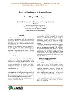
lenges of middleware and applications in DRE systems. Figure 1 illustrates CoSMIC’s MDD tools that address deployment and configuration lifecycle challenges of DRE systems. CoSMIC supports modeling of DRE system deployment and config����������������� ���������
���������
���������
���������
���������
����%,�
��������
� �����������
���������� �������� ���������
� �� �� � � � �% ,�
��������� �������� ���
� ����� �� ��� ��� ��� �� ��
���������
��$%��
�� �� ���� ��� ��
�������� ��������� �����������
�#���������������������
� �� �� ���
�%� �.$$�
�������� � ���.�
�� ��� � �� � ' �� ��� �� �� � ��� � �& ���� ���� �� ���
��������� ���������
��� ���
� �� ��� %, � �' �� �� %, �
���������
� �� ��� � ��� %, �!� �� ��
��������� ��������
���������
�" ��� �
���������
���������
���������� ��������
���������� ��������
��������
���������
��������� �������� ��������
��������� � � �����
�+�����������'� ����)�� ����
��������� ��� ��� ��� � � �
���� ��
���� ������
��������'�(/%,� ������ �����*�
� ��� ����
���������'�(���)�� ����
Fig. 1. The CoSMIC MDD Toolsuite
uration capabilities, their QoS requirements, and QoS adaptation policies used for DRE system QoS management. Its MDD tools are implemented via domain-specific modeling languages (DSMLs) developed using the Generic Modeling Environment (GME) [18], which is a configurable toolkit for creating domain-specific modeling and program synthesis environments. CoSMIC uses GME to define the modeling paradigms4 for each stage of its tool chain. CoSMIC ensures that the rules of construction – and the models constructed according to these rules – can evolve together over time. Each CoSMIC tool synthesizes XML-based metadata that is used by the CIAO QoS-enabled component middleware [4] described in Section 1. In particular, CoSMIC supports CIAO’s implementation of the OMG’s Deployment and Configuration (D&C) specification [19] and provides the following capabilities shown in Figure 1: • Specification and implementation, which enables application functionality specification, partitioning, and implementation as components. CoSMIC provides the Interface Definition Modeling Language (IDML), which is a DSML that can be used to specify component definitions. IDML also provides an importer that can transform preexisting IDL definitions into modeling elements. • Component assembly and packaging, which can bundle a suite of software binary modules and metadata representing application components. CoSMIC provides 4
A modeling paradigm defines the syntax and semantics of a DSML [11].
6
Gabriele Trombetti et. al.
the Platform Independent Component Modeling Language (PICML) [15], which is a DSML that models the connections between various components to form assemblies. PICML enables these assemblies to be composed into packages that can be shipped to target nodes. • Configuration, which allows packages to be customized with the appropriate parameters that satisfy the functional and systemic requirements of applications. CoSMIC provides the Options Configuration Modeling Language (OCML) [16] to model the middleware configuration rules, which are then synthesized into a rules engine and graphical environment that application developers use to configure the middleware. • Planning, which makes appropriate deployment decisions including identifying the entities, such as CPUs, of the target environment where the packages will be deployed. The Model Integrated Deployment and Configuration Environment for Composable Softwware Systems (MIDCESS) [13] DSML in CoSMIC can be used to model deployment plans for DRE system components. • Analysis and benchmarking, which enables run-time reconfiguration and resource management to maintain end-to-end QoS. CoSMIC provides the Benchmark Generation Modeling Language (BGML) [16], which models DRE systems QoS requirements and synthesizes empirical benchmarking testsuites. Additional analysis capability is achieved via integration with external tools, as described in Section 3. • Deployment, which triggers the installed binaries and brings the application to a ready state. CoSMIC is integrated with a run-time framework called DAnCE (Deployment and Configuration Engine), which implements the OMG’s D&C specification and can be used to model the deployment of DRE system packages according to precisely specified plans. The CoSMIC toolsuite also provides the capability to interwork with model checking tools, such as Cadena [14] (Section 2.2), and aspect model weavers, such as C-SAW [20]. The integration of CoSMIC with Cadena is the focus of Section 3. The core DSML provided by CoSMIC is PICML, which figures prominently in the integration of CoSMIC and Cadena described in Section 3. PICML allows developers to model packages of components into assemblies that can then be configured and deployed appropriately. Configuration and deployment concerns crosscut assemblies and systems. These crosscutting concerns are captured by the different aspects of PICML. During the configuration and deployment process, multiple concerns captured in the format of metadata in the component development process are woven together by PICML, as shown in Figure 2. PICML allows the specification of the component-based deployment and configuration concerns outlined above by allowing users to model them as elements in a GME paradigm. Additional constraints are defined via GME’s object constraint language (OCL) [21] facilities to ensure that the models built using PICML are semantically valid. PICML’s constraints check that the static semantics (i.e., the semantics that are required to be present at design time) are not violated. For example, at design-time, PICML can enforce the CCM constraint that only ports with the same interface or event type can be connected together.
MDD Environment for DRE Systems
7
Fig. 2. The PICML Architecture
The generative capabilities of PICML enable the separation of crosscutting deployment and configuration concerns, which are represented in the form of XML metadata and whose semantics can be validated automatically. The DAnCE run-time framework provided by CIAO is then responsible for weaving these concerns into component middleware and applications. The model interpreters in PICML target the configuration and deployment of DRE components for CIAO. We chose CIAO as our initial focus since it is QoS-enabled component middleware designed to meet the requirements of DRE systems. As other component middleware platforms (such as J2EE and .Net) mature and become suitable for DRE systems, we will (1) enhance CoSMIC so it supports platform-independent models (PIMs) and then (2) include the necessary patterns and policies to map these PIMs to platform-specific models (PSMs) for various component middleware platforms. 2.2 Overview of Cadena The Cadena [14] MDD toolsuite was built to investigate the effectiveness of a variety of structural and behavioral analysis techniques for component-based systems. It architectural slicing capabilities help developers identify dependencies among components for system understanding and for guiding component integration tasks, such as establishing event handling priorities and locking policies. Cadena’s behavioral descriptions and model checking capabilities enable developers to perform simple simulations of their systems to reason about, e.g., high-level mode transitions, and to check system designs against crucial system requirements phrased in the form of invariants, event/state ordering contraints and component interaction protocols phrased as regular expressions or temporal logic formulas. The following is a summary of the capabilities Cadena provides to develop component-based systems. •
A collection of lightweight specification forms that can be attached to IDL to specify mode variable domains, intra-component dependencies, and component
8
Gabriele Trombetti et. al.
state-transition semantics. These forms have a natural refinement order so that useful feedback can be obtained with little annotation effort, and increasing the precision of annotation yields more precise analysis. In addition, Cadena specifications allow developers to specify the same information in different ways, achieving a form of checkable redundancy that is useful for exposing design flaws. • Dependency analysis capabilities that allow tracing inter/intra-component event and data dependencies, as well as algorithms for synthesizing dependency-based real-time and distribution aspect information. • A novel model-checking infrastructure (based on the Bogor model-checking framework [22]) dedicated to event-based inter-component communication via real-time middleware enables system design models (derived from component IDL, component assembly descriptions and annotations) to be model-checked for global system properties. • A component assembly framework supporting a variety of visualization and programming tools for developing component connections. • A component deployment facility that auto-generates XML deployment and configuration information. • Cadena is implemented as a set of plug-ins to IBM’s Eclipse IDE, which enables the incorporation of other tools as add-ons to Cadena. In the integration with CoSMIC, we focus on using Cadena’s system configuration dependency analysis facilities. Even with small systems of ∼20-30 components, relationships between components and component dependences are often hard to determine from visual inspections of textual or graphical component assembly views. Component-based DRE system can often have over 1,000 components, and engineers at Boeing and Lockheed Martin with whom we collaborate have identified the development of automated support for component dependency analysis and visualization as a high priority. Given a component library and component assembly description (along with optional Cadena property specification file described below), Cadena’s dependency module builds a port dependence graph PDG = (N,E) where each node n ∈ N is a component/port pair (i.p). Edges (i.e., dependences) between PDG nodes arise from two sources: inter-component dependences corresponding to port connections specified in component assembly descriptions and intra-component dependences captured by CPS declarations in component property specifications. Cadena provides the following analysis capabilities for dependency graphs: • Forward and backward slices, which detects the components that are affected by (forward) or affect (backward) a particular component or port. Note that slices are computed at two levels of granularity: (1) a component-level forward slice finds all components that are affected by a given component vs. (2) a port-level forward slice finds all components that are affected by a particular port of a given component. In either case, slices are constructed by considering the reachability of components in the port dependence graph described above.
MDD Environment for DRE Systems
•
•
9
Chopping, which highlights all the ports and components that lie on a path between two given components/ports. Intuitively, given two components C1 and C2 , a chop based on C1 and C2 finds all paths between C1 and C2 by intersecting the forward slice from C1 and the backward slice from C2 . Cycle detection, which detects cycles along a series of event connections in the dependence graph. In certain computational models, event cycles may indicate design flaws.
Fig. 3. Cadena Dependency Analysis Interface
Figure 3 shows a portion of Cadena’s interface for issuing dependence-related queries over the graphical structure of a system configuration. The displayed pulldown menu allows developers to select from among the dependence analysis capabilities described above. The results of an analysis are displayed by changing the color of relevant components, ports, and connections. For example, the results of a forward slice are displayed by rendering in gray all the components, ports, and connections affected by the given component. Cadena decouples various aspects of modeling by requiring that these crosscutting concerns be captured in the following types of files located in a common project space: • IDL3 file *.idl, which contains OMG’s standard interface description language metadata describing components and their interfaces. • Scenario file (*.scenario), which describes an assembly of interconnected CCM components, including the value of their configuration properties. Cadena provides a graphical visualizer, a text editor, and a form view editor to manipulate
10
Gabriele Trombetti et. al.
*.scenario files. The equivalent of a scenario file in CoSMIC’s PICML is the CCM component assembly view, which enables graphical editing of properties. • Profile file (*.profile), which acts as a scenario format definition and validation system by defining the type of the properties that can be associated with different components and/or connections. Cadena supports three types for properties: STRING, INT, and BOOLEAN. There is no equivalent for the .profile file on PICML, which is another motivation for integrating CoSMIC and Cadena. • CPS (Cadena Property Specification) file (*.cps), which contains lightweight semantic annotations to capture abstract semantics that can be leveraged by Cadena’s analysis facilities. For example, in DRE systems, a component’s behavior is often organized into a collection of modes (e.g., a component can be in an active or inactive mode, or in a normal or fault-recovery mode, etc.). Modes can be used to represent the abstract state of a component. A component’s mode state is often implemented as a variable with an enumerated type that includes each of the mode states, and a modal component typically varies its behavior by branching to different implementations based on the current state of its mode variable. The *.cps file provides a means to capture the modes within a component and the internal interconnections within each component that depend on the mode. Information in this file includes conditional behavior, such as a set of inputs of a component having an effect on a set of outputs only when that component is in a particular mode/state. Cadena *.cps files can also include simple state transition systems – finite state automata that describe the abstract control flow of actions on a component’s interface (e.g., method calls and event publishing) as well as transitions on mode state variables. This information can be used to generate finite state models suitable for simulation or state-space exploration (model checking) of system designs. There is no equivalent for the *.cps file in PICML or in CCM.
3 Approaches to Integrating MDD Tools for DRE Systems Due to the magnitude and complexity of the DRE problem space, no single MDD toolsuite yet provides solutions to all challenges of large-scale DRE system development. For example, CoSMIC did not initially provide tools for analyzing and validating the functional correctness and QoS properties of DRE systems. Likewise, Cadena did not initially provide capabilities for modeling elements and procedures meaningful for important stages of the development of DRE systems, such as installation, packaging, and deployment. What we therefore required was an integrated MDD toolsuite that developers of DRE systems could use to compose, configure, and deploy their applications end-to-end to help (1) identify bugs early in the lifecycle, (2) reduce total development costs, (3) decrease time to market, and (4) increase the reliability of DRE systems. Integrating CoSMIC and Cadena required that (1) software components and associated modeling artifacts could be manipulated via any of their MDD tools, (2)
MDD Environment for DRE Systems
11
changes to the components and modeling artifacts made by one tool could be reflected in other tools, where applicable, (3) any tool capturing unique information (i.e., not captured by any other tool) required special support to preserve this information correctly, and (4) all the pieces of information captured by each integrated MDD tool could be treated as parts of a single global project. Achieving this level of integration was hard since different MDD tools captured different sets of properties. For example, certain CoSMIC tools captured certain parts of a project, whereas other parts are captured by certain Cadena tools.5 The remainder of this section describes key challenges that arose when integrating CoSMIC and Cadena and discusses our solutions to resolve these challenges. These challenges are discussed in order of increasing complexity, where a subsequent challenge could be resolved only when the previous challenge was addressed. Section 4 then presents a case study of a robot assembly application that illustrates our experiences applying the integrated CoSMIC and Cadena toolsuites to a representative DRE system. Challenge 1: Identifying an Inter-tool Communication Model Context. Different MDD tools provide different capabilities, e.g., browsable models and visual modeling of deploy requirements vs. rate-monotonic schedulability analysis and model-checking. Large-scale DRE systems, however, may require the use of multiple MDD tools. What is needed is a communication model for interoperability among various MDD tools. An important goal of our work was therefore to transfer model documents back and forth between CoSMIC and Cadena, while minimizing user intervention. Problems. Since Cosmic and Cadena were developed independently for several years they had little/nothing in common with respect to the type of model documents they used. Moreover, under many aspects these tools do not even capture the same type of information, e.g., the *.scenario and *.IDL3 model documents of Cadena appear to have equivalent representation in CoSMIC, but there are subtle differences between the model documents. Likewise, the *.profile, *.cor and *.cps model documents have no equivalent in CoSMIC. Similarly, 80% of the information in the CoSMIC model documents have no direct equivalent in Cadena. Many standard interoperability solutions available for tool interoperability cater to a specific concern. For example, the Analysis Interchange Format (AIF) [23] provides interoperability by promoting seamless exchange of only analysis data among tools. Similarly, the Hybrid Systems Interchange Format (HSIF) [24] provides model exchanges for those systems that are modeled as hybrid systems, but does not support exchanging analysis information. In many cases, therefore, an interchange format might not support a feature of a tool. Hence, a decision to use such an interchange format would preclude the use of that feature, thereby decreasing the value of the tool. It is also undesirable to create point-to-point solutions since they do not scale as the number of tools with different capabilities increases. It is therefore necessary to 5
The subset of the project captured by one tool is referred as the tool’s model document.
12
Gabriele Trombetti et. al.
develop a framework that allows seamless interoperability between desired features among tools without creating point-to-point solutions. Solution approach → An open tool integration framework. Our approach for integrating CoSMIC and Cadena is based on the Open Tool Integration Framework (OTIF) [25] developed by the Institute for Software Integrated Systems (ISIS) at Vanderbilt University. OTIF consists of a backplane, an integration repository, application-specific tool adapters, and semantic translators. The backplane provides a communication and subscription/notification mechanism for other tools. The backplane also acts as a common integration repository for the data stored in a canonical syntactical format, but which may have different semantics. OTIF’s tool integration repository stores data in a format understood by at least one of the communicating tools. Custom semantic translators and tool adaptors can then be plugged into the OTIF backplane and used to (1) automatically convert data in a format understood by one tool into of data for another tool and (2) communicate between the tools. A novel aspect of OTIF is its ability to integrate MDD tools that were not initially intended to interoperate, which is why we selected it for our CoSMIC↔Cadena integration. Figure 4 illustrates the interworking of CoSMIC and Cadena via the OTIF backplane. The OTIF backplane supports standard CORBA [26] communication ca-
Fig. 4. CoSMIC↔Cadena Interoperability via OTIF
pabilities using TAO [5], thereby allowing distributed interoperability, as well as platform-independent interoperability. Custom tool-specific adapters must be written by developers who wish to export desired tool-specific data to the backplane. Other tools that want to interoperate with this tool must provide an adapter that converts data on the backplane to the format it desires. We have developed appropriate tool adapters for CoSMIC and Cadena, along with semantic translators that help these two toolsuites interoperate via the OTIF backplane.
MDD Environment for DRE Systems
13
Challenge 2: Devising Effective Communication Protocols and Data Interchange Formats Context. An important concern for tool interoperability is ensuring that the tools understand each other’s data formats and their semantics. What is needed is a mechanism that allows exporting and importing tool-specific data using a tool integration framework, such as OTIF. Problems. There is often minimal overlap between tools, other than some common aspects pertaining to DRE systems. For example, the common information in CoSMIC and Cadena is restricted to the fact that both tools are tailored to support DRE systems build using the CORBA Component Model (CCM) [7]. These commonalities are localized in certain artifacts, such as the IDL descriptions and assembly information of CCM components. The same problem seen from another perspective is that when tools are integrated, they capture and contain in their model document two types of properties: (1) shared properties, i.e., properties being captured also by other tools being integrated and (2) unique properties, i.e., properties not captured by any of the other tools being integrated. Shared properties must often be transferred to other tools to synchronize the state amongst the tools. In contrast, unique properties cannot reasonably be transferred to another tool since they would not be understood. The distinction between shared and unique properties implies a separation of concerns that should be enforced by the two groups of tool properties. This, in turn, implies the following four problems: 1. The complexity of splitting properties in two groups (i.e., shared vs unique) 2. The task of transferring the shared group to remote tools 3. The choice of a common syntactical (not semantic) format for performing the communication and 4. The complexity of semantically merging the transferred information into the information already present in the destination tool. Problem 4 is the hardest since it requires the creation of semantic translators that can understand the formats of both tools to enable integration. Solution approach → Minimizing inter-tool information exchange. Problems 1 and 4 are interrelated (1 being easier to solve than 4). These were resolved together using semantic translators and a merging algorithm, as described in Challenge 3 below. We resolved problem 3 by identifying an information model based on XML for the data that is needed for the Cadena and CoSMIC tools. For example, CoSMIC generates information captured by the *.scenario model document in the form of XML descriptors and then creates a plug-in to import this XML format into Cadena. The reverse direction for this format incorporates the changes suggested by the Cadena analysis tools into the CoSMIC models. Problem 2 is more complex than problem 3, so we resolved it using OTIF, which allowed us to work at a significantly higher level of abstraction. For example, OTIF relieved us from many low-level details, such as the complexity of handling a communication among multiple tools. Each tool can be started and shut down at any
14
Gabriele Trombetti et. al.
time, can run in multiple instances, and might need to search for other tools and (re-)establish connections to them at any time. To function properly, OTIF requires support for document creation, persistence, and navigation to make data interchange seamless. OTIF thus supports a Universal Data Model (UDM) [27] interface to access and manipulate data on the OTIF backplane. UDM provides a development process and set of tools that generate C++ interfaces from data structures described using UML class diagrams. These interfaces and the underlying C++ libraries enable convenient programmatic access and automatically configured persistence services for data structures described via UML diagrams. We leverage these UDM capabilities for the data exchange between CoSMIC and Cadena. The modeling paradigms, such as CoSMIC’s PICML, built using GME were explicitly developed to expose a UDM interface. The Eclipse framework used by Cadena, however, does not support UDM natively, so we created a UML class diagram that described the Cadena models. Challenge 3: Achieving Lossless Semantic Transfers of Data Context. For any successful tool interoperability comprising data interchange, it is important that the exchanged data be transferred without loss of essential semantic information. Problems. Lossless semantic transfers of tool-specific data is hard since different tools address different aspects of DRE systems and therefore deal with different types of data, with their own semantics and representation. It is therefore possible (and common) for mismatches to arise between data supported by individual tools and how they are managed by the tool. For example, we outline the differences between CoSMIC and Cadena formats below: Cadena *.scenario files support properties on connections (such as event sources/sinks and invoke connections), whereas CoSMIC’s PICML does not. • Both PICML and Cadena support CCM connections types, such as emit, publish and invoke, but PICML provides specialized connector types for each of these in its CCM component assembly metamodel, whereas Cadena infers the connector types from the port types. • PICML supports QoS requirements on connections that are passed to the deployment run-time for validity checks and potential optimizations at deployment stage, whereas Cadena does not support this capability. • PICML provides a specialized connector for a publisher/subscriber connection involving multiple publishers and multiple receivers, whereas Cadena uses mulitple connections for this case. • Cadena supports the STRING, INT, and BOOLEAN attribute types, whereas PICML supports Boolean, Byte, ShortInteger, LongInteger, RealNumber, String, GenericObject, GenericValueObject, GenericValue, TypeEncoding, and TypeKind. •
MDD Environment for DRE Systems
15
Given these constraints, it is straightforward to create simple lossy export and import algorithms that would lose information not captured by one toolsuite vs. the other. This design, however, would force users to reenter information twice for each toolsuite, thereby increasing effort and the chance of inconsistencies in information maintained across the tools. What was desired, instead, is a write-once approach, whereby once information was entered using either CoSMIC or Cadena tools, the data transfer algorithm would preserve the data and its semantics for all but a few exceptionally rare circumstances. One approach to handle these issues is to merge the different data handled by individual tools to form a superset that is maintained by the OTIF backplane. Transferring the complete set of information between the tools is not maintainable, however, since whenever a feature should be added in any one of the tools being integrated, the set of information being transferred across all tools would change. At that point, all the semantic translators that convert documents from/to any two tools would need to be updated to support the enlarged information set. Solution approach → A graph-based diff-merge algorithm. Our solution uses information captured by individual MDD tools, focusing on the features that can map between the tools, and applying graph transformation algorithms to attain the desired interoperability. The information we transferred was contained in the CCM component assembly view of CoSMIC/PICML and in the *.scenario and *.profile files from Cadena, as well as the information conveyed in IDL3 files. In the transformation algorithm, the information from PICML is matched against the corresponding information in Cadena. Differences are detected and then depending on the direction of communication (PICML→Cadena or Cadena→PICML), such differences are imported into the destination tool, replacing earlier information that was outdated. This approach resembles a diff-merge algorithm (web.umr. edu/˜gnudoc/single/emacs1934/ediff.html), thought it is performed on data from MDD tools that were stored as a graph of interconnected information rather than sequential text. We therefore call our approach a graph diff-merge algorithm. The graph diff-merge algorithm for exporting PICML data to Cadena follows the steps described below (Sidebar 1 explains the CCM terminology used in these steps). 1. Every CCM component assembly generates a separate *.scenario file. The full path name of the assembly from the RootFolder is encapsulated in a property called PICML pathname, which is stored by Cadena and eventually returned to PICML unchanged. This property is needed to match the same source CCM component assembly on the PICML side when reimporting. 2. CCM component assembly-level properties are transferred to Cadena as scenariolevel properties if the type is supported by Cadena, otherwise they are retained on the PICML side. 3. All the PublishConnectors are checked and the newly created ones are flagged with a unique ConnectorID, which is in a DeployRequirement having a magic name that is disregarded by the DAnCE D&C run-time system provided by CIAO.
16
Gabriele Trombetti et. al.
Sidebar 1: CCM as Captured in CoSMIC and Cadena This sidebar explains key CCM concepts and terminology, and then shows how they are supported by CoSMIC and Cadena when diverging from each other or from the CCM specifications. CCM components model units of software and contain ports for communicating with other components. Ports are divided into (1) asynchronous event-based ports (EventSources and EventSinks) and (2) synchronous operation-based ports (Facets and Receptacles), which can be connected together with Invoke connections (for operation-based ports) and Emit or Publish connections (for event-based ports). Publish connections originating from an EventSource need to pass through a PublishConnector element in PICML before reaching any EventSink port, whereas Cadena has no concept of PublishConnector. Emit connections can only connect one EventSource to one EventSink, while Publish connections can be many-to-many. The explicit distinction between Publish and Emit connections, however, only exists in PICML, whereas in Cadena both are mapped to a generic EventSource-to-Sink connection. Properties are name/type/value triplets that can belong to Components or to Requirements in PICML, whereas in Cadena they can belong to Components and to Connections between ports. Requirements (a.k.a. Deploy Requirements, PICML only) are contained in Components and PublishConnectors and serve to hold constraints (defined as a set of Properties) specifying where a Component or PublishConnector can be deployed. An Assembly (PICML only) holds Components, connections between their ports, PublishConnectors, Requirements associated to Components or PublishConnectors, and Properties associated to Components. The correspondent of an Assembly in Cadena is the Scenario, which contains Components, Connections between their ports, and Properties associated to these Components and Connections. In PICML and Cadena there can be multiple Assemblies/Scenarios distinguished by a different path from a so-called RootFolder.
4. All PublishConnectors are checked for the presence of a Requirement with another magic name called CadenaProperties. If found, all the properties encapsulated inside such a requirement are output as properties on the EventSourceto-Sink corresponding connection in Cadena, which compensates for the lack of properties on connectors on the PICML side. 5. All Components that have an output Emit or an Invocation connection are checked for a property with a magic name: CadenaEIProperties (where EI stands for “Emit-Invoke”). This property contains a string that is the dump of an XML file containing multiple properties for each Receptacle-to-Facet or Event Source-to-Sink Emit connection output from that component. The embedded file is parsed and the contained information is extracted and sent to Cadena, which accounts for the lack of properties on emit and invoke connections on the PICML side.
MDD Environment for DRE Systems
17
6. All component instances are browsed and their name and type are transferred to Cadena. The attached properties are transferred to Cadena only if they are a type supported by Cadena, otherwise they are retained on the PICML side. For all components, each connection to a remote port or to a PublishConnector is passed to Cadena. At this point, the XML file containing the information about the scenario (and implicitly about the profile) is sent to the OTIF backplane. On the Cadena side it is fetched, de-encapsulated from XML, and dumped to disk, possibly overwriting a preexisting version. During Cadena export to PICML, the transfer across the OTIF backplane acts in the reverse way. The key points of the graph diff-merge algorithm on the PICML side are as follows: 1. Using the PICML pathname information, the same CCM component assembly of the export is matched so that the modifications can be performed in the correct place. 2. Based on the names of the component instance, the components are matched. 3. Based on the ConnectorIDs, the PublishConnectors are matched. On the PICML side, the components and the PublishConnectors that have no match on the Cadena side are considered deleted by the Cadena user and thus get destroyed on the PICML side. The properties and requirement that only refer to those are also destroyed. 4. The Components and PublishConnectors on the Cadena side that are unmatched on the PICML side are considered newly created and thus created on the PICML side. 5. All the emit and invoke connections at the PICML side are deleted, and are recreated new from the information on the Cadena side. 6. All the properties on PICML components and at the component assembly-level are browsed. For those where the type could have been passed to the Cadena side, a match to the properties on the Cadena side is attempted. If the match fails, those PICML properties are considered to be deleted by the Cadena user, so they are destroyed on the PICML side. 7. For all properties on Components on the Cadena side, a match is attempted on the PICML side. If the match succeeds, the value is updated on the PICML side, otherwise this is considered a new property created by the Cadena user so a new property gets created on the PICML side. 8. Steps 7 and 8 are repeated again for properties on PublishConnectors, with the difference that the match is attempted inside the Requirement called CadenaProperties, if it exists. The newly created properties are also created there (if a requirement with such a name does not exist, it is created and attached to the PublishConnector). 9. Steps 7 and 8 are also repeated again for the properties on EmitConnector and PublishConnector, but this time the match is attempted on the XML content of the magic property CadenaEIProperties on the component that has the outgoing emit or invoke connection, which is created if needed.
18
Gabriele Trombetti et. al.
To perform these steps for the two directions of communication, we used the GReAT (Graph Rewriting And Transformation) [28] tool. GReAT is a GME-based MDD tool that can be used to visually define graph transformation among networks of objects that are accessible with UDM. GReAT shortened our development time significantly since it is much more readable and maintainable than using a thirdgeneration programming language, such as C++ or Java. Both GME project files and XML files whose schema can be defined with an UML diagram can be accessed via UDM. A GReAT transformation can be run interpretatively during development and debugging. It can also be used to generate C++ header and implementation files that can be compiled for a release version of the transformation. The current version of the CoSMIC↔Cadena import/export transformation contains more than 2,000 elements (graph pattern nodes) and 13,500 lines of C++ code. Figure 4 illustrates the architecture of this transformation process, where a bidirectional GReAT-based tool adapter and semantic translator converts PICML assemblies to/from XML files conforming to the adopted interchange schema, which was chosen to conform to the semantics of Cadena *.scenario and *.profile files. The schema, known to the OTIF backplane, is used to read and validate the XML file upon arrival on the backplane. At every upload of a new interchange XML file onto the backplane, the tool adapters are notified of the availability of such new CCM component assembly and are prompted for the download. On the Cadena side, a simpler Java-based Cadena tool adapter converts the XML to *.scenario and *.profile files and vice versa. Our graph diff-merge algorithm is activated during the backplane-to-PICML import and is implemented inside the GReAT-based PICML tool adapter and semantic translator.
4 Demonstrating Integrated CoSMIC↔Cadena Capabilities via a Robot Assembly Case Study This section describes a case study of a robot assembly application we developed in conjunction with colleagues at Lockheed Martin. This application is representative of DRE systems in the process control domain, i.e., it defines an assembly line with robots creating various types of goods, which in our case study are wrist watches assembled by robots. We describe the robot assembly application below to illustrate the benefits of integrating and applying the CoSMIC and Cadena MDD toolsuites, as described in Sections 2 and 3. In particular, this case study illustrates how developers of the robot assembly application required multiple MDD tools, each providing different capabilities, such as configuration, deployment, schedulability analysis, and model checking. The source code and integrated MDD tools for this example are available in the CIAO release from www.dre.vanderbilt.edu/CIAO.
MDD Environment for DRE Systems
19
4.1 Structure and Functionality of the Robot Assembly Application Figure 5 illustrates the five core components in the robot assembly application: ManagementWorkInstruction, WatchSettingManager, HumanMachineInterface, PalletConveyorManager, and RobotManager, each of ���� ��
�� � ��������� ���� ���� ���� ������
�����
��������� %����
���� � �
��� �
� � ��
������ � "�� #��!�
����� ������ ��� ����
"�� #��!� $���
����� � ����� ����� �
��� � ���� �� ����� �
��� � � � �� ������ %�� �!�
%� � ���������
������� ������� ��� ������
���� �� ���� � �� �
������ ��� �������� �
��!�� ����� �
��!�� �� ���� %� �
����� ����� �
Fig. 5. Robot Assembly Model
which are implemented as CCM components using CIAO. These individual CCM components can be interconnected together to form CCM component assemblies and ultimately deployed using DAnCE to create complete applications. Figure 6 depicts a sequence diagram for the robot assembly production process. The ManagementWorkInstruction and HumanMachineInterface components interact with humans, whereas the PalletConveyorManager and RobotManager components interact with the pallet moving and assembling tools hardware devices, respectively. The normal operation of the robot assembly application involves the following steps: 1. The ManagementWorkInstruction asks for a watch to be produced by sending an event to the WatchSettingManager. 2. The WatchSettingManager emits an event to the HumanMachineInterface asking to validate the order. The HumanMachineInterface accepts the order by invoking an operation on a CCM facet belonging to the WatchSettingManager. 3. The WatchSettingManager uses a different event to notify the ManagementWorkInstruction that the order was accepted and then displays the work on the HumanMachineInterface.
20
Gabriele Trombetti et. al.
Watch Setting Manager
Human Machine Interface
WSM
HMI
Management Work Instructions
MWI
Production work Order
Display work order Production order accepted
keyboard
Pallet Conveyer Manager
PCM
Discrete
Robot Manager
RM
Robot
Accept key
Accept work order Display work update Pallet in position
Move pallet to work area Pallet ready Display ready to produce
Produce key
Proceed Process pallet Pallet complete Display processing complete Processing accepted
Accept key
Release pallet
Move pallet to finishing area Pallet moved Work order complete
Pallet not in position
Fig. 6. Robot Assembly Production Sequence
4. The WatchSettingManager emits an event to the PalletConveyorManager to move the pallet into position. The PalletConveyorManager then responds with another event acknowledging the status of good positioning on the pallet. This event includes an enumerated type indicating status, such as acceptance, rejection, completion, failure, and/or cancellation. 5. The WatchSettingManager again emits an event to the HumanMachineInterface asking for confirmation to perform a production step. The HumanMachineInterface accepts by invoking an operation on a facet. 6. The WatchSettingManager emits an event to the RobotManager asking it to process the pallet. The RobotManager performs the job and then responds via an event acknowledging the success (or failure) of the assembling operation. 7. The WatchSettingManager displays the completed work to HumanMachineInterface via an event. The HumanMachineInterface validates the work via a facet operation call (same as in bullet 1). 8. The WatchSettingManager sends an event asking the PalletConveyorManager to move the pallet out of the working area and into a finishing area. The PalletConveyorManager notifies the status of the operation back to the WatchSettingManager with the acknowledgment event already discussed. Steps 2-7 can be repeated if there are additional pallets to process. 9. The WatchSettingManager sends an event to the ManagementWorkInstruction notifying it that the requested job has been completed.
MDD Environment for DRE Systems
21
4.2 Key Capabilities Provided by CoSMIC and Cadena Integration for the Robot Assembly Application Section 4.1 described the structure and functionality of the robot assembly application. We now illustrate the key challenges encountered when integrating the CoSMIC and Cadena MDD toolsuites and applying them to the robot assembly case study. Capability 1: Choosing appropriate communication mechanisms. Developers of large-scale component-based DRE systems must determine which communication mechanisms their components should use to interact. A key design decision is whether to use CCM facets and receptacles, which can perform pointto-point synchronous operation invocations between components, or event sources and sinks, which can exchange typed messages asynchronously with one or more components. Applying an MDD tool like PICML (Section 2.1) can help developers reason more effectively about which communication mechanism to select. Below, we demonstrate how our MDD tools help developers make better design choices.
Fig. 7. Robot Assembly CCM Component Assembly Visio Drawing
Figure 7 shows a Visio drawing of the robot assembly component interaction. We used this informal drawing to guide our subsequent formal modeling and analysis of the robot assembly application. In particular, we created a model of the CCM component assembly in PICML and then used Cadena to analye, validate, and refine this model. After validation by Cadena, we used the CoSMIC toolsuite to deploy, configure and run the robot assembly application. Figure 8 (without the connection pointed by the arrow) represents the PICML model that captures the application represented by the Visio drawing in Figure 7.
22
Gabriele Trombetti et. al.
Fig. 8. Erroneous Robot Assembly PICML Model
Unlike the informal Visio drawing, the PICML model is semantically navigable, down to the data types and events exchanged by every operation and event communication. By inspecting the PICML model, we can quickly spot design fallacies and/or vulnerabilities, e.g., the return value of the facet invocation for the response of HumanMachineInterface to WatchSettingManager (Section 4.1) is void and there are no out or inout parameters, yet the operation is not defined as a CORBA oneway. Further analysis indicates that a more appropriate choice for this communication would be an asynchronous connection (event) rather than a facet/receptacle. This analysis thus reveals a design mistake made by the developers at the components (IDL) modeling stage. Such mistakes are less common when working with visual modeling environments due to the visual feedback developers receive continuously. There is still a possibility of errors due to the fact that at component (IDL) modeling stage the view of the CCM component assembly providing the “big picture” is not yet available. At the time the component assembly is also modeled, however, the presence of a navigable visual model significantly helps developers spot such problems, compared with reading hundreds of lines of CORBA IDL code. In addition, refinement cycles for correcting such errors in the IDL and then adjusting the component assembly accordingly are much faster to perform with a visual modeler than when dealing with low-level source code. Capability 2: Detecting type mismatches at design-time vs. run-time. As mentioned in Section 1, a key goal of MDD is achieving “correct by construction” programs. In particular, MDD tools should allow only correct choices and/or detect maximum number of errors at design-time rather than run-time. Constraining a correct choice or performing an early detection of mistakes significantly reduces the time needed for fixes. To evaluate how effectively our integrated CoSMIC and Cadena tools described in Section 3 work in the context of our robot assembly application, we deliberately tried to introduce a mistake in our component assembly by connecting an additional port to a destination port of the wrong type. This mistake is detected by PICML’s
MDD Environment for DRE Systems
23
constraint checker because the two ends are not of the same type, and thus disallowed by the PICML paradigm. It would not be desirable, however, to have trivial human mistakes detected by only one tool (e.g., PICML), as this would defer the detection significantly when users work for long period of time on other tool(s) (e.g., Cadena) before going back to PICML. Cadena (described in Section 2.2) also immediately detects a set of potential human mistakes, including connections with mismatched endpoints and mismatched type for properties on components. These checks are performed both at modeling time and model-import time and can be verified, e.g., by importing into Cadena an erroneous model produced by a tool that has weaker validation support. In our case, PICML is (currently) the only other tool, so testing this feature required manually disabling PICML’s constraint checker, manual creation of an invalid connection, and then exporting the result to Cadena. For this example, we chose to connect the analysis receptacle of the WatchSettingManager to the controller facet of PalletConveyorManager, as shown in Figure 8 with a block arrow. Figure 9 shows how Cadena detected the wrong connection, and printed an error message. Early (possibly immediate) detection of user mistakes, even when limited to simple ones, is important since it reduces the work that must be undone to roll back to a valid project state when a mistake is detected.
Fig. 9. Error Detected by Robot Assembly Cadena Model
24
Gabriele Trombetti et. al.
Capability 3: Advanced model checking of component assemblies. Another important capability provided by MDD tools is advanced model checking, such as Cadena’s feature that detects cyclic call chains and event feedbacks and can be used to reason about the possible deadlocks that may occur in a concurrent system. Since all robot assembly components only interact with the WatchSettingManager, any possible cycle must pass through that component. Right clicking the WatchSettingManager component in the graphical scenario view of Cadena and selecting the “cycle check” feature highlights two components of the assembly – the HumanMachineInterface and the WatchSettingManager – which form a cycle, as shown in Figure 10. The cycle detection stops after the first detection,
Fig. 10. Robot Assembly Modeless Cycle Detection in Cadena
which is why only two components are highlighted (darker colors) in the figure. If we disconnect those two components and repeat the cycle check, however, other components will be highlighted. The WatchSettingManager affects and is affected by every other component, so eventually every component is in the downstream path of every other component in the component assembly. Since we have at least one cycle we cannot be certain that deadlocks do not occur. Deadlocks for such a model are thus “implementation defined,” which means that they might or might not be avoided with a more sophisticated implementation,
MDD Environment for DRE Systems
25
e.g., one that handles assumptions that cannot be (or are not) modeled. The system therefore cannot be validated from a modeling perspective. Examining the production sequence diagram in Figure 6 above, however, clearly shows that no deadlock can occur, at least during the normal production use case. This information clashes with the analysis from Cadena, due to the fact that we have not yet specified modal information in our components, i.e., component operational modes specifying interactions between input and output ports of the same component (intra-component interactions). Specifying modal information allows a more precise detection of cycles and potential deadlocks. For the semantics shown in Figure 6’s production sequence diagram, most components can remain stateless. At least two components require state, however, the WatchSettingManager and the HumanMachineInterface. For the WatchSettingManager, the sequence diagram in Figure 6 implicitly defines the following seven states: (1) WaitingWorkOrder, (2) WaitingAcceptWorkOrder, (3) WaitingPalletReady, (4) WaitingProceed, (5) WaitingPalletComplete, (6) WaitingPalletMoved, and (7) WaitingProcessingAccepted. In each state, no more than one input port affects an output port, and not all the output ports are affected (in facts, no more than three are affected for each mode). The other input and output ports behave as if they were disconnected. For the HumanMachineInterface, we need to specify that a DisplayWorkUpdate cannot trigger an AcceptWorkOrder. Otherwise, a feedback cycle with the WatchSettingManager will arise. At least two states are needed, though it is better to specify all four semantically detectable states: (1) WaitingNewWorkOrder, (2) WaitingDisplayWorkUpdate, (3) WaitingReadyToProduce, and (4) WaitingDisplayProcessingComplete. The behaviors of the WatchSettingManager and the HumanMachineInterface components outlined above can be captured in the Cadena property specification (*.cps) file shown below: module RobotAssembly { component WatchSettingManager { mode status of { WaitingWorkOrder, WaitingAcceptWorkOrder, WaitingPalletReady, WaitingProceed, WaitingPalletComplete, WaitingPalletMoved, WaitingProcessingAccepted } init status.WaitingWorkOrder; dependencydefault: none; dependencies { case status of { WaitingWorkOrder: WorkOrder -> Display; WaitingAcceptWorkOrder: DisplayResponse.WorkOrderResponse -> MovePallet, Display,
26
Gabriele Trombetti et. al.
}
}
}
ProductionReport; WaitingPalletReady: PalletStatus -> ProductionReport; WaitingProceed: DisplayResponse.ProductionReport -> MovePallet; WaitingPalletComplete: ProcessingStatus -> MovePallet; WaitingPalletMoved: PalletStatus -> Display; WaitingProcessingAccepted: DisplayResponse.ProductionReadyResponse -> ProductionReport, MovePallet;
} component HumanMachineInterface { mode status of { WaitingNewWorkOrder, WaitingDisplayWorkUpdate, WaitingReadyToProduce, WaitingDisplayProcessingComplete } init status.WaitingNewWorkOrder; dependencydefault: none; dependencies { case status of { WaitingNewWorkOrder: WorkDisplayUpdate -> HumanResponse.WorkOrderResponse; WaitingDisplayWorkUpdate: WorkDisplayUpdate -> ; WaitingReadyToProduce: WorkDisplayUpdate -> HumanResponse.ProductionReadyResponse; WaitingDisplayProcessingComplete: WorkDisplayUpdate -> HumanResponse.PalletInspectionResponse; } } }
The Cadena *.cps file shown above sets our modal specifications for the robot assembly project. The remainder of this section refers to the modal view of the scenario illustrated in Figure 11. The two components for which we have defined the states must be set to a globally consistent state, i.e., we cannot set the WatchSettingManager in the WaitingPalletComplete state while the HumanMachineInterface is in the WaitingNewWorkOrder state. We therefore set the WatchSettingManager in the WaitingAcceptWorkOrder state and the HumanMachineInterface in the WaitingDisplayWorkUpdate state. As a result, only the connections that belong to the current mode will be shown (see
MDD Environment for DRE Systems
27
Fig. 11. Robot Assembly: Modal View in Cadena
Figure 11). Since the cycle analysis will detect any cycles in any of the modes, the current model can be analyzed to detect deadlocks. For contrast, we also show a variation of the robot assembly CCM component assembly that is in fact not deadlock-proof and hence cannot be validated. This variation consists of adding the connection from the WatchSettingManger/Analysis receptacle to the RobotManager/Analysis facet. 6 We do not have any semantic or behavioral specifications for these analysis ports. We must therefore assume that (1) operation calls on the facets can affect any analysis receptacle on the same component and (2) this behavior can happen in any mode of the three components. To reflect this scenario we add the following lines for the WatchSettingManager into the *.cps file shown below: ... dependencies { AnalysisOne.CallingBackTwo -> Analysis.CicrleCallOne, Analysis.CallingBackOne; AnalysisTwo.CircleCallThree -> Analysis.CicrleCallOne, Analysis.CallingBackOne; case status of ... } 6
Figure 7 shows that the following two CCM ports were already connected: (1) RobotManager/CircleAnalysis receptacle to PalletConveyorManager/CircleAnalysis facet and (2) PalletConveyorManager/AnalysisTwo receptacle to WatchSettingManager/AnalysisTwo facet.
28
Gabriele Trombetti et. al.
The resulting scenario shows a cycle (illustrated in Figure 12) in at least one mode (and in this particular case, in all the modes). Armed with this knowledge,
Fig. 12. Robot Assembly: Cadena Model After Circle Analysis
therefore, any deadlock avoidance must be at the implementation level, i.e., this model cannot be validated against deadlocks without further knowledge of the semantics at the modal level. 4.3 Summary of the Robot Assembly Case Study This section used a robot assembly application case study we developed with our colleagues at Lockheed Martin to showcase our integration of CoSMIC and Cadena. The case study shows how semantic validation of models can help detect problems earlier in the software lifecycle, e.g., immediately after the planning of the interfaces, but before implementing the business logic. In our experience, early detection of defects yielded fewer code revisions, lower development costs, and shorter time to market. This “correct by construction” paradigm and the ongoing checking for human mistakes made by CoSMIC and Cadena helped ensure proper execution in mission-critical contexts, where run-time error-detection and debugging alone was insufficient. In particular, the CoSMIC PICML MDD tool helped developers formally define CCM component assemblies, while allowing better visualization and easier navigation that can be useful to improve design, spot errors more easily, and in general work at a higher level of abstraction and be more productive. The Cadena environment, likewise, provided powerful analysis and validation features, which were synergistic with those of PICML. In Cadena, a relatively straightforward declarative
MDD Environment for DRE Systems
29
language was used to define high-level behavioral specifications for components. These specifications were then used for analysis and validation purposes, such as component-dependencies traversal and ensuring the robot assembly application was free of deadlocks.
5 Related Work Model-driven development (MDD) technologies are used in a variety of contexts and domains. For example, the OMG’s Model Driven Architecture (MDA) [29] and Microsoft’s Software Factories [12] focus mainly on enterprise business applications. Other MDD technologies, such as Model-Integrated Computing (MIC) [30], focus on embedded systems. More recently, MDD technologies are aligning [31] to add QoS capabilities necessary to support DRE systems in domains ranging from aerospace [32] to telecommunications [33] and industrial process control [34]. This section describes compares our research on MDD technologies with related work. Our work on MDD technologies extends earlier work on MIC [11, 35, 36, 37] that focused on modeling and synthesizing embedded software. Examples of MIC technology used today include GME [18] and Ptolemy [38] (used primarily in the real-time and embedded domain) and MDA [10] based on UML [39] and XML [40] (which have been used primarily in the business domain). Previous efforts using MIC technologies for QoS adaptation have been applied to embedded systems comprising digital signal processors or signal detection systems [41, 42], which have a small number of fairly static QoS requirements. In contrast, our research on integrating CoSMIC and Cadena focuses on enhancing and applying MIC technologies at a much broader level, i.e., modeling and controlling much larger scale DRE systems with multi-dimensional simultaneous QoS requirements. Other related MDD tools are the Virginia Embedded System Toolkit (VEST) [43] and Automatic Integration of Reusable Embedded Systems (AIRES) [44]. VEST is an embedded system composition tool based on GME [18] that (1) enables the composition of reliable and configurable systems from COTS component libraries and (2) checks whether certain real-time, memory, power, and cost constraints of real-time and embedded applications are satisfied. AIRES provides the means to map design time models of component composition with real-time requirements to run-time models weaving timing and scheduling attributes within the run-time models. Although VEST and AIRES provide modeling and analysis tools for real-time scheduling and resource usage, they have not been applied to QoS-enabled component middleware, which is characterized by complex interactions between components, their containers and the provisioned services, and across distributed components via real-time event communication or request/response. Moreover, our research on the integration of CoSMIC and Cadena involves whole-system global analysis of large-scale DRE system for end-to-end timing constraints, as well as configuration and deployment. Another project aimed at tool integration is the Open Tool Integration Framework (OTIF) [25], which was developed by the Institute for Software Integrated
30
Gabriele Trombetti et. al.
Systems (ISIS) at Vanderbilt University. As opposed to our approach – where most features of Cadena and CoSMIC were developed separately and with no initial idea of subsequent integration – OTIF explicitly provides a framework for integrating tools developed as part of the DARPA MoBIES project [24]. The MoBIES workflows are fairly complex and allow interoperations in multiple directions among the tools. These flows are not lossless in most cases, however, so they were able to obtain seamless round-trip interoperability in only one case, i.e., between the ESML and OEP Configuration formats, inside the ESML workflow. OTIF provides a communication framework with facilities for storing various versions of the same set of data written in different formats, subscription/notify mechanism, and automatic triggering of application-specific translators when certain data format are submitted to the backplane (data repository). OTIF requires, however, that the actual (application-specific) semantic translators and the (applicationspecific) tool adapters for actually performing the communication and the translation be provided by the user. Our work with CoSMIC and Cadena helps improve upon earlier uses of OTIF by selecting interchange formats and transformation semantics that can accomplish more effective round-trip interoperability and lossless communication between the two MDD development environments.
6 Concluding Remarks Model-driven development (MDD) of software engineering processes is emerging as an effective paradigm for addressing the challenges of distributed real-time and embedded (DRE) systems. MDD is a software development paradigm that systematically applies domain-specific modeling languages to engineer computing systems. It is therefore a key step towards converting the art of programming into an engineering process that will industrialize the software industry. This chapter showed how we have integrated (1) CoSMIC, which is an MDD toolsuite consisting of modeling, analysis, and synthesis tools that address key lifecycle challenges of component-based DRE systems with (2) Cadena, which is an MDD toolsuite for modeling and model checking component-based DRE systems. We demonstrated how CoSMIC can leveraged Cadena/Bogor’s model checking and verification capabilities to raise the reliability of component-based DRE systems significantly, while also reducing development time and effort. We also showed how the capabilities provided by CoSMIC and Cadena are complementary and can help developers of component-based DRE system middleware and applications view and analyze models from different perspectives. The novelty of our approach focuses on exchanging a minimal set of data between interacting tools, namely the common subset of properties captured by the tools. Modifications on a project made by CoSMIC tools can thus be transferred to Cadena tools and merged into the model document of the destination tools and vice versa. Modifications performed on properties captured uniquely by CoSMIC tools need not be transferred to Cadena tools and vice versa. Depending on the tools being
MDD Environment for DRE Systems
31
integrated, the merging of modifications into a tool’s model document can be performed automatically by semantic translators (which keep state in this case) or tool adapters (which can access the internal state of the tool). In either case, our general approach can greatly simplify the integration of various external MDD tools, e.g., to provide model checking, schedulability, and stability analysis. Section 3 describes a graph diff-merge algorithm that transfers modifications into a destination tool’s model document and semantic translators that convert between the formats understood by various CoSMIC and Cadena MDD tools. Graph transformation is used to define algorithms for semantic translation and merging directly at the metamodel level, i.e., at a higher level of abstraction than provided by thirdgeneration programming languages. This approach (1) reduces the time needed to develop semantic translators, compared with manually writing a backtracking engine to match entire graphs, (2) reduces sporadic and hard-to-track errors that stem from manually manipulating pointers, allocate resources, and handling exceptions, and (3) increases the readability and maintainability of the algorithms, compared with conventional hand-written code in third-generation languages. The lessons learned by applying our integrated CoSMIC and Cadena toolsuite to the robot assembly case study described in Section 4 illustrated that: Not every MDD tool offers the same capabilities, but a collection of these is needed to develop DRE systems, which is why interoperability between the tools is necessary. For example, CoSMIC and Cadena have different modeling capabilities and validation functionalities that we combined to provide a broader range of capabilities for DRE system developers. • Although partial, user-assisted interoperability is easier to realize, it does not prevent human mistakes when exporting model documents from one tool and importing them into another. It is therefore essential to automate the communication process as much as possible to ensure consistency. For example, our use of the Open Tool Integration Framework (OTIF) [25] helped minimize the number of steps needed for users to transfer the robot assembly project between the CoSMIC and Cadena tools. We also carefully crafted the graph diff-merge algorithm to avoid manual replication of information. • Bidirectional communication among MDD tools is the most effective way to enable users to edit models locally on whichever tool is in use, while maintaining the ability to transfer changes to other tools automatically, thus enhancing consistency. For example, when developing the communication between CoSMIC and Cadena, we allowed developers to use the tools in any semantically valid order, and did not constrain the actions that could be performed while working with any compatible tools. • When achieving tool integration, key issues to consider are the communication model, data interchange format, and algorithms for lossless data transforms. Our CoSMIC↔Cadena integration focused on these three points and applied tools that could help reduce our development time. For example, we used OTIF to provide communication features, document storage on the backplane, and automatic notification of availability of new documents to connected tools. We used •
32
Gabriele Trombetti et. al.
XML/UDM to interchange the syntactic and semantic formats of CoSMIC and Cadena model documents. We used GReAT for our graph diff-merge algorithms to reduce development time and detect/merge variations of graph-based data formats. These tools allowed us to complete our robot assembly development and validation tasks correctly in a relatively short time. • Complex transformation algorithms become more manageable when working at the meta-level. In particular, several hundred well-structured graphical transformation rules are faster to write and easier to read and maintain than thousands of lines of equivalent C++ code. For example, we leveraged the GReAT tool to graphically define graph transformations. • To define transformations at the meta level requires access to the metamodels (represented as graph structures) of both the source and destination semantic formats. If any of such metamodels are not available, an alternative is to use an XML format defined with a UML diagram (i.e., the metamodel) acting as a proxy for the source or destination format. For example, the metamodel of Cadena internal document format was not available, so we used GME to define an XML representation of it in UML. We could then use GReAT to define transformations between the CoSMIC metamodel and the newly defined XML format, the latter acting as a proxy for Cadena format. • The message flow in our robot assembly case study is largely asynchronous and most communication is performed via events, though some callbacks are performed via invocations on facet operations. It is hard to recognize this message flow from the production sequence diagram in Figure 6, but MDD tools, such as PICML in CoSMIC and the Cadena’s Scenario graphical view, can show which communications are performed through event emissions and which are invocation on operations. MDD tools also enable more efficient browsing through components and interfaces to indicate visually which data types are exchanged. • Behavioral specifications of components can be used to perform dependency checks and stability analysis in a component-based distributed application. Underspecifying the behavior of such components might prevent a complete validation, as happened with the connection of circle analysis port in our robot assembly application. • When solving new problems, the time needed to learn new MDD tools appropriate for the solution must be considered. For example, we used GME interpreters, GReAT, UDM, and OTIF for our robot assembly application. Acquiring expertise with these tools occupied roughly one third of the total development time. It is therefore essential to factor the time and effort needed to learn multiple MDDs tools to avoid underestimating overall development costs.
Acknowledgments The authors would like to acknowledge our collaborators Sylvester Fernandez, Dave Bailey, Chris Andrews, Bob Parkhill, and Theckla Louchios from Lockheed Martin, Eagan and Dallas for their help with the CoSMIC↔Cadena integration.
MDD Environment for DRE Systems
33
References 1. Wendy Roll, “Towards Model-Based and CCM-Based Applications for Real-Time Systems,” in Proceedings of the International Symposium on Object-Oriented Real-time Distributed Computing (ISORC), Hakodate, Hokkaido, Japan, May 2003, IEEE/IFIP. 2. David C. Sharp and Wendy C. Roll, “Model-Based Integration of Reusable Component-Based Avionics System,” in Proceedings of the Workshop on Model-Driven Embedded Systems in RTAS 2003, May 2003. 3. Richard E. Schantz and Douglas C. Schmidt, “Middleware for Distributed Systems: Evolving the Common Structure for Network-centric Applications,” in Encyclopedia of Software Engineering, John Marciniak and George Telecki, Eds. Wiley & Sons, New York, 2002. 4. Nanbor Wang, Douglas C. Schmidt, Aniruddha Gokhale, Craig Rodrigues, Balachandran Natarajan, Joseph P. Loyall, Richard E. Schantz, and Christopher D. Gill, “QoS-enabled Middleware,” in Middleware for Communications, Qusay Mahmoud, Ed. Wiley and Sons, New York, 2003. 5. Douglas C. Schmidt, David L. Levine, and Sumedh Mungee, “The Design and Performance of Real-Time Object Request Brokers,” Computer Communications, vol. 21, no. 4, pp. 294–324, Apr. 1998. 6. Object Management Group, Real-Time CORBA Specification, 1.1 edition, Aug. 2002. 7. Object Management Group, CORBA Components, OMG Document formal/2002-06-65 edition, June 2002. 8. Nanbor Wang and Christopher Gill, “Improving Real-Time System Configuration via a QoS-aware CORBA Component Model,” in Hawaii International Conference on System Sciences, Software Technology Track, Distributed Object and Component-based Software Systems Minitrack, HICSS 2003, Honolulu, HW, Jan. 2003, HICSS. 9. Nanbor Wang, Chris Gill, Douglas C. Schmidt, and Venkita Subramonian, “Configuring Real-time Aspects in Component Middleware,” in Proceedings of the International Symposium on Distributed Objects and Applications (DOA’04), Agia Napa, Cyprus, Oct. 2004. 10. Object Management Group, Model Driven Architecture (MDA), OMG Document ormsc/2001-07-01 edition, July 2001. 11. Gabor Karsai, Janos Sztipanovits, Akos Ledeczi, and Ted Bapty, “Model-Integrated Development of Embedded Software,” Proceedings of the IEEE, vol. 91, no. 1, pp. 145–164, Jan. 2003. 12. Jack Greenfield, Keith Short, Steve Cook, and Stuart Kent, Software Factories: Assembling Applications with Patterns, Models, Frameworks, and Tools, John Wiley & Sons, New York, 2004. 13. Aniruddha Gokhale, Krishnakumar Balasubramanian, Jaiganesh Balasubramanian, Arvind S. Krishna, George T. Edwards, Gan Deng, Emre Turkay, Jeffrey Parsons, and Douglas C. Schmidt, “Model Driven Middleware: A New Paradigm for Deploying and Provisioning Distributed Real-time and Embedded Applications,” The Journal of Science of Computer Programming: Special Issue on Model Driven Architecture, 2004. 14. John Hatcliff, William Deng, Matthew Dwyer, Georg Jung, and Venkatesh Prasad, “Cadena: An Integrated Development, Analysis, and Verification Environment for Component-based Systems,” in Proceedings of the 25th International Conference on Software Engineering, Portland, OR, May 2003. 15. Krishnakumar Balasubramanian, Jaiganesh Balasubramanian, Jeff Parsons, Aniruddha Gokhale, and Douglas C. Schmidt, “A Platform-Independent Component Modeling
34
16.
17.
18. 19. 20.
21. 22.
23.
24. 25. 26. 27.
28.
29. 30.
Gabriele Trombetti et. al. Language for Distributed Real-time and Embedded Systems,” in Proceedings of the 11th IEEE Real-Time and Embedded Technology and Applications Symposium, San Francisco, CA, Mar. 2005. Arvind S. Krishna, Emre Turkay, Aniruddha Gokhale, and Douglas C. Schmidt, “Model-Driven Techniques for Evaluating the QoS of Middleware Configurations for DRE Systems,” in Proceedings of the 11th IEEE Real-Time and Embedded Technology and Applications Symposium, San Francisco, CA, Mar. 2005. William Deng, Matthew Dwyer, John Hatcliff, Georg Jung, and Robby, “Model-checking middleware-based event-driven real-time embedded software,” in Proceedings of the 1st Internatiuonal Symposium on Formal Methods for Component and Objects, 2002, vol. 2582 of Lecture Notes in Computer Science, pp. 154–181. Akos Ledeczi, Arpad Bakay, Miklos Maroti, Peter Volgysei, Greg Nordstrom, Jonathan Sprinkle, and Gabor Karsai, “Composing Domain-Specific Design Environments,” IEEE Computer, Nov. 2001. Object Management Group, Deployment and Configuration Adopted Submission, OMG Document ptc/03-07-08 edition, July 2003. Jeff Gray and Ted Bapty and Sandeep Neema and Douglas C. Schmidt and Aniruddha Gokhale and Balachandran Natarajan, “An Approach for Supporting Aspect-Oriented Domain Modeling,” in Proceedings of the 2nd International Conference on Generative Programming and Component Engineering (GPCE’03), Erfurt, Germany, Sept. 2003, ACM, pp. 151–168. Object Management Group, Unified Modeling Language: OCL version 2.0 Final Adopted Specification, OMG Document ptc/03-10-14 edition, Oct. 2003. Robby and Matthew Dwyer and John Hatcliff, “Bogor: An Extensible and Highly-Modular Model Checking Framework,” in In the Proceedings of the Fourth Joint Meeting of the European Software Engineering Conference and ACM SIGSOFT Symposium on the Foundations of Software Engineering (ESEC/FSE 2003), Helsinki, Finland, Sept. 2003, ACM. Gabor Karsai, Sandeep Neema, Arpad Bakay, Akos Ledeczi, Feng Shi, and Aniruddha Gokhale, “A Model-based Front-end to ACE/TAO: The Embedded System Modeling Language,” in Proceedings of the Second Annual TAO Workshop, Arlington, VA, July 2002. DARPA Information Exploitation Office, “Model-Based Integration of Embedded Software (MoBIES),” www.darpa.mil/ixo/mobies.asp. Institute for Software Integrated Systems, “Open Tool Integration Framework,” www.isis.vanderbilt.edu/Projects/WOTIF/. Object Management Group, The Common Object Request Broker: Architecture and Specification, 3.0.2 edition, Dec. 2002. E. Magyari and A. Bakay and A. Lang and T. Paka and A. Vizhanyo and A. Agrawal and G. Karsai, “UDM: An Infrastructure for Implementing Domain-Specific Modeling Languages,” in The 3rd OOPSLA Workshop on Domain-Specific Modeling, OOPSLA 2003, Anaheim, CA, Oct. 2003, ACM. Karsai G. and Agrawal A. and Shi F. and Sprinkle J., “On the use of Graph Transformations in the Formal Specification of Computer-Based Systems,” in Proceedings of IEEE TC-ECBS and IFIP10.1 Joint Workshop on Formal Specifications of Computer-Based Systems, Huntsville, AL, Apr. 2003, IEEE. David Frankel, Model Driven Architecture: Applying MDA to Enterprise Computing, John Wiley and Sons, Indianapolis, IN, 2003. Janos Sztipanovits and Gabor Karsai, “Model-Integrated Computing,” IEEE Computer, vol. 30, no. 4, pp. 110–112, Apr. 1997.
MDD Environment for DRE Systems
35
31. Object Management Group, “Model Integrated Computing PSIG,” http://mic.omg.org. 32. Lockheed Martin Aeronautics, “Lockheed Martin (MDA Success Story),” www.omg.org/mda/mda_files/LockheedMartin.pdf, Jan. 2003. 33. Looking Glass Networks, “Optical Fiber Metropolitan Network,” www.omg.org/mda/mda_files/LookingGlassN.pdf, Jan. 2003. 34. Austrian Railways, “Success Story OBB,” www.omg.org/mda/mda_files/SuccessStory_OeBB.pdf/, Jan. 2003. 35. David Harel and Eran Gery, “Executable Object Modeling with Statecharts,” in Proceedings of the 18th International Conference on Software Engineering. 1996, pp. 246–257, IEEE Computer Society Press. 36. Man Lin, “Synthesis of Control Software in a Layered Architecture from Hybrid Automata,” in HSCC, 1999, pp. 152–164. 37. Jeffrey Gray, Ted Bapty, and Sandeep Neema, “Handling Crosscutting Constraints in Domain-Specific Modeling,” Communications of the ACM, pp. 87–93, Oct. 2001. 38. J. T. Buck, S. Ha, E. A. Lee, and D. G. Messerschmitt, “Ptolemy: A Framework for Simulating and Prototyping Heterogeneous Systems,” International Journal of Computer Simulation, Special Issue on Simulation Software Development Component Development Strategies, vol. 4, Apr. 1994. 39. Object Management Group, Unified Modeling Language (UML) v1.4, OMG Document formal/2001-09-67 edition, Sept. 2001. 40. “Extensible Markup Language (XML) 1.0 (Second Edition),” www.w3c.org/XML, Oct. 2000. 41. Sandeep Neema, Ted Bapty, Jeff Gray, and Aniruddha Gokhale, “Generators for Synthesis of QoS Adaptation in Distributed Real-Time Embedded Systems,” in Proceedings of the ACM SIGPLAN/SIGSOFT Conference on Generative Programming and Component Engineering (GPCE’02), Pittsburgh, PA, Oct. 2002. 42. Sherif Abdelwahed, Sandeep Neema, Joseph Loyall, and Richard Shapiro, “Multi-Level Online Hybrid Control Design for QoS Management,” in Proceedings of the 24th IEEE International Real-time Systems Symposium (RTSS 2003), Cancun, Mexico, Dec. 2003, IEEE. 43. John A. Stankovic, Ruiqing Zhu, Ramasubramaniam Poornalingam, Chenyang Lu, Zhendong Yu, Marty Humphrey, and Brian Ellis, “VEST: An Aspect-based Composition Tool for Real-time Systems,” in Proceedings of the IEEE Real-time Applications Symposium, Washington, DC, May 2003, IEEE. 44. Sharath Kodase, Shige Wang, Zonghua Gu, and Kang G. Shin, “Improving Scalability of Task Allocation and Scheduling in Large Distributed Real-time Systems using Shared Buffers,” in Proceedings of the 9th Real-time/Embedded Technology and Applications Symposium (RTAS), Washington, DC, May 2003, IEEE.