An Intelligent Multi-Agent Architecture for Dynamic Regulation of ATM Congestion Control Parameters Ahmed Mehaoua University of Versailles 45 av. des Etats-Unis, 78000 Versailles - FRANCE e-mail :
[email protected] Youssef Iraqi, Adel Ghlamallah University of Montréal 2900, bd Edouard Montpetit, Montréal (Qc) - CANADA e-mail : {iraqi, ghlamall}@iro.umontreal.ca
Abstract In this paper, we propose an intelligent multi-agent Quality of Service control architecture for the delivery and the control of MPEG-encoded applications over ATM best effort UBR+ service. The designed architecture relies on two components : an efficient video-oriented switch scheduling strategy with an adaptive discarding mechanism, and a multi-agent system based on rules and policies for global network resource management and dynamic switch parameters control. The newly presented cell elimination scheme adaptively and selectively adjusts discard level to switch buffer occupancy, video cell payload types and forward error correction drop tolerance parameter. To simplify its management and improve its performance, automatic and dynamic switch control parameters regulation (e.g. buffer thresholds, drop tolerance, ...) are provided by a set of distributed and cooperative intelligent agents. The aim of this automated QoS control architecture is twofold. Firstly, ensuring a graceful picture quality degradation by minimizing cell loss probability for critical video data while guaranteeing a bounded end-to-end cell transfer delay. Secondly, optimizing the network effective throughput by reducing the transmission of non useful video data. Keywords ATM, UBR+, MPEG, QoS, Intelligent Agent, Policy, OAM.
1
INTRODUCTION
ATM Best effort services (e.g. ABR, UBR [ATM Forum, 1996]) will be widely available in the future and are based on the excess bandwidth in the network with lower usage cost. Therefore, it is not anticipated to predict that they will support a non-negligible part of multimedia traffics. UBR is the simplest service in the sense that users negotiate only their peak cell rates (PCR) when setting up the connection. Then, they can send burst of video frames as desired at any time at the peak rate. If too many sources send traffic at the same time, the total traffic at a switch may exceed the output capacity causing delays, buffer overflows, and loss. The network tries to minimize the delay and loss but makes no guarantees. In this paper, we propose a new MPEG-oriented slice-based discard scheme for use with ATM best effort Guaranteed Frame Rate service (e.g. formerly UBR+). The scheme, referenced as - Partial Slice Discard scheme with Forward Error Correction support (FEC-PSD), adaptively and selectively adjusts discard level to switch buffer occupancy, video cell payload types and Forward Error Correction Drop Tolerance parameter. To simplify its management and improve the end-to-end Quality of Service provided by the network, we also introduce a two-level multi-agent architecture. The aim of these distributed intelligent agents is to provide self regulating management operations by means of dynamic and automatic switch control parameters adjustment (e.g. Buffer thresholds, Drop Tolerance, ...). The proposed intelligent discarding scheme aims to minimize loss for critical video data and guarantee a bounded end-to-end cell transfer delay. Furthermore, by proactively discarding non useful video data, FEC-PSD efficiently reduces the bad throughput crossing the network. The idea of controlling network congestion control parameters, based on goals and policies derived from contexts, has advantage to create an independence between policy information and management components to enable dynamic changes of policies. The paper is structured as follows. Section 2 emphasis on the description of the proposed multi-layer video discarding mechanism FEC-PSD, which is designed for better taking into account both hierarchical MPEG-2 data structure and Forward Error Correction (FEC) capabilities. In sections 3 to 5, we focus on the intelligent multi-agent system with the description of the two-layer architecture, the exchanged management information, the inter-agent communication process using OAM F4 flows, and the agent rules and policies. Finally, we conclude and present directions for further work in section 6.
2
A PARTIAL VIDEO SLICE DISCARD SCHEME WITH FORWARD ERROR CORRECTION SUPPORT
2.1 The FEC-PSD Algorithm One of the simplest switch buffer scheduling algorithm is to serve cells in first-in firstout (FIFO) order. If buffer congestion occurs, the incoming cells are dropped regard to
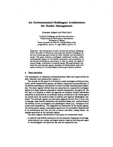
their importance. With packet-oriented communications, this Selective Cell Discard (SCD) can be significantly improved. Indeed, the drawback of SDC is that the transmission of useless cells, e.g. in our case tail of corrupted MPEG video slices, can congest upstream switches. The alternate strategy is to drop all subsequent cells from a slice as soon as once cell has been dropped. This strategy is also referred as Partial Packet Discard (PPD) and has been widely studied for improving the effective throughput of TCP connections [Romanov, 1994]. In [Mehaoua, 1997a], a variant of PPD called Adaptive Partial Slice Discard (Adaptive-PSD) has been proposed to cope with this problem in video networking environment. The proposed approach consists to select the packet (e.g. video slice) to be dropped with respect to MPEG data hierarchy and congestion level (e.g. switch queue length). In this paper we propose enhancement to this mechanism to support Forward Error Correction feature and automatic switch parameters control. The new scheme, named Partial Slice Discard with FEC support (FEC-PSD), is performed at both Control Block (CB) and video slice levels. Let us define a Control Block as a two dimensional matrix of N cells column x M rows into which consecutive fixed length AAL5 SSCS (Service Specific Convergence Sublayer) Protocol Data Units are written row by row together with FEC information. Our approach is to reduce the number of corrupted MPEG video slices by assuming that a number ‘DT’ of cells per control block can be recovered by the destination AAL5-SSCS using FEC techniques. Let us define the parameter ‘DT’ as the Drop Tolerance which corresponds to the maximum number of cells per control block that may be discarded by the FEC-PSD scheme before considering the control block as definitively lost. Picture Level Slice Level Control Block Level Cell Level
Control Block + Cell Boundaries
Slice + Control Block + Cell Boundaries
Frame + Slice + Control Block + Cell Boundaries
Figure 1 - Multi-level Data Unit Boundaries Therefore, unlikely to the simple Adaptive-PSD scheme, FEC-PSD stops discard as soon as the congestion decreases and only if the number of previously dropped cells in every control Block is below the FEC drop tolerance ‘DT’. Using this approach, the proposed scheme acts at a finer data granularity (e.g. Control Block) and better preserves entire slices from elimination.
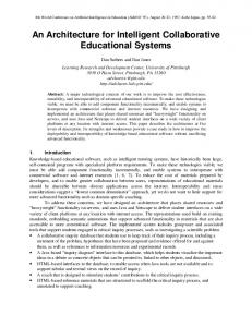
To ensure a high efficiency for FEC-PSD, slice boundaries have to be correctly managed. Therefore, three data structuring conditions have to be respected by the source before transmission and are summarized in Figure 1 and 2. (1) Every MPEG-2 Transport Stream packet [ISO, 1995] is composed with data from a single video slice. (2) A control block (CB) is constituted with data from only one video slice. (3) A cell embeds data from just one video slice. Fra m e He a d e r
MPEG-2 Picture Level (Elementary Stream)
Acces Unit Sl ice He ad e r
Slice 1
Va ri a bl e le n g th P aylo a d
Slice 2
MPEG-2 Video Slice Level
Slice 3
Sl ice PE S P a cke t He a de r (6 b yte s)
Va ria b le le n g th Pa yl oa d
PE S P acke t
MPEG-2 Packetized Elementary Stream (PES) Level
M PEG 2 T S He ad e r (4 b yte s)
MPEG-2 Transport Stream (TS) Level Ad a p ta ti o n Fie l d (u sed fo r b it stu ffin g )
T S Pa cket Fixe d le n g th Pa ylo a d (1 8 8 b yte s)
+ FEC data
Control Block (CB) Level (AAL5 SSCS)
+ FEC data CPCS T ra il e r (8 Byte s)
ATM Adaptation Layer 5 Common Part (AAL5 CPCS)
AAL5 PDU
AAL5 PDU
5 b yte s Cell
Cell
..........
EOB
EOS
Cell
Cell
..........
Cell
EOB
ATM Cell Level
Figure 2 - MPEG-2 Video Slice-based PES Encapsulation using variable length packet Let us define a low (res. high) priority slice as a slice belonging to a low (res. high) priority frame. During light congestion, we propose to drop a lower priority slice first rather than delayed it and give its buffer space to a higher priority slice. This approach avoids congestion worsening and maintains the mean cell transfer delay in acceptable value [Mehaoua, 1997b]. This proactive strategy is performed gradually by including high priority cells if necessary. As evaluated in [Mehaoua, 1997a], this preventive approach can significantly improve the network performance by minimizing the transmission of non useful video data before buffer overflow. The proposed FEC Partial Slice Discard algorithm is highlighted in the following.
2.2 FEC-PSD Scheme Parameters FEC-PSD scheme runs per-Virtual Circuit and employs four state variables and one counter variable to control each video connection. Two of them are associated with the slice level and the remaining ones with the control block level. (1) S_PRIORITY indicates the priority level of the current slice. The indicator is modified at the reception of the first cell of this slice in respect to its priority field (e.g. Cell Loss Priority bit). The switch is currently handling a high (S_priority=0), or a low (S_priority=1) priority slice.
(2) S_DISCARDING indicates whether the switch is currently discarding (S_discarding=1) this slice (e.g. the tail) or not (S_discarding=0). Only the last cell of a slice (EOS) can change this indicator from discarding to not discarding. Other cells will only change the flag from not discarding to discarding. (3) CB_DROPPED is a counter which indicates for the current control block the number of cells discarded by the switch. It is initialized to zero at the reception of a new control block. (4) CB_DISCARDING indicates whether the switch is currently discarding (CB_discarding=1) this control block or not (CB_discarding=0). Unlikely to the slice level control, the indicator changes from discarding to not discarding in two situations : the CB_DROPPED counter reaches the Drop Tolerance ‘DT’, or else a new block is received. Other events (e.g. cell arrivals) will only change the flag from not discarding to discarding.
(5) CB_EFCI_MARKING
indicates whether the switch is tagging (CB_EFCI_MARKING=1) or not tagging (CB_EFCI_marking=0) the EFCI (Explicit Forward Congestion Indication) bit of the cell for the current control block. Only the last cell of a block (EOB) can change this indicator from marking to not marking. Besides, only one event may provoke the modification of the state from not marking to marking : the arrival of a cell whereas CB_DISCARDING indicator is in ‘no discarding’ state and CB_DROPPED equals the tolerance ‘DT’.
The use of both CB_DISCARDING and CB_EFCI_MARKING indicators allow us to manage more efficiently losses occurring at subsequent switches and belonging to a control block. Indeed, when a block is partially discarded by a switch node, the following switches are not capable to take into account these cell losses to update the associated drop tolerance. The consequence is that the switches handle erroneous cell drop tolerance with adverse effect on algorithm performance. At the control block level, the Drop Tolerance can be seen as a loss credit shared by the crossed switches. In this paper we propose to entirely consume the loss credit as soon as a cell loss occurred. CB_DISCARDING is used to ensure that, for every control block, losses are concentrated in a single switch. If cells from a block tail arrive in a congested node, the use of EFCI marking allows the detection of non recoverable blocks since whole the drop
credit have been used by a previous switch. In this situation, we propose to commit to the slice level control by entirely dropping the remaining slice.
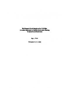
2.3 FEC-PSD Operation Modes As depicted in Figure 3, FEC-PSD uses three buffer thresholds : Low_Threshold (LT), Medium_Threshold (MT) and High_Threshold (HT). MaxQL represents the upper limit of the buffer space targeted for the UBR service. Operation Modes
O
{A1}
{A2}
LT
{A2}
MT
{A3}
HT
Qmax
Figure 3 - Switch Buffer thresholds These thresholds define three operation modes : (1) Mode {A1} : If the current buffer queue length (currentQL) is lower than Low_Threshold, for every connections having their CB_discarding indicator equal to 0, no cells are discarded. For all the other connections, the cells are accepted and may have EFCI marked if CB_EFCI is activated. (2) Mode {A2} : If the total number of cells in the buffer exceeds Low_Threshold but is still below High_Threshold, for every video connection currently emitting a low priority slice, FEC-PSD starts to discard their incoming cells in respect to the drop tolerance associated with each connection. We propose to fairly distribute the elimination among the targeted connections using round robin service. If the light congestion is subsisting, the algorithm commutes to the slice level and starts to eliminate the incoming low priority cells until the reception of an End Of Slice (EOS) cell. The last cells are always preserved from elimination since they provides indication of the next slice. The cells with higher priority are accepted in the buffer. This mode stops when currentQL falls down to Low_Threshold.
(3) Mode {A3} : This mode is activated when current QL exceeds High_Threshold. Incoming slices are eligible for discarding regardless to their priority level. This mode behaves like Mode {A2} for intelligently spreading the losses over connections with respect to their drop tolerance. It stops when the current queue length falls below HT. Using this strategy low priority B-slices are firstly dropped to quickly reduce buffer occupancy during light congestion, while high priority P- and I-slices are preserved from elimination. Indeed, statistically low priority cells (e.g. B-frames) represents about 23 % of a MPEG encoded video stream. We assume a Group of Pictures (GOP) pattern having the parameters N and M respectively equal to 12 and 2. P-cells are about 24 % and I-cells
53%. This proactive scheme will ensure a graceful and manageable Quality of Service (QoS) degradation among a set of video connections sharing the same buffer pool. By performing selective FEC strategy at destination, recoverable slices are preserved from loss while highly corrupted ones are discarded to improve the network performance (e.g. effective throughput). Using the distributed discarding approach, picture degradation are fairly and gracefully spread between the active connections. Since video connections may use different grouping modes with non-equivalent drop tolerance factors, switch nodes may virtually aggregate the drop tolerances to intelligently manage cell elimination during overload periods.
3
AN INTELLIGENT MULTI-AGENT ARCHITECTURE FOR DYNAMIC SWITCH CONTROL PARAMETERS TUNING
The lack of the proposed discarding policy is the use of static resource management and congestion control parameters. For instance, sources parameters (e.g. Drop tolerance) are negotiated at connection establishment time and can not dynamically adjust to Quality of Service (QoS) variations. Similarly, switch parameters (e.g. buffer thresholds) are initialized for the virtual path life duration and don’t take benefit to network load changes. This static approach is not optimal and can be improved by the use of an intelligent multi-agent system. The aim of this distributed agent architecture is to provide a selfregulating network control management by means of global network state awareness and agent interactions. As presented in [Schuhknet, 1995][Zhang, 1996], the primary task of these intelligent agents is to relieve the network operator from the adjustment of resource allocation and congestion control parameters (e.g. control bandwidth usage, buffer allocation, routing, resource renegotiation, ...). An agent is a self-contained software element responsible for performing part of a programmatic process [Magedanz, 1996]. It contains some level of intelligence, ranging from simple predefined rules to self-learning artificial intelligence (AI) inference machines. It acts typically on behalf of a user or a process enabling task automation. Agents operate rather autonomously and may communicate with the user, system resources and other agents as required to perform their task. Moreover, more advanced agents may co-operate with other agents to carry out tasks beyond the capability of a single agent. Among the action to be performed by the agents is the continuous monitoring of network state and the use of this knowledge to make decisions based on defined rules and policies and with respect to user goals. These challenges are achieved by the monitoring of network resources and quality parameters associated with each service class. In this article, we emphasise on the automatic adjustment of the FEC-PSD parameters (e.g. Thresholds, Drop Tolerance) in order to ensure a low cell loss ratio with a bounded end-to-end cell transfer delay.
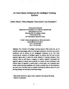
3.1 The Multi-Agents Architecture Let us define a Managed Domain (MD) as the association of two adjacent ATM switches along the virtual path connection (VPC). Each Managed Domain is under control of a high level intelligent agent (IA), referenced as the Domain Agent (DA). Intelligent Domain Agent
Domain level System level Intelligent Switch Agent 2
Intelligent Switch Agent 1
Switch 1
Switch 2 Virtual Path
Virtual Channel
Figure 4 - A Managed Domain As depicted in Figure 4, the lower architecture layer is controlled by a set of intelligent agents, named Switch Agent (SA). These autonomous agents are located at every ATM switch. The aims of SA are the monitoring of the network component behaviour (e.g. buffer queue length) and the automatic adjustment of the associated thresholds depending on directives coming from the upper Domain Agent. Since these SA have partial knowledge of the controlled system (e.g. VPC), they only act on behalf to the DA to collect and filter pertinent state information. This delegation of performance management results in a minimum control information exchange within a specific Managed Domain. The switch agents are responsible of the syntactical aspects of the management information (e.g. collection, representation and transmission), while the Domain Agent focus on the semantic aspects (intelligent processing, decision, ...). Indeed, the task of a Domain Agent is to aggregate the provisioned information from its two child and returns action directives. Since they embed a wider knowledge of the system state under control, they are able to make management decisions in the form of management action invocations and event reports at destination to the under laying switch intelligent agents.
In a different way, we can consider the presented network resource and service management multi-agent system as consisting of four sub-tasks : T.1 the collecting and the provisioning of network management relevant information, T.2 the intelligent processing of such information, T.3 the derivation of decisions regarding to both source and switch configurations, T.4 the application of these decisions In our multi-layer architecture, tasks T.1 and T.4 are hold by the Switch Agents, whereas the two others are supported by the Domain Agents. In this paper, the emphasise is only on the modification of the switch output buffer thresholds. At each system level, an agent may execute its tasks totally decoupled from its neighbour. This means that an agent operates totally asynchronously to the other agents. By using such a multi-level intelligent agent architecture, we have divided the global space into domains with manageable complexity. The induced partial knowledge faced by the system level is compensated by the reactivity and the responsiveness of the overall control. Indeed, to ensure accurate and efficient control and management decisions, reactions have to be in the order of magnitude of cell switching time. To meet this temporal requirement, inter-agent distances and control data amount should be as small as possible. Finally, the proposed architecture is sufficiently generic and systemindependent to be extended to a higher number of abstraction levels.
3.2 Intelligent Agents Cooperation and Communication Operations To support agent co-operation and communication operations, we propose the use of ATM Operation And Management (OAM) flows. Three types of OAM cells are available at the ATM layer which are differentiate by the performed function : fault management, performance management and activation/deactivation [ITU-T, 1993]. The role of fault management cells is to monitor and to test virtual connections (VPC and VCC). Performance management cells are used to monitor the performance of VPCs/VCCs and report the collected performance data such as erroneous cells and lost cells. The activation/deactivation function performs monitoring and continuity checking of connections. OAM cells can be routed at the virtual path (F4) or virtual channel level (F5). OAM cells of type F4 use the same virtual path (e.g. VPI) than user cells, but a separate virtual channel (e.g. VCI). The OAM cells of type F5 are carried in the same virtual path and channel than user cells. F4 and F5 OAM cells flow between endpoints or only on a segment of a connection depending on the value of the VCI field and the PTI field respectively. In this paper, we propose to carry control information between switch agents and the Domain Agent through F4 OAM segment flow cells. More precisely, using F4 performance management OAM cell with monitoring/reporting function type.
To collect the relevant management information, a Domain Agent inserts periodically (e.g. every fixed time interval ‘T’) a F4 OAM cell which is looped back at switch agent within a single domain (see Figure 5). The length of the domain measurement interval ‘T’ determines the accuracy and the variance of the measured quantities. Indeed, longer intervals provide lower variance but result in slower updating information (e.g. buffer thresholds). Alternatively, shorter intervals allow fast response but introduce greater variance in the response. The determination of the ‘T’ value is out of the scope of this study. Nevertheless, a ‘T’ parameter in the order of magnitude of the Round Trip Time (RTT) may be suitable and will be investigated in further works. Domain 1
Domain 2
OAM Cell
Domain 3
OAM Cell
OAM Cell
Virtual Path Virtual Connection
Figure 5 - Intelligent Agent Information Exchange Operations The structure of the OAM F4 cell is depicted in Figure 6. The unused field will contain the four parameters sent by the switch agent to the Domain Agent and the time sent by this latter to the Switch Agent.
OAM Cell Information Field
Header
0010
0010
MCSN
5 octets
4 bits
4 bits
8 bits
TUC
BIP-16
TS
Unused
16 bits 16 bits 32 bits
Block error result
Los Misinserted cell count
Reserved for future use
EDC (CRC-10)
8 bits
16 bits
6 bits
10 bits
OAM Function Type Type 33 octets
Delay
TimeMaxAdd
TimeMaxSub
Trend
Time added or deduced
Unused
Figure 6 - Operation And Maintenance F4 cell
4
SWITCH AGENT (SA)
4.1 Switch Agent Parameters The switch agent should be aware of the following local resource and control parameters (see Figure 7) : 1. the mean UBR queue length (MeanQL), 2. the available space in the shared buffer (AvSB),
3.
the output UBR port rate ( BWubr _ port ) and
4. the high UBR buffer threshold (HT). A constant method is applied to determine the values of the two other thresholds (e.g. Medium_Threshold and Low_Threshold). They are respectively set to 0.8 and 0.6 fraction of the High_Threshold. α *AvUBR γ *AvSB MeanQL
HT
AvSB Mean Queue Length AvUBR
Available Space in the shared buffer
Available Space in UBR buffer
Space used by other services CBR + VBR + ABR
Figure 7 - Switch Buffer Parameters
4.2 Switch Agent Policies and Operations The resource management policies of the switches buffers are : P.1 The agent on the switch can only use a percentage γ of the available shared space not used by the other services in addition to the maximal size allocated to the UBR+ service P.2 The Domain Agent can only decrease the size of the UBR+ switch buffer by a factor α. Periodically, each switch agent calculates and inserts the following information into the OAM F4 cell at destination to the Domain Agent :
• DELAY : The mean service delay experienced by the cells is calculated using the mean queue length (MeanQL) and the output rate of the port i ( BWubr _ port ). • TIME_MAX_ADD : The Domain Agent may ask a child to increase its High Threshold by a maximum credit service time (e.g. buffer space). He has to know the available space in the shared buffer. The switch agent has to express this quantity in term of temporal unit and is calculated as follows : γ*(number of available cell slots/ BWubr _ port ). γ represents the percentage of the shared buffer (AvSB) that the switch is allowed to use for the UBR service (policy P.1). • TIME_MAX_SUB : The Domain Agent can ask a child to decrease the size of its High Threshold by a maximum credit service time (e.g. buffer space). He should be aware of the available space in the targeted switch buffer dedicated to the UBR service (AvUBR). The agent on the switch has also to express this information in term of temporal unit and is calculated as follows: α*[(High Threshold - Mean Queue size) / BWubr _ port ]. α represents the percentage of AvUBR that the switch can liberate (in respect to the policy P.2).
• TREND : This parameter represents the tendency of the AvUBR variable. If AvUBR increases the load of the switch decreases. On the other hand, if AvUBR decreases then the load of the switch increases. This value is calculated as follows: TREND = ∂AvUBR/∂t. The first three variables are transmitted to the Domain Agent expressed in term of temporal unit (e.g. time) in order to have an homogeneous vision of the state of the two switches. This choice is explained by the fact that the switches may have different output rates with different cell service delay. Therefore the mean queue length parameter is not sufficient to allow the Domain Agent to make accurate decisions.
4.3 Switch Agent Pseudo Code Send() Repeat {DELAY_SWi = Mean Queue Length / Output_Rate /* The averaged service delay in the switch SWi*/ TimeMaxAdd_SWi = γ* (nbr_free_cell / Output_Rate) /* The maximum transit delay that the domain-agent can add to the switch SWi*/ if Mean Queue Length < Hight_Threshold then TimeMaxSub = α* [(Hight_Threshold - Mean Queue_Length)/ Output_Rate] /* The maximum transit delay that the domain-agent can subtract from the switch SWi*/ else TimeMaxSub = 0 TREND_SWi = ∂AvUBR/∂t } Receive() Repeat {At reception of t do /* t is the time credit sent by the Domain Agent */ Hight_Threshold = Hight_Threshold + t * Output_Rate }
5
DOMAIN AGENT (DA)
5.1 Domain Agent Policies The Domain Agent respects the following resource management policies: P.3
The Domain Agent distributes the credit service time between the switches in a pondered manner.
P.4
The most loaded switch will receive more credits than the other one. If necessary, High_Threshold will be decreased to maintain the same maximum domain Cell Transit Delay (maxCTD).
P.5
For every managed domain, the maximum domain transit delay experienced by a cell should be always bounded by the maxCTD negotiated during the connection setup.
Each Domain Agent must be aware of the following information switch to make a decision regarding the distribution of time credits among the two switches : the current mean transit delay of the switches (DELAY), the maximum buffer space to add to each switch (TIME_MAX_ADD), the maximum buffer space to subtract to each switch (TIME_MAX_SUB) and the switches load tendency (TREND). DA tries to dynamically allocate buffer resource (e.g. measured in cell slot times) among the two switches to ensure a minimum cell loss rate while guaranteeing the same maximum Cell Transit Delay in the domain (maxCTD). This is done by decreasing the High_Threshold of the less loaded switch (for instance SW1) and increasing the High_Threshold of the most loaded switch (for instance SW2). The deduced value can not exceed TIME_MAX_SUB for SW1 to ovoid excessive drops of incoming cells. Similarly for SW2, the added value can not exceed TIME_MAX_ADD to conform with the policies P.1 and P.2. In the case where the two switches have an increasing tendency and the current Cell Transit Delay in the domain does not exceed the maximum allowed delay (maxCTD), the Domain Agent can fairly distribute the time credits between the switches in order to reduce the cell loss rate. The credit distribution is performed in a pondered manner (in respect to policy P.3) using ’β’, while conforming with the temporal constraints of the switches (TIME_MAX_ADD and TIME_MAX_SUB).
5.2 Domain Agent Pseudo Code Repeat {if MaxCTD ≥ DELAY_SW1 + DELAY_SW2 then {case • TREND_SW1 < 0 and TREND_SW2 > 0 do {add to SW2 Min(TimeMaxAdd_SW2, TimeMaxSub_SW1) sub to SW1 Min(TimeMaxAdd_SW2, TimeMaxSub_SW1) }
/* policy P.4 */ • TREND_SW1 > 0 and TREND_SW2 < 0 do { add to SW1 Min(TimeMaxAdd_SW1, TimeMaxSub_SW2) sub to SW2 Min(TimeMaxAdd_SW1, TimeMaxSub_SW2) } /* policy P.4 */ • TREND_SW1 > 0 and TREND_SW2 > 0 do {t=(MaxCTD - DELAY_SW1 - DELAY_SW2) /* t is the available transit time */ add to SW1 Min[TimeMaxAdd_SW1, Max(β*t, t-TimeMaxAdd_SW2)] add to SW2 Min[TimeMaxAdd_SW2, Max((1-β)*t,t-timeMaxAdd_SW1)]} /* policy P.3, 0≤β≤1 */ } } }
6
CONCLUSION
Since loss and delay are a major concern for compressed video data networking, we have proposed in this paper an intelligent and automated Quality of Service (QoS) control architecture for the transmission of MPEG-encoded video applications over ATM best effort UBR+ service. A new switch scheduling and discarding policy is presented. With a better use of the hierarchical MPEG data structure as well as the support of Forward Error Correction (FEC) capabilities, the selective and adaptive Partial Slice Discarding scheme (e.g. namely FEC-PSD) overcomes the problem of picture quality degradation due to random cell drop during transient buffer congestion. The drawback of this mechanism is the use of static control parameters (e.g. buffer thresholds, drop tolerance) which significantly affect loss probability at the subsequent switching nodes. To improve its performance and simplify its management, we have designed a two-layer intelligent multi-agent system. The aim of this distributed autonomous agents architecture is to provide a self-tuning network control parameters by means of network state information exchange and agents interactions.
7
REFERENCES
ATM Forum (1996) Traffic Management Specification 4.0, at-tm-0056.000, April 1996. ISO/IEC International standard 13818-1 (1995) Generic Coding of Moving Pictures and Associated audio information : Systems, 1995. ITU-T I.610 (1993) B-ISDN Operation and Maintenance Principles Functions, Geneva, March 1993. Magedanz T., Rothermel K., Krause S. (1996) Intelligent Agents : An Emerging Technology for Next Generation Telecommunications ?, in IEEE INFOCOM’96, San Francisco, CA, March 1996.
Mehaoua A. and Boutaba R. (1997a) Performance Analysis of an Adaptive Partial Slice th Discard Scheme (A-PSD) for MPEG Video over UBR+ Service, in 13 IFIP International Conference on Computer Communications (ICCC’97), Cannes, France, November 1997. Mehaoua A., Boutaba R. and Pujolle G. (1997b) An Extended Priority Data Partition Scheme for MPEG Video Connections over ATM, in Second IEEE Symposium on Computers and Communications (ISCC’97), Alexandria, Egypt, July 1997. Romanov A. and Floyd S. (1994) Dynamics of TCP Traffic over ATM networks, in ACM SIGCOMM'94, pp. 79-88, September 1994. Schuhknet A., Dreo G. (1995) Preventing Rather Repairing : A new Approach in ATM Network Management, in INET'95 HyperMedia, Honolulu, Hawaii, June 1995. Zhang T., Covaci S., Popescu-Zeletin R. (1996) Intelligent Agents in Network and Service Management, in IEEE GLOBECOM'96, London, 1996, pp.1855-1861.
8
BIOGRAPHY
Ahmed Mehaoua received the M. Sc. degree in Computer Science from University of Paris V, France, in 1994. He is currently working toward his Ph.D. degree in Computer Science at University of Versailles, France. His main research interests are Traffic Management and Congestion Control issues in ATM networks, as well as Quality of Service Management of MPEG-encoded video applications over broadband networks. Youssef Iraqi is a doctoral candidate in Computer Science at the University of Montreal (Qc), Canada. He received the Engineering degree in Computer Science from ENSIAS high school, Mohammed V University, Morocco in 1995. His research interests include Artificial Intelligence applied to Telecommunications, Network Management and Mobile Networks. Adel Ghlamallah is a graduate student in Computer Science at University of Montreal (Qc), Canada. He received the Engineering degree in Computer Science from University of Algiers (USTHB), Algeria in 1992 and his Master degree from University of Paris V, France, in 1994. His current research involves ATM Network Management and Webbased Management.