automotive industry, they have become a main indicator of the level of ... fields, there are many smart model car contests aiming to improve college students'.
7th OAPS Working Paper Series Website: http://www.oaps.hk/
Paper No. 2010-004
An intelligent vehicle control system based on active vision Qihui XIE1
Zhe CHENG 2
1
School of Mechanical Engineering School of Naval Architecture, Ocean and Civil Engineering
2
ABSTRACT In the Freescale Cup University Smart Car Racing Contest, many cars based on traditional passive vision lose the road information because of the eye shot limitation of the camera. In order to solve this problem, this paper proposes an intelligent vehicle (IV) control system based on active vision by combining the angle of the camera with the posture of the front wheel. In this system, the IV turns the camera actively around the curve to find the guideline and make the road information be measured correctly. The paper gives an introduction to the innovative point of this proposal, i.e. the application of active vision in IV system, the significance of this design to the IV, and a series of problems and solutions during the process. The mechanical structure and control strategy of the final design are introduced as well. Experiments show that the active-vision system can evidently increase the stability and speed of the IV. Key words: Intelligent vehicle, Camera, Active vision, Image collection, Speed control
1 INTRODUCTION Intelligent and information-based technology is the developmental tendency of the automotive industry, they have become a main indicator of the level of technological sophistication [1]. Practicality is the developmental tendency of intelligent vehicle (IV). An IV with good adaptability will be the focus of research in the future. The best way to research IV based on vision navigation is experimenting on simulation models with similar mechanical architectures. So, with more and more attention being paid to research on IV and related fields, there are many smart model car contests aiming to improve college students’ ability of innovation and universities’ academic level in related field. The National University Smart Car Racing Contest hosted by Ministry of Education and co-sponsored by Freescale Semiconductor appears in this environment. With a background in rapid developing automobile electronics, the smart car racing contest covers technology innovation in subjects such as control theory, sensor technology, pattern recognition, electronic, electric, computer, mechanics etc. It aims to develop college students’ ability of innovation, study and research [2]. The rules of Freescale University Smart Car Racing Contest are as follows. Competitors “上海大学生创新活动计划”项目(IAP2007)资助
1
Qihui XIE
Zhe CHENG
School of Mechanical Engineering
must use car models provided by the organizing committee, use Freescale Semiconductor’s 8-bit or 16-bit microcontroller as the core control module, design control strategy and system, including acquiring and processing of sensors’ signal, control algorithm, motor and drive module, steering control etc, independently. Competitors should make a model car that can recognize a path independently by adding road sensors, designing motor drive circuit, coding software and assembling model. After the system is designed and debugged, the car has to drive on a track, in middle of which lays a black guiding line. The winner is the one who finishes the race in the shortest time. The contest comprises of two groups, CCD and LED. We are part of the CCD group and use cameras to navigate. The control system of smart cars includes three parts: acquiring and processing sensors’ signal, speed control and steering control. The car alters speed and steering angle according to different road conditions after the road information is acquired by the camera and processed by the microcontroller [3-4]. Through statistical analysis of the tracks from all the contests, we can find that about 60%-70% of the track is curved. So, the speed and stability on the curves will largely determine the car’s performance. In the last contest, most of the cars were based on traditional passive vision, i.e. the position and orientation of the camera cannot be controlled accurately. It is very common for them to lose the information of the road because of the limitation of the eye shot of the camera, and that will decrease the stability of the whole system. In order to improve the reliability of the image information on curves, this article puts forward some new ideas. As for a real driver, he would have to move his eyes and make the line of sight along with the curve to get more information of the road when he is on a curve. What about an IV with vision navigation system? Can it imitate this action by adjusting the camera’s direction actively? If it is possible, the car would come out to improve its performance and win the race. Through comprehensive analysis about the track, the mechanical structure of the model car, and features of the camera, we designed a control system based on active vision that can control the exact information of the road in real time.
2 GENERAL ARCHITECTURE The IV designed in this paper uses Freescale MC9S12DG128 microcontroller unit (MCU) as the core controller, and 1:10 model car as its body. A CMOS camera (OV6620) is used to collect road images. The structure of active vision includes a steering bracket, a camera bracket and a steering servo. The main difference between traditional passive vision and active vision system is that there is a steering servo to direct the camera in an active vision system. With the steering servo, IV can make its line of sight follow the track all the time by turning the camera actively. This way, the quality of road information will be improved greatly. At the same time, the stability of IV will be improved. Image information of the road is collected by the COMOS camera and then processed by MCU with an appropriate algorithm such as edge detection algorithm to get the objective guideline. After that, system will then control motor and front-wheel steering gear appropriately according
2
上海交通大学 SJTU
7th OAPS Working Paper Series
An intelligent vehicle control system based on active vision
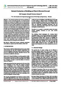
the location of the guideline. There is a sophisticated monitor around the joint of the steering to detect its real angle. IV is driven by its rear wheel through a DC motor. Closed-loop control is achieved by the rotary encoder on the drive gear. Steering gear and motor are all driven by PWM. A general architecture of the IV is shown in Figure.1.
Camer a Image Collecti ng
Steerin g gear
SSC
MC9S12DG128
Motor
Motor Drive Circuit
Figure1 Architecture of the IV
Figure 2 IV Based on active vision
Figure 3 Structure of active vision
3 DESIGN OF VISION SYSTEM The key point of achieving self-contained navigation is to recognize the location of the guideline correctly. In this system, the resolution of OV7620 camera is 640 rows * 480 lines. We use staggered scanning method to collect image information by a frame rate of 30Hz. Because of the limitation of MCU’s capability and storage space, the resolution we use is only 40 rows * 80 lines, which is much less than the resolution of the camera. The method of image collection is segmental irregular collection, which can assist in reducing the amount of information to collect and improve collection efficiency. Figure 4 shows an image collected by the method of segmental irregular collection. Because the objective guideline is a 25mm wide black line in the middle of a white track, this system uses an edge detection algorithm, which is simple but has a high capacity of anti-jamming, to work out the location of the guideline. The edge detection algorithm works in this way. Firstly, we scan the absolute value of the difference between two nearby pixels line by line [6], if the value is larger than a given threshold, then we consider it as a jumping. Then count the number of jumping when we finished scanning a line and work out the location of guideline according to the number.
上海交通大学 SJTU
3
Qihui XIE
Zhe CHENG
School of Mechanical Engineering
Figure 4 Effect of the method of segmental irregular collection
4 CONTROL SYSTEM BASED ON ACTIVE VISION 4.1 Exploration Of Control System Based On Active Vision During the research, we considered two different algorithms to adapt the mechanical structure of this IV system. They are contiguous algorithm and discrete algorithm, which are differed by the motion of servo steering camera (SSC). In discrete algorithm, the angle of SSC in respect to the body changes within some discrete values, while in contiguous algorithm, the angle of SSC in respect to the body can be any value within a certain range, it changes contiguously. The two different algorithms are introduced below, we will contrast their features and discuss which one to be the final decision.
θ str _ camera Discrete algorithm: Contiguous algorithm:
θ1 = θ 2 ...
θ str _ camera = k × α line
α line ∈ (α1 , α 2 ] α line ∈ (α 2 , α 3 ] ... k ≥0
(4-1) (4-2)
θ str _ camera
denotes the angle of SSC in respect to the body, α line denotes the angle of guideline in respect to the body. 4.1.1 Research to discrete algorithm We found that it is very easy for the IV to miss the guideline when we researched the traditional control system, i.e. when there is not any information of the track within the eye shot of the camera. When this happens, if the IV wants to turn the corner successfully, it has to slow down to a very low speed, and turn the front wheels' direction in the largest extent at the same time. This process is an open-loop control because IV can’t get any information of the load, so there is a problem with the stability of the IV system. So when we considered active vision for the first time, we liked the idea of letting the SSC turn an angle to make the guideline stay in the middle of the eye shot of the camera when the IV is going to miss the guideline. In this way, we can confirm that the guideline stays in the eye shot of the camera at all times. Therefore, the stability of IV system can be improved. Because of the angle SSC has turned, though the guideline is still in the eye shot, the IV 4
上海交通大学 SJTU
7th OAPS Working Paper Series
An intelligent vehicle control system based on active vision
body is still in a bad posture. If we continue to apply original control strategy, IV will run out of the track. So the control strategy should be improved, too. We think the most intuitionistic way is coordinate transformation, i.e. transforming the image collected by the camera after SSC turns an angle into an original image. An original image is a lattice of 40 rows * 80 lines, it extends to an image with over 80 lines after being transformed. So the technology of discrete active motion and coordinate transformation is actually a way of widening the eye shot of the camera. There would still be a lot of work to do if we choose this algorithm, because we have to consider many situations in the process of coordinate transformation. These problems are caused by the distortion of the images. Through lots of experiments we found that coordinate transformation is linear in a specific range. But even the linear coordinate transformation equations vary with the posture of the body. The equation may even be a non-linear one in some conditions, such as on a corner. 4.1.2 Research to contiguous algorithm The main principle of contiguous algorithm is to let the camera turn with the information of the road contiguously so that the image can be kept in the best position, i.e. the guideline in the center of the image, and the steering gear applies control according to the motion of SSC. 4.1.3 Contrast of two algorithms The advantage of discrete algorithm is straightforward. But it has many disadvantages. Firstly, it requires too much operation. Secondly, discrete motion is very likely to cause oscillation of SSC, especially when there are a large number of discrete points. This will decrease the stability of the IV system. Thirdly, coordinate transformation in the discrete algorithm can be challenging since it requires a lot of work. Fourthly, every time when SSC turns it needs to turn a large angle in discrete algorithm. During the long period it turns, for the speed is 160 ms/60°, the system is in under open-loop control, which will bring many problems to the control of speed and steering, such as the sudden changes of speed, wrong command to the steering gear. The advantage of contiguous algorithm is that it requires only moderate operations, which makes it easier to achieve. The disadvantage of it is that there is an additional delay caused by SSC for the IV system all the time. But thanks to the small angle SSC needs to turn during each control period, the open-loop control won’t exist in contiguous algorithm. Having considered the advantages and disadvantages of two algorithms in a comprehensive way, we chose the contiguous algorithm. 4.2 Steering control
上海交通大学 SJTU
5
Qihui XIE
Zhe CHENG
School of Mechanical Engineering
Steering can be regarded as an integrating element in the control system. The angle of steering gear is the integrand, to be evaluated as the angle varies. The variety of the voltage and workload of the steering gear has influence on the speed of integral, which directly determines the speed limit on a corner. Gain Oscillation Look-ahead distance
0
-
Steering gear Displacement
τ
e-
1 s
+
-
1 s
Posture of the body
Steering delay Figure6 Steering control system
Angle between body and track [7]
Every movement of the IV is based on the image information collected by the camera. In this system, we use control-line strategy to access the basis of control. The theory of control-line strategy is that we first transfer the image from a 40*80 array to a 20*80 virtual array by the way of irregular collection in order to decrease the distortion of the image. Then find out the furthest location of guideline within 20 lines and make it as the basis of control. In contiguous algorithm, the SSC turns according to the location of the guideline in the control-line. In this way, the guideline in the control-line can be kept in the center of the image throughout. As for the steering gear, it turns in proportion as the angle the SSC turns, but in an opposite direction, to ensure the IV drives on the tangent of the guideline. The control quantity of the steering gear is proportional to the control quantity of the SSC within certain range. In our point of view, the proportion of them should vary in different cases, it is not possible to finish the race as quick as possible with only a simplex proportion. 4.3 Speed control In a traditional vision system, speed control is based on the control-line's distance and relative position to the center. We recognize it as a straight path and apply the highest speed if the control-line is far away and near the center. If the control-line is very near and has a long distance to the center, we think the IV is on a corner. In this condition, the speed is evaluated based on a control parameter, which comes from a speed array according to the control-line. When the IV loses the guideline, it will apply the slowest speed possible. The speed control is a closed-loop strategy in this system. We contrast the feedback speed to the objective speed, if the feedback speed is smaller than the objective speed minus a given value, apply the highest speed. Instead, if the feedback speed is larger than the objective speed plus a given value, it slows down. Considering the characteristics of the active vision system, we cannot take the 6
上海交通大学 SJTU
7th OAPS Working Paper Series
An intelligent vehicle control system based on active vision
guideline’s relative position to the center as a basis for distinguishing a straight path, because the SSC can maintain the relative displacement within a range of ±2. Therefore, the SSC’s relative angle to the center should be the basis of control. It is not difficult to imagine that in this system, when the IV drives on curves, the control-line will exist much further away than a system based on passive vision, for the active vision system has improved the quality of the images. Therefore the value of the speed array on curves should be lower than it is in a system based on passive vision, or we have to consider other control strategy. The strategy we use is detecting before corners, i.e. take it as a corner and slow down when the control-line is far away and the SSC’s relative angle to the center reaches a certain value. An advantage of the active vision system is that the IV can accelerate earlier when it drives out of a corner. The reason is that the control-line will exist much further away, too. In this way, we can achieve the idealized rhythm of speed control, i.e. decelerate to enter a corner and accelerate to go out of it.
5 RESEACH TO THE STABILITY, STEADY-STATE AND DYNAMIC PERFORMANCE OF THE SYSTEM The first condition for a control system to work properly is its stability. To analysis any performance index of a system must also have the prerequisite of stability, too [5]. Compared to the traditional passive vision system, the problem we care most is that the delay during the process of image collection, the SSC rotation and front-wheel steering is too delayed for the system to make right decisions. In order to solve this problem, we paid much attention to the control program of the SSC, which leads to an effective steering control. The dynamic performance of this system lays in whether the motor and steering gear of the IV can make correct decisions according to the image information quickly. As for the SSC system, besides the stability, it should be as quick as possible, so as to reduce the delay of the whole control process. The strategy we use is measure the relative displacement of the guideline in the control-line in every control period. The control value of the motor and steering gear varies as the displacement, i.e. apply a large value if the displacement is large, and apply a small control if the displacement is small. The control values should come out from calculation and actual measurement, because excessive control will cause oscillation while too small control will cause slow response speed, which can’t meet the requirement of dynamic performance. We have a collection of data which is satisfactory for now, through lots of experiments. There is another detail which will influence the dynamic performance of the IV. The steering gear response is slower in a large displacement than in a small displacement. In the fact, the SSC needn’t to turn such a large angle. So we set clamping in the angle of ±60. If the SSC turns to the angle of 60, the system will treat it as losing line and apply a control value as it does in a passive vision system. The images recorded by a SD card shows that the guideline is always visible. So this method ensures the whole system to be closed-loop, 上海交通大学 SJTU
7
Qihui XIE
Zhe CHENG
School of Mechanical Engineering
which improves the stability. The steady-state characteristics of this system are mainly reflected in two aspects. One is the stability of the SSC, which has been introduced above, the other is the stability of tracking the guideline, which is reflected mainly on a straight line. The goal of the SSC following the guideline is to keep the guideline of the control-line in the center within a range of ±2. This steady state error should be very small to achieve the desired control. Experiments show that the method we use in this program can ensure the steady-state performance of the system, i.e. give a very small adjustment when the displacement of the guideline is small. As for the stability of tracking the guideline, the key is the control value of the steering gear. In this system, the IV determines whether the road ahead is straight, a big curve or a small curve based on the distance of the control-line and the angle of the SSC. Then give different control parameters according to different road conditions. If it is straight, give a small parameter to avoid oscillation. But a too small parameter will cause inadequate adjustment, which will result in steady-state error, i.e. the IV drives beside the guideline on straight or adjusts itself too slowly on a curve. So the control parameters should be appropriate enough to avoid both oscillation and inadequate adjustment. In addition, we have tried conditional active vision, i.e. stop the SSC when the IV is on a straight line and let it resume working on curves. Experiments show this is a good strategy, too.
5 RESEACH TO THE STABILITY, STEADY-STATE AND DYNAMIC CHARACTERISTICS OF THE SYSTEM The first condition for a control system to work properly is its stability. To analysis any performance index of a system must also have the prerequisite of stability, too. [5] Compared to the traditional passive vision system, the problem we care most is that the delay during the process of image collection, SSC rotation and front-wheel steering is too long for the system to make right decisions. In order to solve this problem, we paid many attentions to the control program of SSC, which lead to a effective steering control. The dynamic performance of this system lays in whether the motor and steering gear of IV can make correct decisions according to the image information quickly. As for the SSC system, besides the stability, it should be as quick as possible, so as to reduce the delay of the whole control process. Our strategy is to measure the relative displacement of the guideline in the control-line for every control period and then to measure the control value of the motor and varying steering gear as the displacement of the guideline changes, i.e. apply a large value if the displacement is large, and apply a small control if the displacement is small. The control values should come out from calculation and actual measurement, because excessive control will cause oscillation while too small control will cause slow response speed, which can’t meet the requirement of dynamic performance. We got a group of data which is satisfactory for now through lots of experiments.
8
上海交通大学 SJTU
7th OAPS Working Paper Series
An intelligent vehicle control system based on active vision
There is another detail which will influence the dynamic performance of the IV. The steering gear responses more slowly in a large displacement than in a small displacement. In fact, SSC needn’t to turn such a large angle. So we set clamping in the angle of ±60. If SSC turns to the angle of 60, the system will treat it as losing line and apply a control value as it does in a passive vision system. The images recorded by a SD card shows that the guideline is always visible. So this method ensures the whole system to be closed-loop, which improves the stability. The steady-state characteristics of this system are mainly reflected in two aspects. One is the stability of SSC, which has been introduced above, the other is the stability of tracking the guideline, which is reflected mainly on straight. The goal of SSC following the guideline is to keep the guideline of the control-line stay in the center within a range of ±2. This steady state error should be very small to achieve the desired control. Experiments show that the method we use in this program, i.e. give a very small adjustment when the displacement of the guideline is small, can ensure the steady-state performance of the system. As for the stability of tracking the guideline, the key is the control value of the steering gear. In this system, IV determines whether the road ahead is straight, a big curve or a small curve based on the distance of the control-line and the angle of SSC. Then give different control parameters according to different road conditions. If it is straight, give a small parameter to avoid oscillation. But a too small parameter will cause inadequate adjustment, which will result in steady-state error, i.e. the IV drives beside the guideline on straight or adjusts itself too slowly on a curve. So the control parameters should be appropriate enough to avoid both oscillation and inadequate adjustment. In addition, we have tried conditional active vision, i.e. stop SSC when IV is on straight and let it resume working on curves. Experiments show this is a good strategy, too.
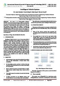
6 EXPERIMENTAL RESULTS AND ANALYSIS In order to test the performance of this control system based on active vision, we put three groups of control experiments on a track and ran them 10 times each, which is shown in Figure 7. The first group is an IV based on active vision designed in this paper. The second group is the same IV with the SSC fixed, which changes into a traditional passive vision system. The third group is a traditional IV based on passive vision. The results are listed in Table 1.
上海交通大学 SJTU
9
Qihui XIE
Zhe CHENG
School of Mechanical Engineering
Figure7 Test track (6.8m*4.8m)
Number
Table 1 Experimental result Group 1 Group 2 Active vision SSC fixed
Group 3 Traditional passive vision
1
11.207
12.350
10.612
2
11.508
12.381
10.552
3
12.304
12.672
10.312
4
11.365
12.890
Fail
5
11.324
13.401
10.551
6
11.500
Fail
10.102
7
11.342
12.364
10.532
8
11.412
Fail
10.568
9
11.301
12.381
10.601
10
11.368
12.364
10.498
The experiments show that the stability and speed of the IV based on active vision designed in this paper have been improved significantly in contrast to the IV based on passive vision in the same hardware platform. But compared to the IV based on traditional passive vision in a different hardware platform, the speed of this system is not that good, though the stability has been improved. According to the experimental data, we can find that the gap is mainly due to the mechanical structure. This indicates that there should be some improvement in mechanical structure.
7 CONCLUSIONS The paper proposes a control system of intelligent vehicle (IV) based on active vision by combining the angle of the camera with the attitude of the front wheel. After a large number of experiments, a solution is proposed, which is relatively rational. Experiments show that the quality of collected image information in active vision based control system is better than other systems, which contributes to the improvement of stability and speed. On the other hand, due to the addition of a steering, the delay and inertia of IV have been 10
上海交通大学 SJTU
7th OAPS Working Paper Series
An intelligent vehicle control system based on active vision
increased, which influence the dynamic performance greatly. So there should be some improvement in mechanical structure. The active vision is much closer to nature, because a driver in real life is actually based on active vision. Perhaps, from the perspective of current smart car contest, a system based on traditional passive vision is good enough. But as the difficulty of the contest increases year by year, active vision will reflect its irreplaceable superiority. Active vision is bound to be the preferred choice for next generation of IV system.
ACKNOWLEDGEMENTS Financial support was obtained from Shanghai Undergraduate Innovative Program in Shanghai Jiao Tong University. (Project No. IAP2007). The authors appreciate Dr. Wang Chunxiang from School of Mechanical Engineering, Shanghai Jiao Tong University, Shanghai, P.R. China for her constructive suggestions about this paper.
REFERENCE [1] LI Jun LI, Zao-heng, ZHANG Shi-yi Application of the information、digital intelligentize and systemize on vehicles[J]. Journal of Chongqing Jiaotong University, 2006(4). [2] Liu Zhilin. University smart car racing contest[J]. Microcontrollers& Embedded System, 2007(8). [3] Huang Kaisheng, Jin Huamin, Jiang Dinan. Analysis of South Korean intelligence model car technology[J]. Electronic Engineering& Product World, 2006(03S). [5] Xu Weili, Caozhuzhong, Tian Zuohua. Automatic Control Theory and Design[M]. Shanghai Jiaotong University Press. 2001-5. [6] Wei Yuhu, Shi ChenYu, Jiang Jianzhao, Chang Hua. Intelligent vehicle steering control based on vision[J]. Application of Electronic Technique. 2009(1). [7] Su Xin. Design and Implementation of Small Smart Car Auto Driving System[D]. Xi'an University of Technology- Detection Technology and Automation Equipment. 2008-3-1.
上海交通大学 SJTU
11