IEEE TRANSACTIONS ON EDUCATION, VOL. 46, NO. 1, FEBRUARY 2003
177
An Interactive Electronic Book Approach for Teaching Computer Implementation of Industrial Control Systems George Hassapis, Member, IEEE
Abstract—There is an overall consensus on the importance of laboratory work that exposes the students to broader and more practical issues of industrial control systems, such as their implementation by distributed computer systems (DCSs) and programmable logic controllers (PLCs). However, setting up appropriate laboratory facilities to serve this purpose is expensive. For this reason, an interactive learning environment has been developed around the concept of the electronic book. The architecture of the environment allows the integration of hypertext with simulators of DCS, PLC, and process operation. The simulators are specially designed to serve an application-oriented teaching approach, which involves the student in the simulation setup and the running of the application. They are able to simulate not only the execution of the software that realizes the regulatory control algorithms but also the start-up and emergency control strategies of an industrial process, the manual, automatic, and cascade modes of controller operation, and the man–machine interface of a DCS- or PLC-based control system. The applications on which the teaching of DCS and PLC-based control system implementation is based are the interactive advanced control of a distillation column and the pH control of a reactor solution. Index Terms—E-learning environments, electronic books, industrial control, teaching control systems, web-based instruction.
I. INTRODUCTION
M
ODERN control engineering courses are strongly founded on mathematical analysis and synthesis of the control algorithms and the use of relevant interactive computer tools [1]–[3]. However, these algorithms constitute only part of the implementation of a complete control system of an industrial process by typical computing devices that have been developed for industrial control applications. Two widely used classes of such devices are the programmable logic controllers [4] and the distributed computer systems (DCS) [5]. Dealing with complete industrial control systems, one must consider: • the functions of starting-up the industrial process; • operating procedures concerning process performance and emergency situations that may require bypassing the control algorithm and the human operator taking over; • safety interlocks; • alarm annunciation strategies; Manuscript received September 7, 2001; revised July 13, 2002. The author is with the Department of Electrical and Computer Engineering, Aristotle University of Thessaloniki, 54124 Thessaloniki, Greece (e-mail:
[email protected]). Digital Object Identifier 10.1109/TE.2002.808227
• the interface of the computing devices with the sensors and actuators of the process; • the presence of noise and physical constraints, such as range limits of sensors and actuators, capacity limits of interconnected equipment, etc.; • the limited computation accuracy of the computing devices; • the analog-to-digital and digital-to-analog signal conversion errors; • the delays in the program execution time. Various educators believe [6] that student exposure to these practical issues of an industrial control system is a great stimulus for developing engineering intuition and bridging the gap between theory and practice. However, setting up laboratory facilities, which will expose the students to all of these issues, is an expensive task. Therefore, the next best thing that someone could do is to set up experiments that involve the use of simulators able to handle these implementation issues of an industrial control system. The same educators believe that the use of simulators can become an effective way of teaching such issues, if their use is within the framework of a teaching model, which is different from the classical one. In the classical engineering teaching [10], [15], [26], the course material is divided into lectures that are theoretically presented in the classroom, followed by the demonstration of application examples in the laboratory. As studies have shown, more effective learning outcomes can be produced with teaching models that encourage the student to interact with the experimental setup [7]–[9] and use web-based technologies [10]–[15] to access information and knowledge related to the experiment. Taking into consideration all these findings, an extension of the interactive electronic book (i-book) approach [15] is proposed in this paper for teaching the implementation of industrial control systems with DCS and PLC systems. The i-book is a web-based technology, defined as an integration of a hypertext document with simulators. Its purpose is to replace the traditional engineering teaching by a more interactive teaching approach. Teaching by the use of virtual-control labs or simulators over the web with the purpose of increasing interaction of the student with the experimental setup can be traced in the process-control systems engineering [16]–[18] and in the DSP [19]–[21] disciplines. These attempts, however, were not able to resolve adequately the lecture–laboratory duality. They complement traditional lectures with computer-based exercises to enhance understanding. In the i-book approach,
0018-9359/03$17.00 © 2003 IEEE
178
IEEE TRANSACTIONS ON EDUCATION, VOL. 46, NO. 1, FEBRUARY 2003
TABLE I PHASES OF A CONTROL STRATEGY REALIZATION
teaching is based on the presentation of key applications broken down into individual concepts that are illustrated sequentially with a live simulation. Each simulation is wrapped by the appropriate theory in the hypertext that is linked with it. However, even in this approach, the student interaction with the simulator is limited because he or she is not involved in making the simulation. Furthermore, this approach assumes that the link with the application theory is adequate for the student to understand the concepts that the simulation is referencing, a process that might not be applicable to each individual student. In the proposed approach, the i-book is extended to include the involvement of the student in the simulation setup and provide him or her simultaneous nonsequential access to knowledge of such depth and breadth that the individual needs of the student demand. To realize this approach, interactive simulators designed especially for this purpose are required. II. THE TEACHING APPROACH According to the proposed approach, initially, the student is exposed to a web page where he or she can select one of the available experiments. These experiments are conceptually divided to present first the control problem and the strategy recommended for its solution and next the phases of the realization of this strategy by a DCS or PLC system. The considered phases are listed in Table I. To carry out the work that these phases involve, the student is required to enter the appropriate simulation environment of each experiment, i.e., the DCS environment or the PLC environment. This environment directs him or her to proceed with the realization of the control strategy by following the phases of Table I and takes in each phase the same steps that he or she should have taken toward implementing an actual DCS or PLC-based control strategy. In certain phases, some of the simulation work, which is time-consuming, has already been completed, and the student is asked only to review this work. Hyperlinks on keywords allow the student to transfer control to a tutorial-like material. The entire typical man–machine interface for completing the follow-up, automatic, and manual control actions of a professional operator are provided to the student. III. I- BOOK IMPLEMENTATION OF THE TEACHING MODEL In order to implement this teaching model, the development of web-based software is needed to allow for the integration of
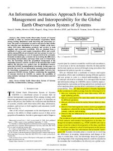
Fig. 1. Software architecture of the i-book.
hypertext with the simulator functions and services. Commercially available products for performing the functions of programming, configuring, and testing by simulation DCS-based systems, which are simultaneously able to run in a hyperlinked web environment, do not seem to exist. As far as PLCs are concerned, at least one package has been identified for programming, configuring, and simulating PLC-based systems without having the ability to run in a hyperlinked web environment. On the basis of the previous difficulties, a decision was made to proceed with the development of the appropriate DCS programming, configuration, and simulation environment, using the available package for PLCs and including in the organization of both environments the service of alternating between the theory hypertext and the simulator functions. The developed software and hypertext documents were made to run under the MS Terminal Server operating system and a SQL database server. The architecture of the developed software, consisting of a number of distinct software modules, is depicted in Fig. 1. In the following sections, the two experiments that have been developed for teaching the implementation issues of a DCS or a PLC-based industrial control system are briefly presented. By the use of these experiments, the functions offered by the environment are demonstrated. The reader may have full hands-on experience with the running of these two experiments by accessing the site mentioned in [22]. IV. DEMONSTRATION OF THE EXPERIMENTS One of the experiments is the DCS implementation of the interactive advanced control (IAC) of a distillation column. The second experiment concerns the PLC implementation of the pH control of a reactor solution. The work that each experiment requires can be completed in two sessions, each session requiring 2 h for its completion.
HASSAPIS: AN INTERACTIVE ELECTRONIC BOOK APPROACH
179
Fig. 2. Environment window in which the distillation control strategy is explained. TABLE II MODES OF DISTILLATION COLUMN OPERATION
A. The Distillation Column Control Upon the selection of this experiment, the student is presented with material of the form shown in Fig. 2. In this material, the modes of the distillation column operation, which are listed in Table II, and the parts of the control strategy that are associated with these modes are explained. For demonstration purposes and because of space limitations, a part of the strategy is presented. This part deals with the control of the endpoint temperatures of the distillate and the first and second side streams during the normal mode of column operation. A flow chart of this part of the control strategy is depicted in Fig. 3. According to this chart, the following occurs. ) • The endpoint temperature of the distillate stream ( must be controlled by a proportional-integral-derivative in the flow chart), which (PID) algorithm (function manipulates the column overhead temperature (TOH). ) • The endpoint temperature of the first side stream ( must be controlled by a PID algorithm, which manipulates the side-stream flow rate (SS1). • The interactions of the distillate stream on the first side stream must be compensated by a lead/lag algorithm in the flow chart). (function • The measurement of both endpoint temperatures must be in the flow filtered by an exponential filter (function chart).
• The value of the measurement must be extracted from the received electrical signal (function in the flow chart) by processing the output of the filter. • The endpoint temperature of the first side stream should in the flow not exceed the upper limit of 200 C (limit in the flow chart) and the lower limit of 80 C (limit chart) during the normal mode of operation. Otherwise alarm annunciation must be triggered. • Similarly, the endpoint temperature of the distillate stream in should not exceed the upper limit of 193 C (limit in the flow-chart) and the lower limit of 40 C (limit the flow chart); otherwise an alarm must be raised. According to the teaching approach of Section II, the first phase in the implementation of a control strategy is the configuration of the computing device. In the case of the DCS, the configuration involves. a) the customization of the DCS architecture to the needs of the application; b) the assignment and connection of the appropriate sensors and actuators of the measured and manipulated variables to inputs and outputs of the DCS; c) the inclusion of the control loops and the monitored variables to the appropriate display groups in the operator’s station; For the customization of the DCS architecture, the window form of Fig. 4 is displayed on the computer screen. In this window, the student is required to define the number of the local control units that make up the DCS and the number and the type of the inputs and the outputs of each local control unit. Similar window forms are shown to the student for the assignment of sensors and actuators to the inputs and outputs of the DCS. The DCS configuration ends with the operator’s station configuration, that is, the identification of the variables that will be monitored and the groups to which they will be assigned.
180
Fig. 3. Control strategy of the normal mode of distillation column operation.
IEEE TRANSACTIONS ON EDUCATION, VOL. 46, NO. 1, FEBRUARY 2003
HASSAPIS: AN INTERACTIVE ELECTRONIC BOOK APPROACH
181
sample of response curves is given in Fig. 7. The curves in this figure show how the operator managed to control manually the endpoint temperatures of the distillate and the first side stream. The deviations of the variables from their set-points shown in Fig. 7 are a result of a disturbance that occurred in the crude feed rate at the ninth sampling instant. B. The pH Control
Fig. 4. An active window for the description of the DCS architecture.
The second implementation phase involves the description of the software architecture of the control strategy. To proceed with this action, the student is exposed to the graphical environment shown in Fig. 5. In this environment, the student may draw a graph where each input filtering and conversion function is represented by a circle; each PID, compensator, and algebraic operation by a rectangle; and the conversion of each output value to a value of the electrical signal by an inverse triangle. Actually, the graph of Fig. 5 describes the architecture of the software that implements the strategy of Fig. 3. Table III lists the mnemonics of the graphical symbols that correspond to the software modules that implement the various blocks of the strategy flow chart. Now the student is required to proceed to the next phase, which is the programming of the functions that each module of the software architecture defines. Programming these functions involves embedding in the graphical symbols the names of the library routines that realize these functions and the values of their parameters. In the final testing phase, the student may perform the same functions that an ordinary operator carries out. These functions are summarized in Table IV. In order to proceed with this phase, the student is required to describe the open-loop dynamics of the considered distillation column by a matrix of transfer functions or convolution coefficients [23]. Then, he or she has to run the simulation of the distillation operation under the control of the DCS. A typical operator’s bar graph display is depicted in Fig. 6. This display presents the dynamic changes of: • the endpoint temperature of the distillate stream (PV), presented by the bar graph with the tag LCU1 S1; • the endpoint temperature of the first side stream, presented by the bar graph with the tag LCU1 S2. Both graphs include the manipulated variable (MV) and the setpoint (SP) of the respective control loop. The set-point is the value at which any controlled variable must be held. In order to revert from the manual operation of a control loop to automatic and vice versa, a button is provided at the bottom of each bar graph. The response curves of the variables over the time may be given and seen on a side window on the operator’s display. A
This experiment uses the commercially available suite of software engineering tools (ISAGRAF) [24]. This suite includes: • tools that support the editing and compilation of programs for PLCs in the languages of the IEC 61131–3 standard [25]; • facilities for program debugging and simulation of PLCbased control systems. Making the suite to run as a web application with access to the appropriate hypertext has created an environment similar to that of the DCS. Again, the student is provided with a description of the process and its control requirements. The process concerns the formation of a liquid solution with specific pH value by mixing water with hydrochloric acid solution. A schematic diagram of the process is illustrated in the upper part of Fig. 8. Initially, water is fed into tank A, at a quantity equal to half of the tank volume. A homogeneous solution that will have a pH value of 2.7 at the temperature of 70 C must be formed by adjusting the volume of the hydrochloric solution and the water poured into tank A. Hydrochloric acid and water are stored in two other tanks, B and C. The mixture is heated by an electric heater and stirred by a mixer. The process operation must be controlled by a system that performs the following functions. • Control of the flow rate of the hydrochloric acid solution stored in tank B with the purpose of decreasing the pH value. • Control of the flow rate of the water from tank C when the pH value must be increased. • Control of the tank internal temperature at the value of 70 C. • Control of the continuous stirring of the solution from the time the process starts up until it is shutdown. • Identification and alarm annunciation of abnormal operating conditions, such as tank A flooding or level of the liquid solution being below a minimum. • Monitoring the flow rates of the hydrochloric acid solution and the water, the pH value and the temperature in tank A by the use of bar graph, and analogue value indicators. Also, discrete state indicators must be provided for alarming the conditions of tank flooding, normal and low level of the liquid solution. • Bypassing the automatic operation and controlling manually the flows at the outlets of tanks A, B, and C and the temperature in tank A. In a similar way to that of the DCS, the student is instructed how to configure the architectures of the hardware and software, prepare the programming code, and test the execution of the developed software. The distinct procedural steps that are taken in each phase are briefly explained in Table V.
182
IEEE TRANSACTIONS ON EDUCATION, VOL. 46, NO. 1, FEBRUARY 2003
Fig. 5. Graphical environment for programming DCS control. TABLE III MAPPING OF THE BLOCKS OF THE STRATEGY FLOW CHART TO THE SOFTWARE MODULES OF THE PROGRAM ARCHITECTURE
Fig. 6. Operator’s display.
TABLE IV OPERATOR’S FUNCTIONS
For demonstration purposes, the display that the ISAGRAF suite provides for the implementation of the fourth step of the hardware configuration phase is shown in Fig. 8. This animated graph and this control panel are shown on the operator’s station. This graph was prepared by a general-purpose graphics package with its icons and control buttons linked with the appropriate process variables by a tool provided in the ISAGRAF suite.
Fig. 7. Response curves of the controlled variables of the distillation column.
HASSAPIS: AN INTERACTIVE ELECTRONIC BOOK APPROACH
183
Fig. 9.
Fig. 8. The animated graph and control panel of the developed industrial control system. TABLE V PROCEDURAL STEPS OF EACH IMPLEMENTATION PHASE
Assignment of variables to module channels.
veloped. This environment is an integration of hypertext with the teaching material and a set of interactive simulators of the DCS, the PLC, and the open-loop dynamic operation of the controlled process. These simulators can realize the start-up, normal, and emergency modes of operation. The student can switch from simulation to a tutorial-like presentation of the underlying theory and simulation instructions. Two experiments were set up, the first concerning the control of a distillation column by a DCS and the second concerning the pH control of a reactor solution by a PLC. REFERENCES
Fig. 9 depicts the graphical entry form used for the assignment of variables to the “sm-din1” discrete input module (3rd procedural step of the hardware configuration phase). This module receives discrete signals from the ON/OFF switches, which determine the manual or automatic mode of the operation of the actuators. Actuators are the valve that controls the flow of the hydrochloric acid (analog valve in the animated graph of Fig. 8), the dosimetric pump that controls the flow of water (dose pump in the animated graph of Fig. 8), the heater of the solution, and the solenoid valve that controls the outflow from tank A (valve ON–OFF). V. CONCLUSION This work has addressed the issue of teaching the implementation of DCS and PLC-based industrial control systems by the use of the interactive electronic book model. A web-based environment supporting the application of this model has been de-
[1] M. Johansson, M. Gäfvert, and K. J. Åström, “Interactive tools for education in automatic control,” IEEE Contr. Syst. Mag., vol. 18, pp. 33–40, June 1998. [2] B. Wittenmark, H. Haglund, and M. Johanssson, “Dynamic pictures and interactive learning,” IEEE Contr. Syst. Mag., vol. 18, pp. 26–32, June 1998. [3] S. E. Poindexter and B. S. Heck, “Using the web in the courses: What can you do? What should you do?,” IEEE Contr. Syst. Mag., vol. 19, pp. 83–92, Feb. 1999. [4] A. J. Crispin, Programmable Logic Controllers and their Engineering Applications. London, U.K.: McGraw-Hill, 1997. [5] D. Popovic and V. P. Bhatkas, Distributed Computer Control for Industrial Automation. New York: Marcel–Dekker, 1990. [6] P. Antsaklis, T. Bas¸ar, R. DeCarlo, N. H. McClamroch, M. Spong, and S. Yurkovich, “Report on the NSF/CSS workshop on new directions in control engineering education,” IEEE Contr. Syst. Mag., vol. 19, pp. 53–58, Oct. 1999. [7] E. Bilotta, M. Fiorito, D. Iovane, and P. Pantano, “An educational environment using www,” Comput. Networks ISDN Syst., vol. 27, pp. 905–909, Apr. 1995. [8] J. Self, “From constructionism to deconstructionism: Anticipating trends in educational styles,” Eur. J. Eng. Educ., vol. 22, pp. 295–307, 1997. [9] R. Kemm, D. Weaver, A. Dodds, G. Evans, D. Gartland, T. Petrovic, L. Delbridge, and P. Harris, “Designing evaluating an interactive hypothesis testing tool to aid student understanding-gastric acid secretion and its regulation,” in Proc. ASCILITE, 1997, pp. 324–330. [10] J. Allen and C. J. Terman, “An interactive learning environment for VLSI design,” Proc. IEEE, vol. 88, pp. 96–106, Jan. 2000. [11] J. McClellan, R. Schafer, J. Schoforf, and M. Yoder, “Multimedia and world wide web resources for teaching DSP,” in Proc. IEEE Int. Conf. Acoustics Speech and Signal Processing, Atlanta, GA, 1996, pp. 1101–1104.
184
[12] R. Harger, “Introducing DSP with electronic book in a computer classroom,” IEEE Trans. Educ., vol. 39, pp. 173–179, May 1996. , “Teaching in a computer classroom with a hyper linked, interactive [13] book,” IEEE Trans. Educ., vol. 39, pp. 327–335, Aug. 1996. [14] G. J. C. Copinga, M. H. G. Verhaegen, and M. J. J. M. van de Ven, “Toward a web-based study support environment for teaching automatic control,” IEEE Contr. Syst. Mag., pp. 8–19, Aug. 2000. [15] J. C. Principe, N. R. Euliano, and W. C. Lefebvre, “Innovating adaptive and neural systems instruction with interactive electronic books,” Proc. IEEE, vol. 88, pp. 81–95, Jan. 2000. [16] (2002) Virtual Control Lab 3.1. VClab, Bochum, Germany. [Online]. Available: http://vclab.esr.ruhr-uni-bochum.de/vclab [17] D. Shin, E. S. Yoon, S. J. Park, and E. S. Lee, “Web-based interactive virtual laboratory system for unit operations and process systems engineering education,” Comput. Chem. Eng., vol. 24, pp. 1381–1385, 2000. [18] D. Mahoney, B. Young, and W. Svrcek, “A completely real time approach to process control education for process systems engineering students and practitioners,” Comput. Chem. Eng., vol. 24, pp. 1481–1484, 2000. [19] V. Madisetti, J. McClellan, and T. Barnwell, “DSP design education at Georgia Tech,” in Proc. IEEE Int. Conf. Acoustics Speech Signal Processing, Detroit, MI, 1995, pp. 2869–2872. [20] J. McClellan, R. Schafer, and M. Yoder, “Experiences in teaching DSP first in the ECE curriculum,” in Proc. IEEE Int. Conf. Acoustics Speech and Signal Processing, Munich, Germany, 1997, pp. 19–22. [21] J. Schodorf, M. Yoder, J. McClellan, and R. Schaffer, “Using multimedia to teach the theory of digital multimedia signals,” IEEE Trans. Educ., vol. 39, pp. 336–341, Aug. 1996. [22] G. Hassapis. (2002) Industrial informatics. [Online]. Available: http://indinf.ee.auth.gr.
IEEE TRANSACTIONS ON EDUCATION, VOL. 46, NO. 1, FEBRUARY 2003
[23] D. E. Seborg, T. F. Edgar, and D. A. Mellichamp, Process Dynamics and Control. New York: Wiley, 1989, pp. 649–669. [24] ISAGRAF IEC 1131–3 Soft Logic. Seyssins, France: CJ Int., 1998. [25] Programmable Controllers-Part 3: Programming Languages, International Standard IEC-1131–3, 1993. [26] J. J. Zhu, “Special Issue on “A world view of control education,” IEEE Contr. Syst. Mag., vol. 16, no. 2, pp. 8–10, 1996.
George Hassapis (M’76) the degree in electrical engineering from the University of Patras, Patras, Greece, in 1973, and the M.Sc. and Ph.D. degrees from the Control Systems Centre, Institute of Science and Technology, University of Manchester, U.K., in 1975 and 1978, respectively. After completing his military service, he joined the Exxon Corporation, Thessaloniki, Greece, in 1980, where he was involved in the design and development of computer-based instrumentation and process control systems. Since October 1985, he has been with the Electrical and Computer Engineering Department, Aristotle University, Thessaloniki, where he has held the positions of the Associate Professor and the Director of the Division of Electronics and Computer Engineering, and where he is now the Director of the Laboratory of Computer Systems Architecture. His current research interests are focused on real-time computer systems, advanced computer architectures, hybrid systems, and e-learning systems. He is the author of more than 40 publications in scientific journals and conference proceedings. Dr. Hassapis is a member of the Technical Chamber of Greece and a chartered engineer of the Engineering Council of the U.K. He is also the recipient of awards from the American Biographical Institute and the International Biographical Centre.