Aug 21, 2007 - virtual exhibition presenting different flavors of digital con- tent. ... Dillenburg was integrated in the fortress in the year 1552. (see Figure 1 for an ...
EUROGRAPHICS 2007
Cultural Heritage Papers
An Interactive Exploration of the Virtual Stronghold Dillenburg S. Todt, C. Rezk-Salama, T. Horz, A. Pritzkau, and A. Kolb Computer Graphics Group, University of Siegen, Germany
Abstract This paper presents the results of an interdisciplinary project aiming at the virtual three-dimensional reconstruction of the stronghold Dillenburg, which has been completely destroyed in 1768. For an interactive virtual exploration, a high-quality 3D model was generated in close cooperation between local historians and scientists from the field of Computer Graphics based on a collection of ancient text documents, drawings and floor plans. Computer animations were generated and assembled in a DVD product for comfortable access to the virtual fortress. For the exhibition in the museum Dillenburg, a real-time application was developed for on site virtual exploration. Provided with a touch screen for interaction and a wide-screen display system, visitors can intuitively explore the virtual reconstruction and access supplemental historical background material on demand. With the multimedia installation we present a new experience which empowers visitors of the museum to explore an historical site freely at their own preferences and encourages younger audience to show more interest in cultural heritage. Categories and Subject Descriptors (according to ACM CCS): I.3.3 [Computer Graphics]: Three-Dimensional Graphics and Realism
1. Introduction Multimedia applications have become an important part in museums for content presentation. Especially interactive presentations encourage visitors to investigate cultural heritage in a totally different way. Presenting virtual models of archeological artefacts, monuments or archeological excavation sites in an interactive application empowers the visitor to explore any cultural heritage site freely and generate virtual views at his own preferences. The more freedom in virtual exploration is granted to the visitor, the more fascinating an interactive application becomes. Powerful exploration techniques, however, come at the price of complex interaction paradigms and costly equipment. Thus state-of-the-art techniques have become an essential part of modern multimedia installations in museums. State-of-the-art technology applied to historical data has the power to motivate younger generations to show interest in cultural heritage. On the other hand, computer technology tends to be a hurdle for elderly visitors who are not familiar with interaction techniques adopted from computer games and digital entertainment systems. The perfect multimedia installation accounts for both audiences. It offers a dual inc The Eurographics Association 2007. °
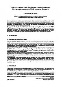
teraction paradigm, which makes the content easily available to untrained visitors and at the same time offers a more elaborate exploration technique for more experienced people. This paper presents the results of our project aiming at the virtual reconstruction of the stronghold Dillenburg. One of the unique challenges of this project was the fact that only very little remains of the stronghold still exist today. The reconstruction thus had to be performed on the basis of textual descriptions, ancient drawings and rough sketches. As an example, the most detailed historical drawing of the stronghold was created by biologist Dörrien in 1760 and is depicted in Figure 1. Although very accurate, there are many aspects in this drawing which are contradicting with other historical documents. The three-dimensional reconstruction of the site was generated manually in a 3D modeling application based on historical records, drawings and conserved floor plans in close cooperation with historians and experts of the local museum. The project includes the development of an interactive application for virtual exploration of the stronghold Dillenburg, which was integrated into an existing exhibition at the local museum. The multimedia installation consists of an intuitive
S. Todt, C. Rezk-Salama, T. Horz, A. Pritzkau, and A. Kolb / An Interactive Exploration of the Virtual Stronghold Dillenburg
Figure 1: Stronghold Dillenburg before its destruction, illustrated by Catharina Helena Dörrien in 1760.
interaction device used for real-time navigation in the threedimensional virtual reconstruction of the Dillenburg site presented on a wide-screen display system. For interactive navigation purposes a touch screen is used as interaction device to allow easy access to content for untrained users and provide more powerful properties for deeper exploration. The model can be freely explored interactively using the touch screen for navigation and is accessible directly as offline animation using short cuts from the display menu. Supplemental material, like textual information, images and narration, is available from within the interactive application. Thus the application itself becomes a virtual exhibition presenting different flavors of digital content. The remainder of this paper is structured as follows. In Section 2 we give a brief historical overview of the stronghold Dillenburg. Section 3 describes the virtual reconstruction of the stronghold. The final rendering and compositing process to generate the offline animation is explained in Section 4. Real-time rendering and human computer interaction issues are discussed in Section 5. In Section 6 we draw conclusions. 2. Historical Background First mentioned in 1255 the castle Dillenburg served as settling point for the city of Dillenburg which gained municipal law in 1344. Excavation findings however indicate that the castle Dillenburg was founded as early as 1130. The castle was destroyed in the first half of the 14th century within the Dernbach Feud for the first time. Between 1453 and 1473 it was rebuilt and continuously expanded during the following years. Within this period the castle was extended to a stronghold. The High Wall, a wall of 300m length and 25m height was completed in 1535 and the church of Dillenburg was integrated in the fortress in the year 1552 (see Figure 1 for an illustration). Steadily growing, in 1583 the stronghold Dillenburg offered 156 beds, each of them double occupied, and took in about 3000 soldiers in 1600.
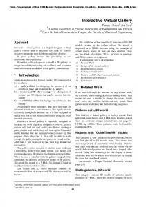
During the Thirty Years’ War (1618 – 1648) additional ten 25 pound cannons and 30 twelve pound cannons were installed. Gunpowder enough to serve for 500 shots of 1000 musketeers was placed in storage to strengthen the fortress. Dillenburg was untroubled by the war activities of the Thirty Years’ War. Within the Seven Years’ War (1756 – 1763), however, the stronghold Dillenburg was one of the main theaters of war (see Figure 2 for location and war activities). In March 1759, French forces captured the fortification for a short period of eight months before military forces counting only 100 men surprisingly reconquered it under the command of the Duke of Braunschweig. Only half a year later at the 28th of June 1760 an army of 3000 French soldiers beleaguered the stronghold again. After 13 days of massive attack by French military, Captain Düring ordered to fly the white flag on July 15th 1760. With the capitulation the stronghold Dillenburg was turned over to the French occupying power. In the following, the stronghold Dillenburg stayed seized for another four years serving as French military base in middle Europe. With the end of the Seven Years’ War Dillenburg became negligible as military base. Thus, buildings above ground were worn away and defensive fortifications were filled up and destroyed to prevent any rebuilding activities. For this reason only a few remains could be unearthed during excavations in the last decades. Starting in 1872 several buildings were constructed on the original Dillenburg site to compensate for the impressive silhouette of the stronghold. Today these buildings house a historical museum. 3. Virtual Reconstruction Due to the total destruction of the stronghold Dillenburg only a few ancient artefacts could be recovered since the first excavation in 1849. Fragmentary and contradicting information was the main challenge in the reconstruction phase. Thus, the virtual reconstruction is mainly based on historical text documents and drawings. Historical documents were recovered and interpreted by local historians for the last c The Eurographics Association 2007. °
S. Todt, C. Rezk-Salama, T. Horz, A. Pritzkau, and A. Kolb / An Interactive Exploration of the Virtual Stronghold Dillenburg The approach of Lehwalt’s army in October and November caused the Swedish army to abandon ist offensive and return to Stralsund.
Danzig
EAST RUSSIA
Lübeck Hamburg Stettin
On 30 August a Russian army of 80,000 men defeated the Prussian holding force of 25,000 at GrossJagersdorf, but failed to exploit ist victory, releasing the prussian army to turn against Swedes
Strelitz
PRUSSIA
POLAND
Berlin Frankfurt
26 July The successful D’Estre’es was removed from command after his victory at Hastenbeck. The less capable Richelieu replaced him.
Magdeburg
Battle of Rossbach 5 November
Düsseldorf
28 Nov. 12 Sept.
Strength of Soubise’s army increased to 54,00 by joining with Hildburghausen’s Imperial troops on 21 August.
17 Sept.
27 Oct.
Frankfurt Bayreuth
FRANCE
22 Nov. 15 Aug.
12 Sept.
Dillenburg
Coblenz
Battle of Leuthen 5 December.
Leipzig
Cassel
The resulting five floor plans are the main source of information for base shape and position of buildings. Unfortunately, however, there is no explicit measure available in Pfau’s drawings. At least, the drawings seemed to be consistent among each other to a great extent. The individual sketches could be aligned reasonably by least square optimization for point matching based on manually specified point correspondences.
A fient to screen Frederick’s march to Silesian culminated in a successful raid on the bridge and depot at Leutmeritz.
Only the main attack of a two pronged Austrian advnace into Lusatia and Silesia is shown.
Würzburg Pilsen Nuremberg
Regensburg Ingolstadt
AUSTRIA
HUNGARY
Ulm
Figure 2: Seven Years’ War - Operations in Saxony and Silesia, 1757. Dillenburg is marked with a black square.
decades. Based on these documents the 3D model was generated using Autodesk MayaTM 8.0 in a tedious iterative refinement process in close cooperation with the historians and the local museum. Throughout the reconstruction process, intermediate results were continuously reviewed and adapted to the historical documents and findings to minimize uncertainty and resolve contradictions. 3.1. Floor Plans Starting in 1768, the remains of the stronghold have been worn away under the supervision of Ensign Pfau. Fortunately, Pfau drew up an individual floor plan for each level of elevation (see Figure 3), before it was irretrievably destroyed.
Figure 3: Ground level floor plan of the stronghold Dillenburg drawn up by Ensign Pfau before destruction work was started in 1768. c The Eurographics Association 2007. °
Insular findings throughout the excavations of constructional work in recent years were measured and mapped by order of the local museum Dillenburg in 2005. For these remains Gauß-Krüger coordinates could be established. Aligning the floor plans generated by Pfau with the incomplete subset acquired in 2005 results in a reliable basis for our virtual reconstruction. The final alignment was performed applying a least-square five-point matching algorithm based on corresponding points common to all of the six floor plans [Nis03]. With the alignment of the additional Gauß-Krüger coordinates, a reliable indication of measurement could be retrieved for the historical drawings of Ensign Pfau.
3.2. Modeling Buildings 3D models of the constructional work were generated in two modeling phases. In the first phase a rough polygonal estimation of the buildings was modeled to establish the shape and size of the buildings. Although the base area and the position of individual buildings could be extracted directly from the floor plans, there was no explicit information concerning the height of the buildings available. Text documents describing the relative height as well as a selection of artistic perspective drawings were the only source of information. The initial geometric model served as a basis for discussion among historians and domain experts. Preliminary virtual views of the low-polygonal 3D model were generated, opening a perspective for the historians to evaluate the correctness of the historical data, that has not been available before. In an iterative process, the shape and positions of individual buildings were determined reliably within the historical context. In order to obtain information about the architectural design that could not be fully retrieved from historical data, the 3D visualization of the model allowed the historians to the make the most plausible decisions. Based on the approximated 3D shape the buildings were modeled in detail in the next step. The main features of the buildings were obtained from several perspective drawings, including the number of stories, windows, doors and dormers. These features are used for a rough structural arrangement of the building. For each individual item a placeholder was integrated into the model. By the use of those placeholders the modeling of details can be performed very efficiently. An object database was established for individual building
S. Todt, C. Rezk-Salama, T. Horz, A. Pritzkau, and A. Kolb / An Interactive Exploration of the Virtual Stronghold Dillenburg
Figure 4: Extract of the model database showing variations of window references.
details, including a series of varying flavors of doors, windows and dormers. Each individual item can then be modeled and reviewed separately. The placeholders inserted before are associated with an object selected from the database by referencing and instancing. In case of amendment the placeholders are automatically updated with every modification to the reference (see Figure 4). The same idea was also applied on a higher level of abstraction. The main scene file was set up as a collection of reference objects, as well. These references are linked to separate files containing the 3D model for each individual piece of architecture. Modifications to the reference files are automatically adopted in the main scene file. By splitting the main scene into a number of references, each part of the scene can be modeled, reviewed and mended independently. Due to a lack of reliable historical information, interiors of the buildings were not created. 3.3. Material and Texture Synthesis
Figure 5: Rendering of a corner stone segment. Procedural textures are applied to individual stones of bigger size. For larger surfaces like the walls tiled textures are used.
project, procedural textures were the choice for very few surfaces only (see Figure 5). Since high-resolution quality textures were not available for most of the materials and only small brick work textures could be acquired from conserved architecture, tiled textures had to be generated for large areas. Tiled textures tend to show noticeable patterns of repetition if they are composed from a small set of texture tiles directly without preprocessing. Special placement algorithms such as Wang Tiles are suitable to resolve the problem of repetitive patterns. However, they are not applicable within the Maya modeling environment and are in need of special image acquisition techniques [CSHD03].
Raw data for the wall textures was acquired using digital photographs from the Altena fortress, an archeological site with an architectural style similar to the stronghold Dillenburg. The synthesis of materials and textures turned out to be a time consuming and underestimated process. Ideally, equal materials must look similar but not identical throughout the complete model to avoid repetitive patterns. Thus special care must be taken in designing and assignment of materials. For untextured surfaces materials can be easily adjusted by slightly varying the material’s reflectance properties or ambient color settings.
Large textures are efficiently generated from just a single small texture sample using Bricks ’n Tiles for texture synthesis [Beg07]. Generated textures show no visual repetition patterns if rendered with closeup render settings. For long shot renderings however repetitions will inevitably become visible due to memory restrictions. Since the dominant part of the offline rendering is planned as closeup shots large textures generated within this pre-processing step are satisfactory for the first version of our project.
Texturing must account for a convincing look of our 3D model at different resolutions and levels of detail. Generating varying textures for individual polygonal surfaces represents a significant challenge. One possible solution to this problem is the use of procedural textures, which can be varied easily by adjusting the generation parameters. As performance tests have shown, however, procedural textures result in a dramatic loss in the overall rendering performance. As time and computational resources are strictly limited in our
The terrain was generated based on an actual data set generously provided by local German surveying and mapping authorities (Hessische Verwaltung für Bodenmanagement und Geoinforamtion, HVBG). For reconstruction purposes a digital terrain model (Digitales Geländemodell DGM25) was extracted for the region of interest. This data set consists of absolute elevation values per grid point, for a grid ruling of 25 m. Each grid point is associated with distinct GaußKrüger Coordinates. For terrain generation individual height
3.4. Terrain
c The Eurographics Association 2007. °
S. Todt, C. Rezk-Salama, T. Horz, A. Pritzkau, and A. Kolb / An Interactive Exploration of the Virtual Stronghold Dillenburg
points were transformed into a regular triangle mesh applying simple triangulation and subdivision methods on the height field. The Gauß-Krüger Coordinates extracted from the measurements in 2005 (see Section 3.1) can be aligned with the terrain directly. Thus the generated 3D models of the buildings can be exactly placed within the generated terrain.
be modeled directly. Animation flow can be easily adjusted by varying animation speed, aiming direction or remodeling the shape of the spline curve. 4.2. Compositing Ambient Pass
4. Rendering For rendering the footage, all of the file references were resolved and a final Maya scene file was composed including all relevant components, shaders and textures. This scene included all buildings, each of them as individual objects, the terrain, vegetation, and lights. In the final scene each building object is reviewed again. Redundant polygons are erased and unused materials are removed to simplify the scene structure and optimize for rendering performance. Finally, a sky dome was inserted, represented by a polygonal hemisphere centered around the entire geometry and textured with a fisheye photograph of a real cloudy sky. The light sources were adapted to the dominant direction of light with respect to the sky dome. The final scene consisted of 1.78 million polygons and 66 MB of texture data. Rendering was finally performed on a small PC cluster with up to 15 nodes. An overall number of 24,000 frames were rendered using Mental Ray for Maya.
Ambient Occlusion Pass
Specular Pass
Shadow Pass
4.1. Camera Settings and Animation For the final DVD version, 13 different camera animations were rendered, each with a different camera path. The flythrough of the complete scene, an eight-minute shot, represents the main part. Twelve additional camera paths showing detailed closeups of individual buildings supplement the main animation. The camera settings should be the same for all cameras to provide a consistent visual impression throughout the animations. Thus, the camera settings must be chosen to be sufficient for all different purposes. A wide opening is set to capture the dimensions of the buildings in every frame. Wide angle settings result in slight distortion artefacts, but have proven ideal to demonstrate the dimensions and impressiveness of the stronghold to the viewer.
Depth Pass
Final Composition
Mental Ray for Maya was employed for final rendering. Here the optimal tradeoff between rendering performance and image quality had to be evaluated to optimize the rendering settings. Depending on the individual rendering pass, test renderings have shown that a maximum of ten reflections, ten refractions and a maximal trace depth of 20 are best suited for our production process.
Figure 6: Compositing of five render passes to generate the final image.
Cameras were animated using spline animation, which is superior to key-frame animation for several reasons. With spline animation a visual counterpart of the camera path can
The scene was rendered in different passes and Adobe After Effects was used for image compositing. This strategy
c The Eurographics Association 2007. °
S. Todt, C. Rezk-Salama, T. Horz, A. Pritzkau, and A. Kolb / An Interactive Exploration of the Virtual Stronghold Dillenburg
is advantageous for extensive digital productions. Visual attributes can be separated into different layers. The brightness and visual appearance of the scene can be adjusted in a postprocessing step without the need to recreate any frame of footage. For optimal flexibility in the compositing step, five distinct layers were created (see Figure 6): 1. The ambient pass shows the base color of individual objects including decal textures, without any lighting, reflection or shadowing calculations. The renderer simply calculates the first hit of a viewing ray with the geometry and determines the base color of the surface at the intersection point. 2. Ambient occlusion [Lan02, ZIK98] is a simple but convincing approximation to global illumination frequently used in digital productions. The ambient occlusion pass is calculated by casting rays from a surface point in every direction on the hemisphere. The brightness value is calculated as the percentage of rays which do not intersect other parts of the geometry. 3. A separate shadow pass calculates shadows cast by all external light sources placed in the scene. 4. Specular reflection and highlights resulting from direct local illumination are calculated in a separate specular pass. 5. Finally, a depth layer is calculated providing per pixel depth information for the rendered image. However, since the depth information can be obtained during the first ambient pass, there is no need for a separate depth render pass. For the final image all the individual layers are combined. The ambient occlusion layer is used as multiplier for the ambient layer, resulting in darkening effects at edges. Specular highlights are subsequently added to yield glossy reflections. The shadow layer is blended on top of the image. The blending weight allows explicit control over the darkness in shadow regions. The result is a final image containing all the lighting and shadowing effects. The depth layer is used afterwards to create depth of field effects, and atmospheric de-saturation based on camera distance.
5. Interactive Exploration The DVD containing the computer-generated footage serves as a traditional way of presenting the reconstructed stronghold to an audience. In cooperation with the museum, we took the project one step further by using current realtime computer graphics hardware to implement an interactive walk-through. This chapter outlines important aspects of the design decisions and the implementation of such a system.
5.1. Real-Time Rendering Modern interactive 3D applications combine a rich variety of technologies including scene management, convincing realtime graphics with sophisticated lighting and shading, collision detection, navigation and interaction. It is impossible to develop such a huge amount of functionality within the scope of a cultural heritage project. Fortunately, the opensource community provides us with many free 3D graphics engines. After the comparison and evaluation of different opensource projects, we decided to use a popular free 3D-engine named OGRE [Ogr07], which stands for “Object-oriented Graphics Rendering Engine”. This engine accounts for almost all of the requirements of our project out of the box. It has a wide-spread user base, a very active forum and wiki websites, which provide the necessary support whenever needed. While some of our requirements, especially a sound-manager, are not met, the object-oriented nature of the OGRE engine makes it easy to add extra functionality via plugins. 5.2. Scene Conversion After the decision for a specific 3D-engine had been made, the process of scene conversion began. With OGRE’s native Maya-exporter, converting the geometry was not a difficult task. All the polygonal meshes for the individual buildings were converted to the native OGRE format, including the decal textures. However, the amount of data generated by directly exporting the original high-polygon-count meshes without modifications was too large for real-time rendering. Therefore, the complete model had to be revised and highlydetailed parts had to be manually simplified. To be able to interactively navigate through the stronghold, a simplified collision geometry had to be created for each building. The collision geometry was imported and used in conjunction with OGRE’s collision detection plugin. After the basic scene geometry was successfully imported into OGRE, a suitable lighting strategy had to be developed. While the offline renderings were created with Mental Ray raytracing technology, new surface shaders had to be created for real-time rendering. Our aim was to come as close as possible to the image quality of the DVD footage. We decided to implement the complete illumination of the scene by using image-based lighting and pre-calculated texture maps. Our lighting technique consists of a set of environment maps pre-filtered with different specular exponents [KM00]. Gloss maps determine the reflectivity of a surface. Normal maps are used to model surface roughness and small scale structures, such as bumps and carvings. Using these techniques realistic local illumination can be performed in realtime. Global illumination effects and shadows were added without significant loss in the overall rendering performance. All c The Eurographics Association 2007. °
S. Todt, C. Rezk-Salama, T. Horz, A. Pritzkau, and A. Kolb / An Interactive Exploration of the Virtual Stronghold Dillenburg
shadowing information had to be pre-calculated. This was achieved using Maya’s baking functionality, which allows textures containing lighting information (lightmaps) to be created fast and easily. Such texture sets were created for the shadow pass and the ambient occlusion pass described in Section 4.2. The combination of these two maps results in a good and convincing visual impression. Figure 8 shows the final rendering with overlayed control panels. 5.3. User Interaction The interaction technique used for virtual exploration must allow for different user groups of the museum to easily interact with the scene and access information at their own preferences. User groups of the museum Dillenburg tremendously differ in technical knowledge and their abilities in human-computer interaction. They further differ in historical interest and enthusiasm for cultural heritage. For those reasons the interaction technique must be easy enough for less experienced visitors but substantial enough to ignite interest in cultural heritage for those mainly attracted by the technical aspects of the virtual exploration itself. 5.3.1. Interaction Device To account for the visitors’ different technical qualification the interaction device must be both flexible and easy-to-use. The device must be robust to sustain malicious damages. It must be intuitive in usage but provide powerful interaction capabilities and the device must be stylish to smoothly fit in the museum’s exposition. Mouse and keyboard commonly used with the PC offer the highest flexibility, however, are vulnerable to manipulations to a high degree. They are far from being stylish and become too complex for navigation purposes very fast, if interaction takes more than click and text-editing actions. Using a joystick, track ball or 3D mouse for navigation in space is more intuitive, but the devices are not commonly used by elderly people. These devices are further limited in flexibility and still need additional explanation to be used by untrained users. Using a touch screen for navigation turned out to be the perfect choice for interactive multimedia installations in many types of exhibitions. Most visitors are familiar with touch screens from their everyday experience with cash dispensers and vending machines. Touch screens are robust against vandalism and can be smoothly integrated into the exhibition. The system we finally installed in the Dillenburg museum consists of a 12" LCD touch screen for interaction and a commodity wide-screen display (see Figure 7). The interactive application is running on an Intel Core 2 Duo processor with 2.4 GHz and 3.5 GB main memory and an NVidia Geforce 8800 GTX graphics board with 768 MB of local video memory. c The Eurographics Association 2007. °
Figure 7: The interactive installation at the museum Dillenburg. The touch screen in front is used for scene navigation.
5.3.2. Scene Navigation User interaction is implemented pursuing a dual approach to satisfy the needs for easy but powerful navigation. The simplicity of a touch screen is one of it’s strengths in navigation usage. The user simply needs to point at the area of interest for navigation. At the touched screen coordinates, a ray is intersected with the geometry to identify the area of interest. For a given intersection point the perfect viewpoint, from which the selected area is observed, is obtained from a list of predefined viewpoints. The scene automatically adjusts corresponding to the selected viewpoint by moving along predefined paths between two adjacent viewpoints. This "point and go" navigation is best suited for untrained users to easily explore the virtual 3D model of the stronghold Dillenburg but is limited in freedom of movement. The user is limited by predefined viewpoints and movement between those points similar to QuickTime VR applications [Che95]. Freedom of movement can be granted by implementing visual control panels for lateral and longitudinal camera motion as well as yaw and pitch for viewing direction. These GUI elements are rendered on the touch screen only (see Figure 8). This kind of navigation is related to computer game applications and preferred by trained visitors. It empowers the user to explore the complete virtual reconstruction freely. 5.3.3. Supplemental Material The interactive application becomes a hypermedium offering various flavors of detailed information on the stronghold Dillenburg by providing additional supplemental material as part of the virtual tour. According to traditional arrangements in exhibitions, this application provides context sensitive information by placing virtual information tables in front of specific scopes. The
S. Todt, C. Rezk-Salama, T. Horz, A. Pritzkau, and A. Kolb / An Interactive Exploration of the Virtual Stronghold Dillenburg
led to a reliable data basis for the final reconstruction. Enthusiastic and confident about the new archeological insights, the local authorities are currently developing plans for further excavations based on the obtained awareness from the virtual reconstruction.
Figure 8: Interactive rendering of the scene as displayed on the touch screen. The GUI elements are used to control camera translation and rotation.
For the museum Dillenburg, the multimedia installation contributes a valuable and significant extension to the exhibition. The real-time application allows visitors to explore the virtual reconstruction freely at their own preferences. It gives access to supplemental material revealing additional details and historical background about the stronghold Dillenburg. User interaction was designed to account for untrained visitors who are in need of assistance for navigation as well as experienced users being enthusiastic for new technologies. We are confident that our multimedia installation will likewise attract both user types and motivate younger visitors to show increasing interest in cultural heritage. 7. Acknowledgements
virtual tables integrate seamlessly into the overall appearance of the virtual experience. Information is presented using HTML content which can be augmented by video files, narrations and text documents. With the OGRE 3D engine an HTML render plugin is available to apply HTML content to polygonal objects as material. The plugin interprets HTML contents and renders the results to a texture, which then is applied to the faces of an object. The texture is dynamically adjusted, as the HTML content changes or the user interacts with the object. User response is fed to the HTML render engine to adjust the content accordingly. Using this HTML material for the information tables the offline animations generated previously can be accessed from within the interactive exploration application. As HTML content can be generated separately or directly accessed from the internet, supplementary material is managed very efficiently. 6. Conclusions We have presented our virtual reconstruction of the stronghold Dillenburg, including traditional computeranimated footage as well as the implementation of an interactive multimedia system. Both the DVD and the interactive application will be presented to the public starting May, 23rd 2007. The reconstruction process has shown that virtual 3D models serve as a powerful tool for the interpretation and validation of historical data. Even the initial low-polygonal model offered new ways of interpreting historical data. It has been the starting point of numerous discussions among historians and domain experts about the placement and the shape of buildings. As a result, contradictions and uncertainties could be resolved early in the first modeling phase. With a virtual reconstruction, a direct comparison of different historical interpretations has become possible, and eventually
We thank the students being responsible for 3D modeling, Matthias Hoffmann, Jan Kunze, Michael Schantin, Jens Schlemper, Sascha Schlude, Jeong Il-Sin. This project would not have been possible without the close cooperation with the Museumsverein Dillenburg eV., namely Armin Rau, Thomas Schmidt, Karlheinz Striffler, Walter Dehnert. We are grateful to the OGRE community and related projects. References [Beg07] B EGAND C.: Bricks ’n tiles. www.3drekonstruktionen.de/bricksntiles, last visited April 27th, 2007, 2007. [Che95] C HEN S. E.: Quicktime vr: an image-based approach to virtual environment navigation. In SIGGRAPH ’95: Proceedings of the 22nd annual conference on Computer graphics and interactive techniques (New York, NY, USA, 1995), ACM Press, pp. 29–38. [CSHD03] C OHEN M. F., S HADE J., H ILLER S., D EUSSEN O.: Wang tiles for image and texture generation. ACM Trans. Graph. 22, 3 (2003), 287–294. [KM00] K AUTZ J., M C C OOL M.: Approximation of glossy reflection with prefiltered environment maps. In Proc. Graphics Interface (2000). [Lan02] L ANDIS H.: Production-ready global illumination. In ACM SIGGRAPH Course Notes 16 (2002). [Nis03] N ISTER D.: An efficient solution to the five-point relative pose problem. IEEE Conference on Computer Vision and Pattern Recognition 2 (2003), 195–202. [Ogr07] O GRE 3D: Open Source Graphics Engine. www.ogre3d.org, last visited April 27th, 2007, 2007. [ZIK98] Z HUKOV S., I ONES A., K RONIN G.: An ambient light illumination model. In Proc. Eurographics Rendering Workshop (1998). c The Eurographics Association 2007. °