Abstractâ Although there are many attempts to engineer a domain specific language for the Internet of Things, most of them forget the fact that with the evolving ...
ϮϬϭϱ�yys�/ŶƚĞƌŶĂƚŝŽŶĂů��ŽŶĨĞƌĞŶĐĞ�ŽŶ /ŶĨŽƌŵĂƚŝŽŶ͕��ŽŵŵƵŶŝĐĂƚŝŽŶ�ĂŶĚ��ƵƚŽŵĂƚŝŽŶ�dĞĐŚŶŽůŽŐŝĞƐ�;/��dͿ KĐƚŽďĞƌ�Ϯϵ�ʹ�KĐƚŽďĞƌ�ϯϭ͕�ϮϬϭϱ͕�^ĂƌĂũĞǀŽ͕��ŽƐŶŝĂ�ĂŶĚ�,ĞƌnjĞŐŽǀŝŶĂ
An Internet of Things Visual Domain Specific Modeling Language based on UML 1
Teo Eterovic, 2Enio Kaljic, 2Dzenana Donko, 2Adnan Salihbegovic, 2Samir Ribic 1 ARTORG Center for Biomedical Engineering Research, University of Bern, Switzerland 2 Faculty of Electrical Engineering Sarajevo, University of Sarajevo, Bosnia and Herzegowina {teterovic, ekaljic, ddonko, asalihbegovic, sribic} @ etf.unsa.ba Abstract— Although there are many attempts to engineer a domain specific language for the Internet of Things, most of them forget the fact that with the evolving of the Internet of Things, the end user will probably be a common person without an engineering or software development background. The designers of the UML had the same problem: how to make a language powerful enough for the professionals, but at the same time simple enough to be understood by a non-technical end user that gives the requirements. Inspired by this idea a Visual Domain Specific Modeling Language was developed for the IoT and proved that it is powerful enough for the professional and at the same time simple enough to be used by non-technical users. Keywords—Internet of Things, Domain Specific Modeling Language, UML, Usability, Human computer interaction
I.� INTRODUCTION One of the open problems of the Internet of Things is how to simplify the complex system to the point that the end user can easily configure and use it [1][2][3]. The real trick is how to make the configuration language powerful to be used by a professional and at the same time to hide all the complexities and technical details from the amateur, non-developer end user who will also use it to configure his personal IoThings. The designers of UML had the same problem - how to make a language that is powerful and modular enough for the engineers when it needs to be, and at the same time simple and descriptive to be understood by the end user that specified the requirements. The good thing about UML is that a lot of advanced notations can be left out so that the end user can easily read and “write” it, on the other hand the professional is able to use the advanced notations to engineer a more complex and detailed system. II.� RELATED WORK A lot of work has been done recently in order to design THE Domain Specific Language for IoT but there is still no language that is even close enough to be the de facto or de jure language for IoT. The languages can be separated into two parts: the domain specific - textual languages and visual domain specific modeling languages. Many attempts have been made to visually model and describe a IoT System. In [10] Prehofer et al. use an informal mashup notation inspired by UML to describe the data / communication flows between IoT devices. The language uses State diagrams to model the component discrete behavior,
ϵϳϴͲϭͲϰϲϳϯͲϴϭϰϲͲϴͬϭϱͬΨϯϭ͘ϬϬ�ΞϮϬϭϱ�/���
Activity diagrams for communication flows as well as component diagrams for describing the interfaces between the devices and how they interact. Although not a language variation, a more formal UML approach has been described in [11] where they use standard UML to describe the dependencies between individual elements. For example, a class diagram is used to model the IoT resource Metamodel integration and Business Process Model and Notation - BPMN to model the processes. A similar approach has been suggested in [12] where Uckelmann et al. suggest that standard UML/BPMN could be used for modeling some segments of the IoT but isn’t specifying details how to use it. On the other hand, in [14] O'Leary describes Node-RED, an informal but very powerful visual tool for flow based IoT modeling. The visual language is a custom but very user friendly flow diagram. III.� THE LANGUAGE Although there had been attempts to use standard UML or informal notations to model IoT systems, the perfect blend that suits the technical and non-technical user has not been proven. The problem with standard UML is that it’s too complicated for non-technical users when used in a IoT system context because a lot of advanced UML expressions have to be used. On the other hand, the informal modeling languages are reinventing the wheel, although, they are not practical or not powerful enough for technical users. Therefore, a blended approach has been designed with UML, IoT systems and technical/non-technical end users in mind. The biggest challenge in designing the language was how to make a tradeoff between the variety/expression of the language in the IoT context and the simplicity for the nondeveloper - end user. The language is built from several parts: A.� Thing The Thing (alt. Device) is the basic element of the IoT system. This component is elementary by its nature and can be reused and replaced. It is also considered one of the building elements of the IoT system that can be combined with other Things in order to build the IoT system. The thing component matches a UML Component. Two types of things are introduced: a real Thing and a virtual thing that can be any device that doesn't exist in the real world, for example a software in the loop system, etc. An example is shown in Fig.1.
Fig. 1.� Two types of things a real and a virtual thing
It’s important for the things to be loosely connected with the rest of the system so that a change on one thing doesn’t affect the rest of the system. For this reason, interfaces are introduced as a way to decouple the behavior from the implementation. B.� Specification The thing is represented as a Rectangle labeled with the name of the device that matches the domain of the thing.
E.� Items One thing can contain zero or more items. The items can be divided in three groups: inputs (sensors,…), outputs (switches, sending an SMS, ...) and components (log services, software components). The items are shown as nested UML classes that are annotated as inputs and outputs . Components are similar to other items except they don’t exist physically (for example real time log, SNMP, web services....) as shown in figure 4. The inner labels of the items - the properties are used to describe the configuration of the item like the URL binding, some item specific parameters and so on.
C.� Annotation There are two types of things that are composed of several items (inputs, outputs and components). Besides a normal thing that matches a real device there is also a second type of thing with the stereotype that doesn’t exist in the real world and it’s just a virtual collection of items that are distributed in the system as shown in figure 1. D.� Encapsulation and subsystems - groups Besides the stereotype, a stereotype is available that specifies a collection of things on a higher level. For example, a subsystem could be the living room that has a series of interfaces to other rooms. Besides being just a logical group the subsystem also encapsulates the things in the same room keeping the privacy/security of the system and exposing the things only through specified interfaces. Another example would be the interaction between the subsystems Home and Work that need to communicate with each other but in the same time they have to be encapsulated to protect the privacy of the system. The subsystem element is represented as a UML subsystem block as shown in Figure 2.
Fig. 2.� The subsystem IoT element blackbox
It is also possible to show the details of the system using the White Box view as show in Figure 3.
Fig. 3.� Whitebox view of a subsystem
Fig. 4.� A thing that encapsulates varoiuse items into a logical IoT node
The items need to be loosely coupled so that they can be easily changed without affecting the rest of the system. In order to achieve this, item interfaces are introduced. The items are communicating with each other over provided and required interfaces. This enables the user to have a higher degree of control over the inter-item dependencies. The provided interface is the interface that the item is implementing. The other items are able to communicate with the item over the provided interfaces of the item. The required interface is the interface that the item needs in order to be operational. To be more precise, the item needs sometimes another item in order to be functional. In order to achieve this an item could be loosely coupled. There are three ways to show an interface: Circle, Semicircle (ball and socket), stereotype notation and a text list. F.� Circle and semicircle notation The required interface is represented as a Semicircle, while the provided interface is represented as a Circle. The name of the interface is shown in a label next to the symbol. G.� Interface stereotypes The provided and required interfaces can be represented as UML classes with the stereotype . If the item is providing an interface, then a realisation line has to be drawn from the item to the interface. If the item requires an interface, then a dependency line has to be drawn from the item to the interface. This notation is useful if the operations of the interface need to be shown.
As an alternative, a circle and semicircle notation could be used. This approach shows the same information in a much more compact way as shown in Figure 5.
Fig. 5.� The required and provided interfaces of an item. ITime – semicircle is the required itnerface and expects Time data while the IReal interface is the provided interface and sends data to a required interface.
H.� Item interface list The most compact way to display the provided and required interface of an item is to use a property list inside the item. As shown in Figure 6.
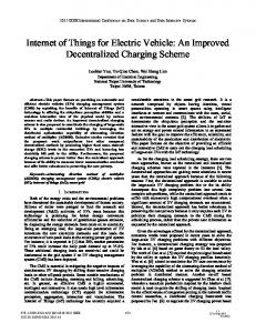
Fig. 8.� KitchenNode as a Whitebox and WorkNode as a Blackbox hiding the elements behind a port
An example of a White and Black box and how they are separated using ports is shown in Figure 9. The Home subsystem is presented as a White Box while the Work subsystem is presented as a Black box. The communication ports IMetero and ITemprature are also visible in the Figure.
Fig. 6.� Interfaces specified as a property list inside an item
It’s possible to name all the elements of the item including the additional annotations. The decision which notation to use depends on the view we want to display. I.� Items that work together In order to show that an item that has a required interface is dependent on another item in the system that is providing the interface as dependency, a line has to be drawn from the semicircle symbol to the circle symbol of the item that is providing that interface. A simple example is shown in Figure 7.
Fig. 9.� Separation of subsystems by using interfaces
K.� Rules Rules are represented as UML methods inside a UML Class block and they are closely bound to ports and items. Rules can be grouped inside Rule blocks as shown in Fig 10. Fig. 7.� Cooking log consuming(required interface) as provided IReal interface from the temperature sensor
J.� Ports and internal structure The internal structure displays the parts of the system that contains the things, items and the relations between them. This enables the representation of the relations in the specific context. The ports show how the encapsulated subsystems interact with each other by not exposing the internal interfaces of the subsystem. An example is show in Figure 8.
Fig. 10. A diagram showing Rule container and a rule with three actions
The individual operations can be modeled with UML activity diagrams or alternatives as shown in [11],[12] and [14].
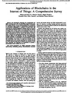
IV.� EXPERIMENT In order to test the language, a Development Environment has been developed which enables the user to configure the IoT system [15]. A Usability Test has been engineered in order to evaluate the visual domain specific language. To investigate the usability of the language for the end user, an empirical and non-empirical usability evaluation [4] has been made(heuristic) with positive field expert opinions and following industry standards like UML. An empirical evaluation has been created with the assumption that [6]: •� In a usability test adding additional subjects make it less and less likely to reveal usability issues •� About 80% of problems are found by the first 4-5 users in a usability test •� The first few users are very likely to detect most of the severe problems Three test groups have been created and although it’s generally accepted [5] that five users are enough to cover most of the usability cases, we increased the number to 11 as suggested in [9]. The test groups structure was as follows: •� Two CS PhDs with previous UML experience but no IoT experience •� Three biomedical engineers without previous UML or IoT experience •� Seven First-year students without no UML nor IoT experience The given task was a simple yet usual end user Smart Home System Configuration with three Things and two Sensors as shown in [8]. The usability measures taken into account where: •� System Usability Score •� Task Success Rate •� Time on Task • User Error Rate V.� RESULTS The experiment result is expressed as a SUS [13] (System Usability Scale) score. The average SUS score for the task given in the task we defined [8] was 81.56 what’s according to the System usability scale [7] a good to excellent result as shown in Figure 11.
Fig. 11.�System usability scale showing the result 81.6 - good to excelent [7]
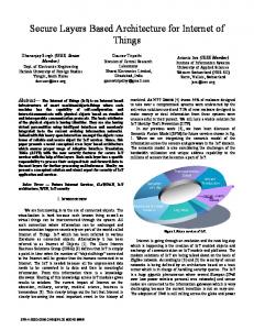
Although the experiment was rather simple, but real in the terms of a Smart Home Environment for the nontechnical user, a Task Success Rate of 100% was achieved and the User Error Rate was 0%. The results are better visible if we take a look at the distribution of the results on a histogram as shown in Figure 12.
Fig. 12.�Histogram of the results split into SUS ranges
As seen on the Figure 12, most of the users gave the language an Excellent – Best imaginable score, but the variation can also be explained with different backgrounds of the interviewed testers. An outlier is visible in the range of 3951, because of the different background of the users its better to keep the outlier within the rest of the distribution. The average Time on Task for the users was 2 minutes and 18 seconds. A slight difference between technical and non-technical users in the Time on Task has been noticed. Although we are pleased with the given results, SUS is not a diagnostic indicator, but a measure. By using SUS we where not able to find out what the real usability problems of the language are. So additional usability testing with other methods needs to be done in order to improve the usability although the usability score is satisfying. The Task Success Rate and the User Error Rate when performed with surveillance of the users could be a valuable indicator but more complex systems need to be modeled and it can’t be tested with non-technical users that where the research targets of this research. VI.� CONCLUSION An IoT Visual domain specific modeling language has been designed with UML, IoT systems and technical/non-technical end users in mind. Standardised and overall accepted usability measures have been used to prove that the language is suited for non-technical as well as technical users in terms of simplicity and real life Smart Home IoT environments. The experiment results where very promising and received a high usability scores. Although the technical users as well as nontechnical users gave a high usability score to the language, it would be reasonable to test the language for more complex IoT
Systems that need a lot of expert knowledge. Although it exceeds the scope of this paper, this experiment would test the edge cases of the proposed VDSML for professional users. Because of the compatibility with UML, advanced UML notations could be used to bring more expression to the language but for sure a subset could be created and they could be customized to better fit the IoT context.
REFERENCES [1]� Alberti AM., Singh D. Internet of Things: Perspectives, Challenges and Opportunities - International Workshop on Telecommunications (IWT), 2013 [2]� White E., "How Users (Fail to) Set Up IoT Devices", Element 14 Community, pid: wmwty3, 2014 [3]� Chatzigiannakis, I., Hasemann, H., Karnstedt, M.; Kleine, O.; Kroller, A.; Leggieri M., Pfisterer D., Romer K.; Truong,C., True selfconfiguration for the IoT, Internet of Things (IOT), 2012 3rd International Conference on the , vol., no., pp.9,15, 24-26 Oct. 2012 [4]� Farkas D. K., "Evaluation and Usability Testing", Software User Assistance (HCDE 407), Winter 2013 [5]� Virzi R. A., Refining the test phase of usability evaluation: how many subjects is enough?. Hum. Factors 34, 4 (August 1992), 457-468, 1992 [6]� Turner C. W., Lewis J. R., Nielsen J. Determining usability test sample size. In W. Karwowski (ed.), International Encyclopedia of Ergonomics and Human Factors (pp. 3084-3088). Boca Raton, FL: CRC Press, 2006 [7]� Bangor A., Kortum P., Miller J. Determining What Individual SUS Scores Mean: Adding an Adjective Rating Scale. Journal of Usability Studies, 4(3), 114-123. , 2009 [8]� Eterovic T., Simple Smart House SUS Usability Task, https://goo.gl/nVE4b5, 2015 [9]� Faulkner L. Beyond the five-user assumption: benefits of increased sample sizes in usability testing, Behav Res Methods Instrum Comput. 2003;35:379–83. doi: 10.3758/BF03195514 [10]� Christian Prehofer, Luca Chiarabin, From IoT Mashups to Model-based IoT [11]� Meyer S., Sperner K., Magerkurth C., Debortoli S., Thoma M., IoT-A Internet of Things Architecture FP7 - Project Deliverable D 2.2 – Concepts for Modelling IoT - Aware Processes, 2012 [12]� Uckelmann, D., Harrison, M., Michahelles, F.: An Architectural Approach towards the Future Internet of Things, in D. Uckelmann, F. Michahelles, & M. Harrison (Eds.), Architecting the Internet of Things. Berlin, Germany: Springer. ISBN 978-3-642-19156-5 [13]� Brooke J., SUS: a “quick and dirty” usability scale ,in: P.W. JORDAN, B. THOMAS, B.A. WEERDMEESTER, I.L. McCLELLAND (Eds.), Usability Evaluation in IndustryTaylor & Francis, London, pp. 189–194, 1996 [14]� O'Leary N., Wiring the Internet of Things with Node-RED , Solid San Francisco, 2014 [15]� Salihbegovic A., Eterovic T., Kaljic E., Ribic S, Design of a Domain Specific Language and IDE for Internet of Things Applications, 38. MiPRO Croatia, 2015