different implementations by employing standard means (i.e., XML) in order to share .... The only issue here is in converting the standardized .... It starts with the coordinator first distributing to each of the simulators in the collection ...... [17] Extensible Markup Language (XML) 1.0 (Fifth Edition). http://www.w3.org/TR/REC-.
CHAPTER 16 An Introduction to DEVS Standardization Gabriel A. Wainer, Khaldoon Al-Zoubi, Saurabh Mittal, José L. Risco Martín, Hessam Sarjoughian, Bernard P. Zeigler.
1 Introduction Since the early 70s, the M&S community has been trying to formulate approaches to modeling as system specification formalisms. As seen in the previous chapters of this book, the proliferation of DEVS-based M&S engines has brought the need to improve and standardize DEVS tools, facilitating the work of DEVS designers independently of the programming language implementations or algorithmic code expressions used. To understand the problem, let us consider that DEVS categorically separates the Model, the Simulator, and the Experimental frame. Building on this separation of concerns, the DEVS Protocol specifies the abstract simulation engine that correctly simulates DEVS atomic and coupled models. Interpreted in a distributed simulation context, the DEVS abstract simulator gives rise to a general protocol that has specific mechanisms for declaring who takes part in the simulation (the federates). It also specifies how federates interact in an iterative cycle that controls how time advances, when federates exchange messages, and perform internal state updating. A significant feature in comparison to simulation based on the HLA standard, is that if the federates in simulation are DEVS compliant then the simulation can be proved to be correct in the sense that the DEVS closure under coupling theorem guarantees a well-defined resulting structure and behavior. DEVS modeling and simulation research groups are interested in DEVS interoperability in order to enhance model composability and reusability of DEVS models and non-DEVS models in different languages and platforms. The problem to interoperate heterogeneous DEVS models with DEVS simulators is that DEVS simulators implement the DEVS modeling formalism in a growing number of diverse programming environments. Although the DEVS formalism specifies the same abstract simulator algorithm for any simulator, different simulators implement the same abstract simulator using different programming languages and environments. In other words, the model and the simulator exist in the same programming language. Consequently, legacy models as well as models that are available in one implementation are difficult to translate from one language to another (even when both the implementations are object oriented). Other constraints such as libraries inherent to the programming language (i.e., C++ or Java) are a source of complexity that prevents the desired interoperability. This is particularly important in large scale M&S, including M&S of Systems of Systems. In order to support such interoperability, various standards have been developed. The new computing methods of recent years (in particular, Grid computing and Cloud computing) introduced new ways of sharing computing power and storage in heterogeneous environments. Using these technologies, resources are virtualized as services consumed on demand (with minimal limitation for resource location). By exposing the unused resources available in most organizations, simulation performance can be improved through replication processes. This model of computation has been extremely successful, but it is still limited for more advanced simulations (for instance, when on-line interactivity is needed, for interfacing a simulation with sensor networks, etc.). Likewise, simulation interoperability on the Grid can require complex ad hoc tailoring, which is a costly and elaborate process.
Parallel simulation middleware (e.g., GATech Time Warp [1], Warped [2], SPEEDES and WarpIV [3], etc.), had usually focused on tightly coupled systems. Instead, distributed simulation middleware must allow partitioning and running simulations remotely. For instance, DIS (Distributed Interactive Simulation [4]) allowed the development of distributed simulationbased training solutions (by sharing data and computing power remotely). Other solutions included the HLA (High Level Architecture [5]), which was designed for interoperability of distributed simulation assets, and TENA (Test and Training Enabling Architecture [6]), which was built on top of CORBA (and subject to its strengths and limitations, see below) to enable real-time interoperation of assets in geographically distributed test ranges. This distributed simulation middleware focuses on data sharing, distributed processes, communication, and time management (in HLA), and has facilitated the development of large-scale distributed simulations. Nevertheless, model reuse using this kind of middleware is still difficult, ad hoc, and costly. The motivation for the discussion in this chapter stems from this need of model interoperability between the disparate simulator implementations; we intend to discuss the means to provide simulators that are transparent to model execution. We claim that a DEVSbased standard would improve sharing and interoperability of M&S assets, both locally and distributed, including specifications to facilitate a System of Systems that interact using a netcentric platform. At this level, model interoperability is one of the major concerns. As discussed earlier in this book, there are now numerous libraries and tools for expressing DEVS models across the globe, such as DEVSJAVA [7][1], DEVS/C++ [7], CD++ [8], ADEVS [9], DEVS-Suite [10], James [11], etc. (for a comprehensive list, check http://celldevs.sce.carleton.ca/devsgroup/?q=node/). Although this proliferation of libraries is witness to the numerous advantages in DEVS M&S, its multiplicity not only complicates sharing of models, it also requires modelers to learn the specific programming language in which the simulator is implemented. An important side effect of the latter is that most of the times the modelers then become locked to this language. The different designs to be discussed in this chapter show efforts to bridge the gap between the different implementations by employing standard means (i.e., XML) in order to share model information and make a step towards model interoperability and reuse. System Simulation Experiment
System
Experiments ns r tio to ca ula i f ci im pe t S l S rac e d st Simulator Simulator Mo Ab th i w
Model Model Simulator Design & Implementation
Figure 1: Concept of Standardized Independent-platform Model Representation
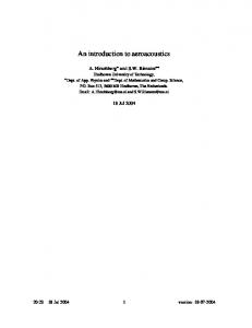
The different designs discussed in this and the following two chapters deal with two different interoperability objectives: (1) Standardizing DEVS model representation: the idea is to allow a platform-independent DEVS model representation to be executed by a DEVS-based simulator. In this case, a
DEVS model is executed on a single processor or on a parallel/distributed simulation environment. This allows model reusability without the need of performing longdistance distributed simulation. Typically, models are stored in repositories and retrieved as needed, as shown in Figure 1. In this figure, the Model boxes correspond to DEVS specifications independent of the application domain. These specifications must be independent of computer programming languages, for instance in set theory or some kind of calculus. From such formal specifications, software specifications—such as XML—can be derived. The boxes called Simulator represent the protocols that are needed to execute the specified models. By means of XML, the modeler may use a standard representation of a DEVS scenario that does not require much programming knowledge, making automatic transformations from the XML representation to a particular simulator representation. The implementations shown in this chapter are based on XML (i.e., Document Type Definition (DTD) and later on XML Schema, usually called XML Schema Definition (XSD)). (2) Standardizing Interoperability Middleware: the idea is to allow for interfacing different simulation environments, providing synchronization for the same simulation run across a distributed network regardless of their model representation, as shown in Figure 2. Heterogeneous DEVS/non-DEVS simulation models Simulation Semantics and Synchronization protocol
Model A Simulation Engine A
Model Model Model B Simulation Engine B
Distributed Simulation Middleware
Figure 2: Concept of Standardized Distributed simulation Middleware
The development of this middleware is the area of most interest to overcome current distributed simulation challenges and to meet future expectations, as indicated by a number of surveys [13][14]. Developing a standardized DEVS simulation protocol would allow enabling different DEVS implementations to simulate the same DEVS model hierarchy partitioned between various DEVS domains, while allowing all DEVS domains to execute their legacy models, performing distributed simulation experiment between different heterogeneous simulation models and engines. All middleware designs presented in this chapter offer simulation resources as consumable services. In this case, simulation entities act as peers (i.e., clients and servers at the same time) to each other to synchronize a simulation session. Each of these two objectives form two different set of standards and should be treated separately. In other words, a simulation tool does not need to conform to both sets of standards, stated above, to be able to reuse other resources from different working groups. DEVS-to-DEVS Interoperability is a basic form of interoperability that is enabled by a DEVS standard. Adoption of the DEVS standard would facilitate new development to achieve interoperability at the syntactic, semantic, and pragmatic levels. This is accomplished at the two levels stated above: model representation and middleware synchronization.
DEVS-to-Non-DEVS Interoperability is more complex. We need to establish mechanisms to implement the core simulator interface, or the Abstract Model interface to interoperate at the syntactic level with DEVS and other non-DEVS peers. In its strongest form, such simulation methodology guarantees well-defined time preservation and simulation correctness as a sound basis to aim for interoperability at the higher levels. This part relies more heavily on the middleware standard set. In this case, the middleware needs to hide as much as possible internal detailed implementation, including the DEVS formalism representation, in order to allow practical DEVS-toNon-DEVS simulation synchronization. Each of the above objectives faces different challenges. The main challenge of standardizing a DEVS model representation is in integrating the standardized representation into local simulation environments. In other words, the target simulation platform must interpret the standardized representation in a manner similar to its local model representation. For example, some DEVS tools define their models as programming language structures (e.g., Java/C++ classes). In this case, the problem extends beyond the applied programming language and also involves the complications of plugging the resulted programming structure into the overall hierarchy design of the DEVS tool. Afterwards, those models need to be compiled with DEVS tools legacy source code. In other cases, some DEVS tools define their coupled representation in tool-dependent textual format. The only issue here is in converting the standardized representation into the required textual format. Standardization independent of domain knowledge can be formulated in terms of handling different syntactical specifications and programming languages while handling alternative simulator designs, and simulator features. Syntactical interoperability can be defined in terms of the generality of the DEVS model specification and its underlying abstract simulator algorithm, both of which are independent of programming languages. Different design choices can support the same model syntax and abstract simulator semantics. In particular, the engine that performs a simulation includes features (e.g., visual component-based notation, display of simulation data trajectories, and configuration of simulation experiments) that must not have any side effect with respect to correctness of the simulator protocol [15]. On the one hand, the execution speed (performance) of the simulator may be adversely affected and on the other hand, users can benefit from important features such as simulation animation, viewing time-based trajectories, and run-time design of experiments [10]. On the other hand, standardizing a middleware protocol to execute distributed simulation between heterogeneous simulation entities faces different challenges. In this case, a programming language or other local implementation issues are not a problem, since the standardized protocol should hide and overcome these issues, as in the case of any Grid/Cloud computing system. However, the main problem is to determine how the different environments synchronize a simulation session. This includes a number of issues such as the simulation semantics (e.g., messages versus programming parameters), synchronization protocol (i.e., how information is sent and received), etc. These issues, also shown in Figure 2, are important because they affect the flexibility of improving simulation algorithms, the required amount of software changes of DEVS tools, and the ability of a DEVS tool to evolve independently with other unrelated features to the standards. In fact, current DEVS tools support distributed simulation using different underlying technology, with their own defined synchronization protocol to manage a simulation between different distributed partitions. Interoperability among different simulation engines is generally considered domain-neutral. Execution of models implemented in two or more different programming languages can be guaranteed to be DEVS-compliant for a unique abstract simulation algorithm. The specifics of a system and the conditions under which it is to be experimented with can be modeled and simulated in terms of system and experimental frame models. The simulation engine is domainneutral and the domain-specific modeling constructs are built from generic DEVS modeling
multiple single
# of Processors
constructs. It is desirable for domain-specific models to be independent of the simulation engines that can execute them.
RTDEVS/CORBA, DEVS/HLA, DEVS/SOA, …
Mixed DEVS-Suite, CD++, Adevs, …
DEVS-Suite, CD++, Adevs, …
Adevs to DEVS-Suite, DEVS-Suite to CD++, …
single
multiple
# of Programming Languages
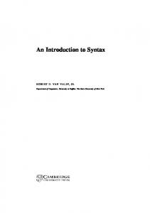
Figure 3: Centralized and distributed DEVS-based simulators
DEVS implementations have evolved independently over the years, which makes interoperating them a nontrivial task. The implementation of the DEVS formalism can range from one simulator implemented in a single programming language and executed on a single processor to multiple simulators implemented in multiple programming languages and executing on distributed processors ( Figure 3). Therefore, in order to manage complexity of simulation modeling (and more generally the entire M&S lifecycle), standardization is considered a necessity for interoperation among its different simulators and highly beneficial for non-distributed simulators.
2 Background 2.1 The DEVS Formalism For convenience of reference, let us briefly review the Discrete Event System Specification (DEVS) formalism [16] as a M&S specification that aims at studying discrete event systems. The model consists of components connected together through external port(s) where events are exchanged among models via those ports. Of course, as in any discrete-event simulation, the models being simulated change state only at discrete points in time, upon the occurrence of an event. DEVS expresses a system as a number of connected behavioral (atomic) and structural (coupled) components. The basic building block of DEVS models is the atomic DEVS model whereas coupled models connect a number of atomic or/and other coupled models. The P-DEVS formalism [15] expresses a system as a number of connected behavioral (atomic) and structural (coupled) components. A P-DEVS atomic model is formally defined as: M = where X is the set of input values; S is the set of states; Y is the set of output values; δint: S → S is the internal transition function; δext: Q x Xb → S is the external transition function, where Xb is a set of bags over elements in X, δext (s, e, φ) = (s, e); δconf: S x Xb → S is the confluent transition function; λ: S → Yb is the output function;
ta: S → R+ 0 → ∞; where Q = {(s, e) | s ∈ S, 0 ≤ e ≤ ta(s) is the total state set e is the time elapsed since last transition; At any given time, an atomic model is in some state s ∈ S. It remains in state s for the time period specified by the state time advance function ta(s), with the assumption of not receiving external events. When the lifetime of the atomic model state expires, the model outputs value λ(s) ∈ Y, and changes its state as indicated by the internal transition function δint(s). A P-DEVS model uses a bag of inputs (Xb) to exploit parallelism in the system, hence executing multiple concurrent events simultaneously. Furthermore, the model also changes its state as defined by the external transition function δext(s, e, Xb). If the atomic model receives one or more external events x ∈ X before the expiration of ta(s), it merges the functionality of multiple external transitions into a single one. A confluent transition function (δcon) is used to conclude the next state of the model, thereby resolving the collisions when receiving external events and internal transitions simultaneously. It is worth noting that the main difference between DEVS and P-DEVS formalisms is the addition of the confluent function (δconf), which is responsible for determining the next state of the model when an external input arrives at the same time of an internal transition. The definition of the confluent function is determined by the modeler so that the correct behavior can be modeled depending on the system under study. The physical system model is created by integrating different DEVS models together through their input and output ports; resulting in a coupled DEVS model. A coupled DEVS model consists of atomic and/or other coupled models connected together. A P-DEVS coupled model is formally defined as: N = Both X and Y define the sets of input and output events respectively. D is a set of indices for the components of a coupled model and, for each d ∈ D, Md is a basic P-DEVS model (atomic or coupled). The external input coupling (EIC) specifies the connections between external and component inputs, while the external output coupling (EOC) describes the connections between component and external outputs. The connections between the components themselves are defined by the internal coupling (IC). Thanks to the property known as closure under coupling, a coupled model can be reduced to a behaviorally equivalent atomic model, and thus be treated as a basic component in construction of more complicated hierarchical models.
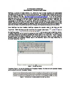
2.2 DEVS Simulation Protocol DEVS treats a model and its simulator as two distinct elements. The DEVS simulation protocol describes how a DEVS model should be simulated; whether in standalone fashion or in a coupled model. Such a protocol is implemented by a processor, which can be a simulator or a coordinator. As illustrated in Figure 4, the DEVS protocol is executed as follows: 1. It starts with the coordinator first distributing to each of the simulators in the collection each other’s addresses and then telling each of them to perform their initialization function. 2. A cycle is then entered in which the coordinator requests that each simulator provide its time of next event and determines the minimum of the returned values to obtain the global time of next event. 3. Each of the simulators applies its computeInputOutput() method to produce an output that consists of a collection of content (port/value) pairs—for DEVS simulators this is a composite message computed according to the DEVS formalism based on the current state of its model.
4. Then each simulator partitions its output into messages intended for recipient simulators and sends these messages to these recipient simulators—for DEVS simulators these recipients are determined from the output ports in the message and the coupling information that will have previously been received from the coordinator. 5. Finally, each simulator executes its ApplyDeltFunc method which computes the combined effect of the received messages and internal scheduling on its state, a side effect of which is to produce the time of next event, tN—for DEVS simulators this state change is computed according to the DEVS formalism and the tN is updated using the time advance of its model. 6. The coordinator obtains the next global time of next event and the cycle repeats.
1. nextTN
Coupled Model
Coordinator
3. getOut 4. returnOut
5. applyDelt 2. outTN Simulator tN
Simulator tN
Simulator tN
Component Model tN, tL
Component Model tN, tL
Component Model tN, tL
After each simulation step tN = t + ta(), tL = t
Component Model can be an atomic or coupled model in which case a coordinator is needed instead of a simulator.
Figure 4: Abstract parallel DEVS simulator protocol
It should be noted that although the abstract simulator is unique, its actual implementations can be quite different. This is not only because of software design, but also because of the abstract simulator itself. The abstract simulator does not impose any strict ordering for the messages sent/received when multiple components are scheduled to receive inputs at the same time. For example, when the coordinator nextTN requests are sent to two or more simulators, the order in which the outTN responses are received can be arbitrary. This is expected since the parallel DEVS formalism is defined to assume no dependency between two messages received from one or more components. Therefore, there cannot be any dependencies between two simulators that are used together in distributed fashion.
2.3 EXtensible Markup Language (XML) XML [17][18] is a specification for storing information or describing that information structure in textual documents and is increasingly adopted as a standard for the interchange of information in diverse fields of science, engineering, government, and business [12]. XML plays a major role in the DEVS model representation designs in this chapter as well, as many of them define an XML-based common model representation to be executed in any DEVS environment. It also plays a central role in the middleware standard implementation in the way simulation semantics is exchanged in form of XML messages or in the underlying technology of the distributed simulation middleware. XML is widely supported by a variety of programming environments, allowing developers to manipulate an XML-based document. XML was standardized by the World Wide Web Consortium (W3C), and it differs from other markup languages such as HTML in allowing users to define their own tags, provided they adhere to the XML standards. For example, Figure 5 shows a customized XML document, listing DEVS tools according to their name and applied programming language. In this example, we defined the “Tools” element to hold all “Tool” elements. Each “Tool” element holds two other elements: “name” and “language” elements.
CD++ C++ DEVSJAVA Java … … Figure 5: XML Document Example 1
The power of XML is its simplicity and flexibility to be extended and customized as needed. Thus, it can be used for data storage and transportation by any application. In this case, data is structured so that it can be extended or reduced (‘filtered’) as needed. For example, assume that the XML document shown in Figure 5 is transferred between two applications. In this case, for instance a new “Tool” element can be easily added to the document. On the other hand, this extensibility comes at a price. For example, the XML document shown in Figure 6 describes the same information shown in Figure 5, but differently. In this case, element “language” is renamed to element “lang”, and element “name” is converted to attribute “type”. This is easily realized by human readers with simple XML documents. Typically, though, XML documents are handled by software which considers element “name” in Figure 5 to be different from attribute “type” in Figure 6. Therefore, defining information in XML is not enough to interoperate two applications, but it is only the first step. For that reason, standardizing XML documents (i.e., structure, data, etc) is necessary to obtain practical interoperability. C++ Java … … Figure 6: XML Document Example 2
The Document Type Definition (DTD) and XML Schema, introduced in the following sections, can be used to validate XML documents (for example, the expected XML building blocks). However, the elements and attributes still need to be standardized so that communicating application can synchronize correctly.
2.3.1 Document Type Definition (DTD) DTDs define the legal building blocks (i.e., list of legal elements and attributes) of an XML document. For example, Figure 7 shows a DTD document that reads as follows: the element “Tool” contains two elements: “name” and “language”; both are of type “(#PCDATA)”, which means that these elements are only allowed to contain text (PCDATA stands for Parsed Character Data). The DTD provides more types such as EMPTY to define an empty element, or an element number of occurrence and so on.
Figure 7: DTD Example
The DTD defines rules for all the XML documents elements and attributes. However, those DTD rules must be defined in the subject XML documents, so that tools can validate XML documents against those rules. DTDs can be useful, but there are other methods, for instance, XML Schema languages (discussed next). Some of the problems of using DTDs [18] are the need for additional parsers (since it does not follow XML syntax), the lack of support for namespaces or data typing (i.e., requiring data to be integer, string, etc), and the limited capacity for defining the number of nested children elements (for a parent element).
2.3.2 XML Schema In 2001, the W3C developed a new schema to overcome the DTD shortcomings. This schema is also named XML (which is confusing since DTDs are also XML). Thus, it is often called XML Schema Definition (XSD) or, after version 1.1, XML Schema Definition Language (XSDL) [18]. XML Schema defines the legal building blocks of an XML document, as in the case of DTD. XML Schemas support data types. They are written in XML syntax; hence, are extensible and scalable. For example, Figure 8 shows two defined XML elements: “name” of type “string”, and “height” of type “integer”. Figure 8: XML Schema Example
2.4 Distributed simulation Interoperability Middleware The main objective of distributed simulation middleware is interfacing different simulation environments, allowing synchronization for the same simulation run across a distributed network, with heterogeneous simulation software components, as shown in Figure 2. For example, each simulation environment may differ from other entities in its simulation engine, algorithms, model representation, and formalism. Thus, it comes as no surprise that a number of surveys placed the middleware of distributed simulation as the area of most interest to overcome current distributed simulation challenges and to meet future expectation [19][13]. For example, a recent study carried out by Strassburger, Schulze, and Fujimoto [19] found that future efforts must include the integration of heterogeneous resources, and the joining of computer resources for complex simulations and training sessions. The study also identified some research challenges for distributed simulation middleware such as the Plug-and-Play capability. To support such capability, the middleware should couple heterogeneous models effortlessly even at runtime without prior knowledge, hence with a business mentality of “Try-before-you-buy” way of thinking via widely accepted standards in the industry. In fact, the underlying technology is the framework of the middleware; therefore, it affects the flexibility of any standards and its ability to meet current and future expectations. The Defense sector is currently one of the largest users of distributed simulation technology, mainly to provide virtual distributed training environment between remote parties, relying on the High Level Architecture (HLA) middleware to provide a general architecture for simulation interoperability and reuse [20][21][22]. The RTI software layer connects and synchronizes different HLA simulation entities (called federates), as shown Figure 9.
Federate A
Run Time Infrastructure (RTI)
Federate B
Run Time Infrastructure (RTI)
Figure 9: HLA Interaction Overview
Despite the results obtained by this standard, the current adoption of distributed simulation in the industry is still limited. Further, since its adoption in 1996, HLA has only made limited inroads in industry because of a number of issues such as its complexity and lack of interoperability in interfacing different Run-Time Infrastructure (RTI) vendors, because the RTI-to-RTI interface is not standardized. Instead, a DEVS-based standard has better prospects for successfully achieving these goals. There are several technologies that have been used to create DEVS middleware. In the following sections, we provide a brief review of each of these technologies, focusing on the way the consumers communicate with each other at the software level. This is important because standard requirements eventually need to be realized by software, hence playing a major role in defining the required changes for legacy systems software. A full analysis of distributed simulation current challenges and future trends is available in [23].
2.4.1 Common Object Request Broker Architecture (CORBA) CORBA [24] is an open standard for distributed object computing defined by the Object Management Group (OMG). CORBA object services are defined using the Interface Definition Language (IDL), which can then be compiled into programming language stubs such as C, C++, or Java (IDL syntax is similar to other programming languages). Clients in CORBA invoke methods in remote objects in remote procedure call (RPC) style fashion (using IDL stubs). The method call may return another CORBA handle (i.e., address) where the client can invoke methods of the returned object. CORBA IDL stubs and skeletons glue operations between the client and server sides. The Object Request Broker (ORB) layer provides a communication mechanism for transferring client requests to target object implementations on the server side. Building distributed simulations using CORBA is straightforward, since CORBA enables application objects to be distributed across a network. Therefore, the issue becomes identifying distributed object interfaces and defining them in IDL, hence a C++/Java local operation call becomes a remote procedure call (hidden by CORBA). Therefore, to support distributed simulation using CORBA all that is required is translating existing C++/Java simulation interfaces into a CORBA IDL definition. The use of CORBA in newly started projects has recently been declining, though. Henning [25] provides a number of reasons for this decline such as the standards complexity, the politics of accepting new standard designs, and the lack of certain needed features.
2.4.2 SOAP-based Web-services WSDL (Web-Services Definition Language) and SOAP (Simple Object Access Protocol) are the main elements that enable SOAP-based Web-services (WS) interoperability. SOAP-based Web-services provide interoperability in a similar way as CORBA: WSDL is equivalent to CORBA’s IDL role, where SOAP corresponds to ORB data marshalling/serialization function. Further, Web-service ports are addressed by Unified Resource Identifiers (URI) where CORBA
objects are addressed by references. Both ports and objects contain a collection of procedures (called services by WS) similar to Java/C++ classes. Those procedures glue software components across the network, providing an RPC-style type of software interoperability, as shown in Figure 10.
Broker (UDDI)
Service Service
Service Service
WSDL
WSDL
Port (Services) Service
RPC
Client Stubs
RPC API
RPC API
SOAP Layer HTTP Server
Figure 10: SOAP-based Web Service Client/Server Architecture [23]
The server exposes a group of services via ports; each service is actually an RPC whose semantics are described via that procedure parameters. Client programmers must construct service stubs with their software at compile time. Clients, at run time, consume a service by invoking their stub, which, in turn, is converted into an XML SOAP message (describing the RPC call). This message is usually wrapped within an HTTP message, and sent to the server port using the appropriate port URI. Once the message is received at the HTTP server, it is passed into the SOAP layer (usually called the SOAP engine). SOAP engines are usually Java programs running inside HTTP servers, called Servlets. The SOAP layer parses the SOAP message, and converts it into an RPC call applied to the appropriate procedure of the proper port. The server returns results for the clients in the same way. Thus, the SOAP message role is to provide a common representation among all parties to the invoked procedure at runtime. For example, in Figure 11 we can see that, once the procedure “boolean stopSimulation(int in0)” is invoked by a client, the SOAP engine converts it into the message shown in Figure 11 and transmits it to the server, which in turn is converted into the appropriate procedure call. The server subsequently replies in a similar way. 1 2 5 6 7 1000 8 9 10 Figure 11: SOAP Message Request Example [23]
Service providers need to publish their services as XML WSDL documents to enable clients to discover and use them. As seen in Figure 10, one way of doing so is via a broker called Universal Description, Discovery, and Integration (UDDI). UDDI is a directory for storing information about web services and is based on the World Wide Web Consortium (W3C) and Internet Engineering Task Force (IETF) standards.
Clients programming stubs (Figure 10) are generated via compiling the WSDL document. Figure 12 shows a WSDL example for the procedure “boolean stopSimulation(int in0)”. Lines 1-7 show the messages used by the Web Service to send the request and to handle the response. Lines 9-17 show the port-type definition to define the used operations by the Web Service. Lines 19-35 show the binding part, which defines the message format and ports protocol details. The element style (in Line 35) attribute uses the RPC-style. The SOAP input/output encoding style for the operation stopSimulation is defined in lines 25-33. 1 2 3 4 5 6 7 8 9 10 11 12 13 14 15 16 17 18 19 20 21 22 23 24 25 26 27 28 29 30 31 32 33 34 35
Figure 12: Excerpt of WSDL Document Example
Once the client programming stubs are generated, programmers still must write their code in the body of those stubs, and so tools are usually needed to generate templates of the source code. In practice, this process can be tedious; in particular, the tools used to generate templates usually avoid overwriting existing stubs, thus, programmers need to rewrite and validate them manually. Also, service composition scalability and lack of dynamicity may be a problem at the client side, because the stub needs to be written and compiled for every service at the server side. Dynamic invocation in Java solves this problem for Java web platforms making it the preferred environment for new developments from this perspective. RPCs are heterogeneous (because they were invented by different programmers) and distributed simulation connectivity semantics are described on the parameters of those RPCs. RPCs directly influence the interoperability integration effort, since they are actually the Application Programming Interface (API) of a simulation component. Further, RPCs often reflect the software internal implementation since they glue distributed software together.
2.4.3 REST-based Web-services The Representational State Transfer (REST) [26] style provides interoperability by imitating the World Wide Web (WWW) style and principles. REST answers the question of what makes the Web architectural style successful; hence, it is a reverse engineering of the Web architecture. REST exposes all services as resources with uniform connectors (channels) where messages are transferred between those resources through those uniform channels. REST is usually implemented using HTTP, URIs, and usually XML because these are the main pillars of the Web today. In this case, resources (services) are named and addressed by URIs, resource connectors are HTTP channels (usually called methods), and connectivity semantics are usually described in XML messages. This type of design is a recipe for a plug-and-play interoperability, as a consumer may search, locate, and consume a service at runtime. To achieve plug-and-play interoperability in a wide-range of scales, certain ingredients are needed (as in the case of the Web), as follows: • universal accepted standards (such as HTTP, URIs, and XML), • implementations are hidden in black-boxes (called resources in REST), • each resource (or service) has uniform connectors/channels (REST uses HTTP channels/methods), • each resource (or service) is addressed with universal unique identifier (i.e., URI in case of REST), and • message-oriented type of connectivity semantics (usually as XML). REST principles perfectly match the HTTP, since it is the existing Web protocol. HTTP exposes all services as URIs that can be accessed via few well-defined channels (called methods in HTTP standards): GET (to read a resource), PUT (to create/update a resource), POST (to append to a resource), and DELETE (to remove a resource). Thus, REST clients always communicate in the same standardized way, as shown in Figure 13. The client must know three things to invoke a service: (1) the service URI, (2) the HTTP channel, and (3) the message semantics and format. For example, a Web browser invokes a service from a Web site by sending a request via GET channel to that Web site URI. In response, the Web site transfers its representation in form of a message (e.g., HTML) to the client, thereby transferring the representational state to the client, as indicated by Representational State Transfer (REST) name. Synchronization Semantics (e.g. XML) Services
Client Side
Service-1 URI
HTTP Client
Service-2 URI
Dynamic Uniform way of consuming services: Consume (URI, Channel, Message (e.g. XML))
Black-box Components (resources/Services) Uniform Channels (Gates)
Figure 13: RESTful Web-service Client/Server Architecture
In contrast, SOAP-based WS exposes services as RPCs in ports where each port is addressed in a single URI. RPCs have heterogeneous interfaces, and they have a split implementation. It is worth noting that SOAP-based WS use the HTTP POST channel to transmit the description of all RPCs as SOAP messages. RESTful Web Services [27] are gaining increased attention with the advent of Web 2.0 [28] and the concept of mashup (e.g., IBM Mashup Center enterprise solutions [29]). At this point RESTful WS is supported by the leading WS tools in conjunction with the SOAP-based WS.
Mashup applications deliver new functions and services on the Web by combining different information or capabilities from more than one existing source. For example, suppose a Website is used for trip planning. In this case, based on the trip destination, this Website may display weather forecast, hotel rates, and average meal cost of the trip destination. Of course, it is impractical for a server to implement such capabilities for every possible destination in the world. Thus, this Website obtains the necessary information from different sources based on the planned trip, giving the impression of implementing these capabilities. Further, this Web site may search for this information at runtime before being able to read it. Moreover, the Website can also cache the searched results, hence enhancing performance of different users heading to similar destination. Achieving plug-and-play interoperability (in the style of the World Wide Web) for the Website in this example would not be feasible, and mashing up the various services dynamically at runtime would be very difficult. For example, the Website in the example would need to know in advance that it has to send a request to the URI of an information source via the corresponding HTTP GET channel, so it can retrieve an HTML document. If one must build a programming stub for every possible information source, the application design would be very complex, and interoperability unfeasible. Instead, the APIs of RESTful applications are expressed as URI templates [30] that can be created at runtime. Variables in URI templates (written within braces {}) are assigned at runtime by clients before a request is sent to the server, enabling clients to name their services URIs at the server side. For example, username in template can be substituted with any string to get the actual URI instance (such as or ). Further, URIs may include query variables to define the request scope by appending them to a URI after a question mark “?”. For instance, a request via GET channel to URI would instruct the Google search engine to return information only about keyword “DEVS”. Service providers usually describe their URI template either textually and/or as a Web Application Description Language (WADL) [31] document. WADL is an XML description that describes a RESTful API, hence corresponds to WSDL in SOAP-based WS. WADL describes each service as shown in Figure 14. In this example, Line #1 shows the service URI. Lines 2-11 describe the PUT channel. Lines 3-5 state that XML is the supported format by this message. Lines 6-10 define the response of requests made on the PUT channel. In this case, it only lists the possible generated faults. Lines 12-17 define the other supported channels. 1 2 3 4 5 6 7 8 BAD_REQUEST: Error while parsing XML document 9 … 10 11 12 13 … 14 15 16 … 17 18 Figure 14: Excerpt of WADL Document Example
3 Designing Interoperability of DEVS components compone The goal of a DEVS standard would be to provide a simple and mostly automated way of executing simulations that involve remote and/or heterogeneous DEVS models. This can be achieved by taking two different approaches to be discussed in the following sections: simulator-based interoperability and model-based interoperability.
3.1 Model-based based interoperability In this perspective, a distinction istinction can be made between on-line (or dynamic) and off-line (or static) interoperability, which are both centered on the models, and bring into play several methods related to Model Driven Engineering (MDE) [32]. On-line (dynamic) model-based based interoperability In on-line (dynamic) model-based based interoperability solution, models themselves are deployed as services instead of simulators. Using this model driven approach, the operations invoked through the network are no longer simulation mechanisms, but model functions, such as δint, δext, the time advance function,, etc. This extends the scope of practical DEVS interoperability. For a large class of existing model implementations it is easier to comply with this Model Interface (compared to complying with the Core Simulator Simula interface). Using a standard representation of models, different techniques can be employed to smooth the process by making the generation of the adapter mostly automated. The following describes this approach in the case of web services (see Figure 15), ), but could be extended to other integration middleware. Given a model written for a specific framework (CD++, DEVSJava, James, etc.), the first thing to do is to generate its representation in a platform-independent platform independent language (which would allow the description of the model for all the tools). This description, and more particularly the port types defined in it, can be fed into model transformation tools to generate: - A web service description, as a WSDL file. file - A wrapper that will adapt the model interface to the service interface, by forwarding the operation calls.
Figure 15: 15 Local simulation of distant and local models
Therefore, each model is assigned its own description file and its model wrapper; which are fully specialized for this particular model. In this way, model consumers are provided with complete knowledge of the nature of the messages expected by the model, increasing both type safety and understanding of the model semantics. Once this is done, the client can retrieve the description of the model, and generate a stub that will conform to its framework and behave exactly as the original model, by invoking the wrapper service. The automatic generations mentioned above can be seen as automatic transformations in the model driven engineering terminology. Regarding remote coupled models, two solutions are possible. The first is to use some kind of adapter, as in the simulatorbased approach, which will make the coupled model appear as an atomic one. The second possibility is to take into account that coupled models do not have any operational semantics. All they do is describe their ports and their couplings, in a static way. As a consequence, we can use their XML representation to generate a copy of the model in the local framework, without losing any useful information. In a nutshell, model providers: 1. Write a model in their favorite DEVS framework. 2. Automatically generate the model’s XML description, from which they generate a WSDL file and a web service encapsulating the model. 3. Deploy the web service, providing access to the underlying model. On their side, the model consumers have to: 1. Find the location of the models they need, using some kind of model directory or more classical discovery procedures such as web searches or acquaintances. 2. Give the addresses of the models’ web services to a generation tool that will download the WSDL files and generate client stubs adhering to the modeler framework. 3. Run the simulation. The framework’s simulator deals with local and remote models without even knowing it.
3.2 Simulator-based interoperability The main idea of this approach (used in DCD++ and DEVS/SOA, to be presented later), is to have a collection of simulation services distributed over the internet. These services provides several operations for simulating atomic or coupled DEVS models in a unified manner, by using the DEVS simulation protocol and the closure under coupling property of coupled models. The overall simulation is coordinated by a main service, which acts like an entry point for the user. This architecture is summarized in Figure 16.
Figure 16:: DEVS components interoperability through simulators communication
In order to communicate, the DEVS services services expose a standard interface that accepts the usual simulation protocol messages: initialize, initialize get time of next event, run transition and so on. From a user perspective, the simulation process consists of: 1. Writing a coupled DEVS model, using their favorite framework. 2. Providing a list of DEVS servers on which they wish to distribute the simulation. 3. Deploying the DEVS models to the servers (either by downloading them from their location or activating existing remote models). models) 4. Starting the simulation. It should be noted that the above is one form of many possible protocols that can provide various forms of conservative and optimistic simulation, each of which must be proved to be correct as a implementation of the DEVS closure under coupling property [10]. Implicit in the above description are the following constraints involving methods in the CoreSimulatorInterface: •
•
The sendMessages() method “must” employ the putContentOnSimulator() method as follows: for any simulator to which it wishes to send a content, it must call the recipient’s putContentOnSimulator() method with the recipient and the content as arguments. Further, in applying its computeInputOutput() method, thod, a simulator “must” be able to interpret the contents (satisfying the ContentInterface)) it has received from the other simulators.
Notice that we cannot enforce these the “must” requirements, and cannot prove that the simulation executes a desired behavior, or, unless we are given further information about its behavior. One way to do ensure these conditions is when the simulators are truly DEVS simulators in that they satisfy the interfaces and constraints given below. Failing this additional rigor, the interoperation operation involving DEVS and non-DEVS non DEVS is purely at the technical level similar to that of a federation of simulators in HLA. This contrasts with the situation in which the federation is in fact derived from a DEVS coupled model for which correct simulation of the coupled model is guaranteed according to the DEVS formalism.
4 Comparing Existing Designs and Implementations The two objectives discussed (simulator-based interoperability and model-based interoperability) face different challenges and have different purpose. Thus, they form two different sets of standards, and they can be treated separately. In other words, a simulation tool does not need to conform to both sets of standards to be able to reuse other resources from different working groups. In recent years, there have been a number of efforts to deal with these issues, and we will compare and discuss these approaches here from the two objective viewpoints.
4.1 Standardizing DEVS model representation Standardizing DEVS model representation allows a model to run on any DEVS simulation environment. This is powerful in the sense that a model can be retrieved from a repository and run locally on a different tool other than the originally intended running environment of that model. This is highly recommended to avoid performing distributed simulation between remote environments for obvious performance reasons. Different working groups have used XML as a mechanism for interchanging model information. In order to do so, we need to define an XML vocabulary, which is formally defined by an XML Schema against which every file written in the vocabulary can be automatically validated. This arrangement gives an XML vocabulary several important advantages over Platform Specific Models (PSMs): • Validation against a schema promotes stability of the standard. • The schema can restrict data types. • The schema can define key data to insure consistency in the models (including the validation of important properties in the data values, such as uniqueness or duplicity of use, when needed). • The schema can be extended to include constraint types or simulator directives. Files that are valid under the original schema continue to be valid under the extended one (though, of course, the reverse is not guaranteed). This broader relevance has benefits for DEVS systems: • When scenarios are stored in XML format, DEVS technology results are more readily integrated into broader information technology infrastructures. • XML is the data interchange language of Web services. • XML lends itself very well to compression. • XML-based eXtensible Stylesheet Language Transformations (XSLT) offer a convenient way to specify translations of XML documents. If a DEVS scenario (with perhaps corresponding results) is stored in XML, then XSLT is easily applied to the scenario to produce a Web browser document that displays the results data in reports that are suitable for people to read. • Encryption standards such as XML Encryption are emerging for XML data [12]. This encryption is important to commercial DEVS applications where the scenarios contain confidential data. Libraries for these purposes—validating files, defining keys, compressing files, and the like— are provided by numerous XML tools designed for manipulating and parsing XML data. It suffices to define our XML vocabulary in the form of a schema to utilize these tools. This contrasts to ad hoc formats that require writing, debugging, and maintaining routines equivalent to these tools.
DEVS/XML Schema
DEVS/XML Model Valid DEVS/XML Model XLST - Transformations
DEVSJAVA
DEVS/C++
CD++
xDEVS
DEVS/XML Simulators
Reverse engineering Figure 17: DEVS/XML standard definition
Figure 17 shows a DEVS/XML standard definition framework. The DEVS/XML Schema includes the grammar for both the structure and behavior of DEVS models (i.e., coupled and atomic models). When it is defined, the system designer is able to create DEVS models in XML that may be validated against the DEVS/XML Schema. This forms a valid DEVS/XML Model. Next, there are two possibilities. The first one is to transform the previous scenario into a PSM for a concrete simulation engine, such as DEVSJAVA, DEVS/C++, CD++, xDEVS, etc. The second one is the development of a DEVS/XML simulator in a high-level programming language. Finally, a reverse engineering layer must be provided to come back from the PSMs to the Platform Independent Models (PIMs). The reverse engineering is the most difficult to accomplish. In this case DEVS/XML must include a (complex) parser to obtain the corresponding DEVS/XML Scenario from a set of DEVS PSM files (atomic and coupled models), which compose the DEVS Scenario. Thus, in some cases, other approaches are needed to facilitate the reverse engineering. Table 1 shows different approaches (some not presented here) defined to implement a DEVS/XML standard, including DEVSML and DML that will be described in the next chapters. All the approaches define a DEVS structure, whereas the behavior is completely defined in eUDEVS, DEVSML, and DML. The transformations from PIMs to PSMs are also defined in all the standards. In addition, two XML simulators have been developed: one for FDDEVS, and another one for DEVS/SCXML. Finally, the reverse engineering has been partially applied to DEVS/Schema and DEVSML. Table 1. Different DEVS/XML designs of standard Structure Behavior PIM→PSM XML Simulator � � � DEVS/Schema [33] �1 � � � FD-DEVS [34] �1 � � � DEVS/SCXML [35] �2 � � � � eUDEVS [36] � � � � DEVSML [37] � � � � DML [38] (1) Behavior limited by the corresponding Schema definition (2) Behavior limited by the corresponding SCXML Schema definition (3) Implemented for two simulation platforms (DEVSJAVA and xDEVS)
Reverse Engineering �3 � � � �3 �
The different DEVS implementations have evolved independently over the years, specifying their own model representation and rules. In practice, most of the DEVS tools would compile to a standard representation in their local specification, hence avoiding redesigning the software implementation to handle the standard representation directly. Figure 18 shows a typical sharing scheme. In this example, the DEVS model representation is stored in a repository from which it is retrieved to be executed on the target platform. The main challenge, as shown in Figure 18, is at the target platform and pertains to compiling the standardized representation into a local
representation. This is actually different from converting a home-grown representation into a standardized representation, since the resulting representation may require producing new source code. As such, the newly produced source code must be integrated and compiled with legacy source code before being able to run the simulation. This problem extends beyond the use of a programming language. For example, converting an XML representation of an atomic model into a C++ class does not guarantee its successful integration with a C++ DEVS-based tool. In fact, many other issues may be involved such as, for example, registering the atomic model, including other appropriate legacy C++ header files, compiler version, etc. In other words, one should be familiar with the internal implementation structure to be able to compile newly injected source code. Consequently, the main effort that is to be expected when moving to support the DEVS standardized representation models is developing a converter from/to the home-grown representation to/from the standardized representation. This challenges the designs presented here to provide a value proposition that makes it worth the implementation effort to develop such a converter. This is an essential issue to overcome in order to reach practical standards that are widely adopted. One possible path to pursue is in working together in developing the common feature of this converter where each party can then extend it to resolve their internal representation specific issues. Repository
Standardized Representation
Compile to Standard
DEVS Environment X
Standardized Representation Compile to Home Representation
YES
YES Is compilation needed?
Is compilation needed?
NO DEVS Environment Y NO
Figure 18: Standardized Model Representation Flow
Table 2 shows the list of designs for standardizing DEVS model representations. Except for DEVSML, which uses Document Type Definition (DTD), all of the designs use the XML schema (also called XML Schema Definition (XSD)) for the DEVS representation. XML schemas are more powerful than DTDs and became a W3C Recommendation on May 02, 2001. DEVS/SCXML and CoSMoS include graphical notations on top of XML model representation. In this way, standardization in XML is also needed for the graphical notations before it is converted into DEVS XML representation. This introduces another standardization layer, which will add more complexity to a more broadly adopted standardization process. DML tackled the targeted programming languages, allowing XML representation to be more aware of used programming language. This is an interesting approach, making XML conversion to a programming language easier. However, this requires the modelers to know all programming languages that a model may eventually be converted to. It is worth noting that all of the designs assume that DEVS models are written in a programming language. However, this is not always true. For example, CD++ defines coupled models as textual scripts but atomic models as C++ classes. This type of differences may lead to having a specific converter for a simulation environment (Figure 18). To conclude, the biggest challenge that these designs face is bringing them closer together to form a more broadly based new standardized representation. This is because existing software needs to be changed to conform to the new standardized representation. Table 2. Summary of Standardizing DEVS model Representation Designs Design Description DEVS/XML XML representation for both DEVS atomic and coupled models Document Type Definition (DTD) XML representation for both DEVS atomic and DEVSML coupled models
XFD-DEVS (XML Finite Deterministic DEVS) DEVS/SCXML (DEVS State Chart XML) DML (DEVS Markup Language) CoSMoS (Componentbased System Modeling)
It provides XML Schema Definition (XSD) representation for both DEVS atomic and coupled models. It is tabular-based methodology to automate the DEVS state machine specification process. DEVS State Machine (XFD-DEVS SM) model is XML representation that needs to be converted to run by simulation. This XFD-DEVS SM is converted from SCXML, which is an XML representation of a UML model. It provides XML for DEVS models while making it more programming language aware, such as adding snippet code in XML. It deals with developing models graphically and code generation
4.2 Standardizing Interoperability Middleware Interfacing different simulation environments is intended to synchronize the same simulation run across distributed network (i.e., distributed simulation). Distributed simulation can provide many benefits such as heterogeneous model reuse without the need to standardize model representation. Other benefits include removing impediments to moving people/equipment to other locations and information hiding—including the protection of intellectual property rights. This type of interfacing is the main objective of the distributed simulation middleware, which connects all participants. The middleware is the area of most interest to overcome current distributed simulation challenges and to meet future expectation, as indicated by a number of surveys of experts of different simulation background [19][13]. These surveys also identified some research challenges for a distributed simulation middleware: 1. Plug-and-Play capability: the middleware should couple heterogeneous models effortlessly even at runtime. Thus, standards should be simple to understand, quick to support, and with low-risk for legacy systems (i.e., changing implementation is not acceptable). Further, plugand-play indicates a high-level of dynamicity, for instance simulations should be able to join/disjoin a simulation session with a history. In other words, having to change the source code and then compile it in order to be able to connect with a simulation component is not a plug-and-play approach. 2. Automated semantic interoperability between domains is necessary to achieve the plug-andplay challenge. To automate this process, connectivity semantic must be defined in the form of messages (i.e., XML) rather than programming parameters as in most of RPC-style systems. Figure 19 shows the relationship between the middleware and the simulation environments. A simulation engine executes a number of Coordinators (i.e., coupled model simulator) and Simulators (i.e., atomic model simulator). Simulation engines synchronize simulation activities via the middleware. In this case, a simulation engine packs the simulation information (i.e., called simulation semantics) and passes it to the middleware via the Application Programming Interface (API). Therefore, the simulation semantics and API play a major role in making the standards flexible enough for dynamicity and future improvements, since simulation engines influence each other only through this information. Afterward, the middleware delivers the simulation semantics to the destination address.
Coordinators and Simulators
Model Simulation Engine
Model Simulation Engine
Simulation Semantics
API
API
Address
Distributed Simulation Middleware
Address
Figure 19: Standardized Middleware Reference Model
Each of the major elements shown in Figure 19, simulation semantics, API, and addresses, is important and directly affect the interoperability standards. Further, the underlying technology framework influences the design of those elements. The presented designs here use three technologies: CORBA, SOAP-based Web-services, and RESTful Web-services. We illustrated all of distributed simulation issues and future trends in [23]. The following requirements can be compiled for a middleware standard that combines the qualities of the separate approaches in order to achieve a broad based yet practical standard: • Respect existing systems without requiring them to change software implementation dramatically. In other words, it needs to avoid standardizing software implementation. This is important to allow different teams to evolve independently. The standards should allow a team to extend their tools with other none-standard related features without breaking the standard support. Thus, standards should not make any assumptions on how a certain DEVS or none-DEVS implementation package is realized. • It must handle any type of DEVS model representation. In this case, a model is placed in a simulation engine domain that is capable of executing it. This is important because legacy models can still be used. • It must be flexible enough for future improvements and changes. In other words, the standards should be portable to another technology that may appear in the future. • The standards should support a full simulation experiment environment. The method should define the modeler-required steps to couple distributed models, execute the simulation, and retrieve results. Further, the standards should allow different nonerelated sessions (i.e., experiments) to be executed simultaneously. • It must be not take much effort to support with low risk to existing systems. • It must be extendable to interoperate DEVS-based tools with none-DEVS tools. Table 3 summarizes the four current approaches with respect to the reference model shown in Figure 19. DEVS/SOA defines interfaces for simulators and coordinators where simulation information is passed in the form of programming procedures. The RPC call is then converted to a SOAP message by a SOAP engine and wrapped in an HTTP message. DEVS/SOA variant 2 goes on to provide a DEVS Namespace, derived from the XML Namespace, to support interoperability among DEVS implementations that employ different internal representations of the values within DEVS messages. DEVS/SOA distributes models (via DEVML script) based on a DEVS tool, source code, and a machine IP address. This may be a problem when conducting multiple simulation sessions simultaneously. The Distributed DEVS Simulation Protocol is also based on SOAP WS, as in the DEVS/SOA case. However, it defines a single
WS port to wrap an entire DEVS domain, which allows fewer RPCs and more implementation hiding. All of the simulation information is exchanged in XML messages that are sent as SOAP attachments. This also makes it less dependent on the SOAP WS framework. All models are wrapped in a single coupled model simulated by the main domain. DEVS models are distributed among domains according to an XML document. The Shared Abstract Model is based on CORBA. It defines interfaces for simulators and coordinators (called proxies) where simulation information is passed in the form of programming procedures. The RESTful Interoperability Simulation Environment (RISE) is based on RESTful Web-services. It uses HTTP uniform channels (methods) to communicate all of the simulation information as XML messages. Each domain is wrapped behind three URIs that can be named at runtime. It uses a single Time Management component to synchronize all domains when the conservative-based method is applied. On the other hand, domains can directly exchange those XML messages when an optimistic-based method is used. RISE assumes an entire model is placed in each domain. Modelers connect the input/output ports of all models by means of an XML configuration document. RISE does not interfere with internal domains details, including DEVS coordinators and simulators, hence making it independent of the DEVS formalism. Table 3. Summary of Standardizing DEVS Interoperability Designs Design Technology API Simulation Addressing Semantics
DEVS/SOA (Variant 1) DEVS/SOA (Variant 2) Distributed DEVS Simulation Protocol
SOAP WS
RPC-style
Procedure Parameters
SOAP WS
RPC-style
SOAP WS
RPC-style
DEVS (XML) Namespace XML
CORBA
RPC-style
Procedure Parameters
RESTful WS
Four HTTP Uniform Channels (methods)
XML
Shared Abstract Model Approach RESTful Interoperability Simulation Environment (RISE)
WS Port (URI) per coordinator and simulator WS Port (URI) per coordinator and simulator Single WS Port (URI) wrapper per simulation environment CORBA object/proxy per coordinator and simulator three resources (URI) per simulation domain
Simulation Algorithm
DEVS Model Level
Conservative
Coupled
Conservative
Coupled
Conservative
Coupled
Undefined
Coupled
Conservative/ Optimistic
Independent
The main objective of standardized DEVS would be to enable different DEVS implementations to interface and coordinate among each other to simulate the same model structure across their domains. A standardized DEVS imposes some requirements and assumptions in order to make the proposed protocol achievable and acceptable by different teams. Because of these requirements, minimum design changes are expected to each DEVS implementation, mainly by hiding the detailed implementation behind a wrapper and focusing only on the exchanged information that is needed to perform simulation and coordination among distributed models. Such Coordinators must find the models that they want to send their messages without worrying about other details such as constructing messages in XML documents or where which specific DEVS implementation is simulating the other models. The DEVS simulation protocol was also discussed to show the exchanged messages format and contents. Further the overall simulation coordination showing each DEVS domain role in the phases of each simulation cycle was described. In addition, the head/proxy structure was introduced to coordinate a coupled model simulation in the distributed environment in order to reduce the number of exchanged messages across the network. However, a standard is not
limited to one algorithm, hence more schemes may be added in the future and used easily by including this information in the exchanged XML documents. The presented protocol assumed the usage of web-services technology as the communication framework. However, the protocol takes into account that the DEVS simulation messages should be easily ported to different communication architecture in the future, if needed to do so. This is accomplished by constructing all simulation messages in XML documents so that any changes in the protocol messages will be done to those XML documents rather than to the webservices specific communication interfaces. The DEVS Namespace formulated in DEVS/SOA is a foundation for such extension.
5 Summary In this chapter, we have introduced the main ideas and concepts about DEVS M&S standardization. We discussed different designs to bridge the gap between implementations of DEVS M&S software, most of which are based on standard XML notations to share information, and to achieve model reuse. Two different interoperability objectives must be addressed: how to represent DEVS models that can interoperate in a platform-independent fashion and how to standardize the interoperability of the middleware used for simulation purposes. These objectives have different purposes, and they should be treated separately. The following two chapters will focus on each of these two objectives in detail. Different technologies have been proposed to deal with interoperability middleware: CORBA, XML, Web Services (SOAP-based and RESTful), the High Level Architecture and other technologies. In every case, this middleware must execute a DEVS simulation protocol, and should be able to parse and interpret the model representation. We have discussed different simulation environments and compared their facilities, including DEVS/Schema, FD-DEVS, DEVS/SCXML, eUDEVS, DEVSML, and DML. These tools have evolved independently over the years, and a need for interfacing these tools has emerged. We also presented a discussion of different representation designs, including DEVS/XML, DEVSML, XFD-DEVS, DEVS/SCXML, DML, and CoSMoS. Finally, we discussed the different aspects (including underlying technology, API style, synchronization algorithms, etc.) for various DEVS environments, including DEVS/SOA (and its different variants), the Distributed DEVS Simulation Protocol, the Shared Abstract Model approach, and RISE (the RESTful Interoperability Simulation Environment).
REFERENCES [1]
R. M. Fujimoto. Parallel and Distribution Simulation Systems. Wiley, 1999.
[2]
Radhakrishnan, R., D. E. Martin, M. Chetlur, D. M. Rao, and P. A. Wilsey. 1998. "An object-oriented time warp simulation kernel". In Proceedings of the International Symposium on Computing in Object-Oriented Parallel Environments, LNCS 1505, pp. 13-23. C. A. Bailey, R. M. McGraw, J. S. Steinman and J. Wong. "SPEEDES: A brief overview". In Proceedings of SPIE, pp. 190-201. Orlando, FL, USA, 2001.
[3]
[4] [5]
IEEE Std. 1278. "IEEE standard for modeling and simulation. Distributed Interactive Simulation (DIS)". IEEE Std. 1278, 1995. [7] IEEE Std. 1516.1-2000. "IEEE standard for modeling and simulation. High Level Architecture (HLA) - Federate Interface Specification". IEEE Std. 1516.1-
[6]
[7]
[8] [9] [10]
[11]
[12] [13]
[14] [15] [16] [17] [18] [19]
[20] [21] [22] [23]
[24] [25]
[26]
2000, pp. i-467, 2001. [8] J. R. Noseworthy. "Developing distributed applications rapidly and reliably using the TENA middleware". Proc. of Military Communications Conference, MILCOM 2005. Atlantic City, NJ, 2005. B. P. Zeigler, H. Sarjoughian et al. "ACIMS - Software site," http://www.acims.arizona.edu/SOFTWARE/software.shtml [Accessed: November 2009]. G. Wainer, “Discrete-Event Modeling and Simulation: A Practitioner's Approach”. CRC press, Taylor & Francis Group. Boca Raton, Florida. 2009. J. Nutaro. Adevs, A Discrete EVent System simulator, https://sourceforge.net/projects/adevs/. [Accessed: November 2009]. S. Kim, H. S. Sarjoughian, and V. Elamvazhuthi, (2009), DEVS-Suite: A Componentbased Simulation Tool for Rapid Experimentation and Evaluation. Spring Simulation Multi-conference, San Diego, CA, USA. J. Himmelspach, R. Ewald, and A. M. Uhrmacher. A flexible and scalable experimentation layer for JAMES II. In S. Mason, R. Hill, L. Moench, and O. Rose, editors, Proceedings of the Winter simulation conference, pages 827—835. Winter Simulation Conference, Dec. 2008. B. Zeigler; P. Hammods “Modeling & Simulation-Based Data Engineering: Pragmatics into Ontologies for Net-Centric Information Exchange”. Academic Press. 2007. R. Freigassner, H.S. Sarjoughian, H. Praehofer, B.P. Zeigler, (2001), “A Systems Approach to a Validation and Verification Methodology within the FEDEP Six-Step Process”, Simulation Interoperability Workshop, 01E-SIW-085, June, IEEE Press, London, UK. C. Boer, A. Bruin and A. Verbraeck “A survey on distributed simulation in industry”. Journal of Simulation. Vol. 3, No. 1, pp. 3–16. March 2009. A. Chow, (1996), Parallel DEVS: A Parallel, Hierarchical, Modular Modeling Formalism and Its Distributed Simulator. Simulation Transactions, 13(2): 55–67. B. Zeigler; T. Kim; H. Praehofer. Theory of Modeling and Simulation: Integrating Discrete Event and Continuous Complex Dynamic Systems. Academic Press. 2000. Extensible Markup Language (XML) 1.0 (Fifth Edition). http://www.w3.org/TR/RECxml/ . Accessed March 2010. K. H. Goldberg “XML: Visual QuickStart Guide”, 2nd Edition. Peachpit Press. Berkeley, CA. 2009. S. Strassburger, T. Schulze, R. Fujimoto “Future trends in distributed simulation and distributed virtual environments: results of a peer study”. Proceedings of Winter Simulation Conference (WSC 2008). Miami, FL, USA. 2008. IEEE: Standard for modeling and simulation (M&S) High Level Architecture (HLA) frameworks and rules. Technical Report 1516, IEEE (2000). IEEE: Standard for modeling and simulation (M&S) High Level Architecture (HLA) federate interface specification. Technical Report 1516.1, IEEE (2000). IEEE: Standard for modeling and simulation (M&S) High Level Architecture (HLA) object model template (OMT) specification. Technical Report 1516.2, IEEE (2000). G. Wainer G.; K. Al-Zoubi "An Introduction to Distributed Simulation". Chapter 11, Modeling and Simulation Fundamentals: Theoretical Underpinnings and Practical Domains. Banks C., Soklowski J. (Editors). Wiley. New Jersey, 2010. M. Henning, and S. Vinoski. “Advanced CORBA programming with C++”. Reading, MA: Addison–Wesley. 1999. M. Henning, “The Rise and Fall of CORBA”. Communications of the ACM. Vol. 51, No. 8, August 2008. Also available at http://queue.acm.org/detail.cfm?id=1142044 [Accessed March 2010]. R. T. Fielding “Architectural Styles and the Design of Network-based Software Architectures”, Doctoral dissertation, University of California, Irvine, 2000. Available
[27] [28]
[29] [30] [31] [32] [33]
[34] [35]
[36]
[37]
[38]
at: . Accessed October 2008. L. Richardson, S. Ruby “RESTful Web Services”, O’Reilly Media, Inc., Sebastopol, California. 2007. T. O'Reilly “What Is Web 2.0”. . Accessed May 2009. IBM Mashup Center. . Accessed June 2009. J. Gregorio “URI Templates”. . Accessed October 2008. Web Application Description Language (WADL). . Accessed October 2008. D.C. Schmidt, Model-Driven Engineering - guest editor'introduction, IEEE Computer, February 2006 (Vol. 39, No. 2) pp. 25-31. J. L. Risco-Martín, S. Mittal, et.al, A W3C XML Schema for DEVS Scenarios, DEVS Integrative M&S Symposium DEVS'07, Spring Simulation Multi-Conference, March 2007 S.Mittal, B.P. Zeigler, M.H. Hwang, “XFD-DEVS: XML Schema for Finite Deterministic DEVS”, http://www.duniptechnologies.com/research/xfddevs/ J. L. Risco-Martín, S. Mittal, B.P. Zeigler, J. Mendel, “From UML Statecharts to DEVS State Machines using XML”, Multi-paradigm Modeling, IEEE/ACM International Conference on Model-Driven Engineering Languages and Systems, Nashville September 2007 J. L. Risco Martin, S. Mittal, J. Mendel, Bernard P. Zeigler, “eUDEVS: Executable UML Using DEVS Theory of Modeling and Simulation”, Invited paper to SIMULATION: Transactions of SCS, 2009 S. Mittal, J. L. Risco-Martín, and B. P. Zeigler, “DEVSML: automating DEVS execution over SOA towards transparent simulators,” in Spring Simulation Multiconference, SpringSim 2007, Norfolk, Virginia, USA, 2007, pp. 287-295. L. Touraille, M.K. Traore, D.R.C. Hill. "A Mark-up Language for the Storage, Retrieval, Sharing and Interoperability of DEVS Models". Proceedings of the 2009 ACM/SCS Spring Simulation Multiconference, SpringSim 2009, San Diego, CA, USA, March 2227, 2009.